
Related Manuals for Badger Meter Dynasonics UHC100


Summary of Contents for Badger Meter Dynasonics UHC100
- Page 1 UHC100 Ultrasonic Heat Meter / Cooling Energy Meter User Manual HYB-UM-03193-EN-02 (November 2020)
- Page 2 UHC100 Ultrasonic Heat Meter / Cooling Energy Meter Page ii HYB-UM-03193-EN-02 November 2020...
-
Page 3: Table Of Contents
User Manual CONTENTS Scope of This Manual Typographic Conventions Unpacking and Inspection Safety Terminology and Symbols Safety Considerations Basic Safety Recommendations Application Field Measurement Canada Operating Principle Installation Procedure General Requirements Checking the Meter Configuration Electrical Wiring Mounting the Calculator Mounting the Flow Sensors Installing the Temperature Sensors Operating Procedure... - Page 4 UHC100 Ultrasonic Heat Meter / Cooling Energy Meter DN25 Flange Connection DN25, Length = 260 mm DN32 Flange Connection, Length = 260 mm DN40 Threaded Connection G 2 in , Length = 300 mm DN40 Flange Connection DN40, Length = 300 mm DN50 Flange Connection DN50 in , Length = 270 mm DN65 Flange Connection DN65 in , Length = 300 mm DN80 Flange Connection DN80 in , Length = 360 mm...
-
Page 5: Scope Of This Manual
Scope of This Manual SCOPE OF THIS MANUAL This manual is intended to help you get the UHC100 meter up and running quickly Read this manual carefully before attempting any installation or operation Keep the manual accessible for future reference Typographic Conventions •... - Page 6 Safety Power Connection • Use only the type of power source suitable for electronic equipment If in doubt, contact your distributor Check that any power cables are of a sufficiently high current rating • All units must be earthed to eliminate risk of electric shock •...
-
Page 7: Application Field
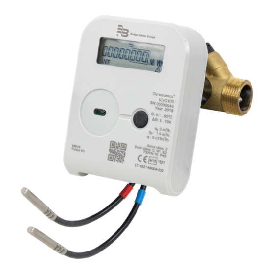
Application Field APPLICATION FIELD The Dynasonics® UHC100 ultrasonic heating and cooling energy meter (hereinafter referred to as “the meter”) is designed to measure the consumption of heating and cooling energy and record data in two separate registers It is used in individual or district heating facilities (for example, residential buildings, enterprises, organizations or supply facilities) for the commercial metering of consumed energy where water is the heat carrier This is a compact microprocessor meter for mounting optionally either at the supply or return heat exchange circulation... -
Page 8: Operating Principle
Operating Principle OPERATING PRINCIPLE The flow rate is measured on the basis of the ultrasonic measurement principle The ultrasonic signal is sent along the flow sensor upstream and downstream between the ultrasonic sensors, which alternately perform transmitter and receiver functions The flow rate is calculated on the basis of the measured propagation time difference (downstream and upstream) The temperature differential between the supply and return flows is measured by resistive temperature sensors The electronic unit calculates the amount of consumed heat energy by integrating over time the difference of the enthalpies of supply and return heat carrier and provides the data on the display... -
Page 9: Installation Procedure
Installation Procedure INSTALLATION PROCEDURE General Requirements Prior to installing the meter: • Check the complete set of the meter with that specified in the technical documentation; • Check for any visible mechanical defects; • Check the configuration of the meter and change it, if necessary The meters may only be installed by qualified specialists in accordance with the requirements of this document and the meter installation design DO NOT lay signal wires closer than 2 in (5 cm) from power cables or cables of other devices... - Page 10 Installation Procedure OTEE: 1) The symbol shows that the meter is in the transport mode 2) *The marked parameters are displayed only in the transport mode 3) **The marked parameters can also be changed in the normal operation mode LCD Image Parameter Possibility to change Heat capacity...
- Page 11 Installation Procedure OTEE: 1) The symbol shows that the meter is in the transport mode 2) *The marked parameters are displayed only in the transport mode 3) **The marked parameters can also be changed in the normal operation mode LCD Image Parameter Possibility to change Parameter of the 1...
- Page 12 Installation Procedure OTEE: 1) The symbol shows that the meter is in the transport mode 2) *The marked parameters are displayed only in the transport mode 3) **The marked parameters can also be changed in the normal operation mode LCD Image Parameter Possibility to change Subscriber number...
-
Page 13: Electrical Wiring
Installation Procedure Electrical Wiring If the meter is to be powered from an external 230V AC or 24V AC/DC source, the cable of the meter intended for the purpose and respectively marked is connected to the respective source (see "Transportation and Storage" on page If the meter is completed with wire interfaces or the Pulse Input/Output function, the cables intended for the purpose and "Transportation and Storage"... -
Page 14: Mounting The Flow Sensors
Installation Procedure IMPORTANT DO NOT attach the electronic unit directly on the wall because there is a risk that moisture may condense on the walls of the room or the temperature of the surface of the wall may drop below 131° F (5 °C). Mount the unit to provide for an air space of at least 2 in. (5 cm) between the unit and the wall surface. -
Page 15: Operating Procedure
Operating Procedure OPERATING PROCEDURE Control Button The representation of measured and information data on the display is selected by the control button located on the upper part of the electronic unit Control Button Representation of Data Data are displayed on a liquid crystal, 8-digit display with special symbols for the representation of parameters, units of measurement, and Operating Modes: When the flow is flowing in the right direction, it is represented by a right arrow ;... -
Page 16: Menu Structure
Operating Procedure Menu Structure The diagram of the review of readings of the electronic unit in the Operating Mode is shown in Figure 2 The main integral readings (1 2) or error (1 1) are shown if the button was not pressed for more than 60 seconds Figure 2: Reviewing readings in the operating mode. - Page 17 Operating Procedure Viewing the Readings in the Operating Mode (User Menu) OTEE: This is a complete list of represented parameters It can be shortened at a specific meter for the convenience of the user Parameter Value Notes Integral heating energy 00000 000 Integral cooling energy 00000 000...
- Page 18 Operating Procedure Parameter Value Notes 1 11 Check number 0000 1 12 Error code and error beginning When there is no error, it only shows date Er: 0000 0001 When there is critical error, the images changes every second: error code and error beginning date 2017 01 01 The error code values are explained in...
- Page 19 Operating Procedure Parameter Value Notes m³ Settlement day integral heat Changes every second 00000 000 carrier volume and date 2017 01 01 m³ Settlement day integral pulse Changes every second 00000 000 input 1 value and date 2017 01 01 m³...
- Page 20 Operating Procedure Parameter Value Notes 2 11 Previous month integral Tariff 2 Changes every second 00000 000 energy and date 2017 01 01 m³ 2 12 Previous month integral heat Changes every second 00000 000 carrier volume and date 2017 01 01 m³...
- Page 21 Operating Procedure Parameter Value Notes m³/h 2 17 Previous month maximum Changes every second 0 000 flow-rate value and date 2017 01 01 2 18 Previous month supply heat Changes every second 0 0 °C carrier maximum temperature value and date 2017 01 01 2 19 Previous month return heat...
- Page 22 Operating Procedure Parameter Value Notes 2 23 Previous month minimum Changes every second 0 0 °C recorded temperature differential and date 2017 01 01 2 24 Recorded data and dates of When installing the meter, the selection previous months, similarly to can be set to the indication of the 2 8 –...
- Page 23 Operating Procedure Parameter Value Notes 3 10 Reporting day of the month -- -- 31 3 11 Tariff 1 configuration Example of Tariff 1, when Possible setting: T1-T2 is < 10 0 °C: One of measured parameters, 1 or 2 pulse input (if it is configured as an L1 10 0 °C input), one of the temperatures, or...
- Page 24 Operating Procedure Parameter Value Notes 3 18 Wire interface M-Bus 2 speed When a second wire interface is also 2400E bPS included Bits per second “E” – parity Even 3 19 Heat carrier type heat carrier type H: ---- “----” – water 3 20 Heat carrier type Transmitted in M-Bus telegrams...
- Page 25 Operating Procedure The indication of irrelevant parameters can be turned off Also, parameters that are not relevant to the set meter configuration will not be indicated The indication of parameters can be turned on or off by means of the configuration programme HEAT3-SERVICE through the optical interface when installing the meter (if the meter is in the transport mode) or connecting the jumper SERVICE at any time Viewing Calculator Readings in Test Mode...
- Page 26 Operating Procedure Parameter Value Notes TEST To activate energy pulses Activated by pressing and holding the tESt on output (when volume pulse button output is active) TEST m³ To activate volume pulse Activated by pressing and holding the tESt on output (when energy pulse button output is active)
- Page 27 Operating Procedure Error Codes Errors are encoded by a 4-digit code Meter status Temperature sensor T2 status Temperature sensor T1 status Flow sensor status Er: 0001 Code Name Description Status of calculator 0 - normal operation 1 - battery service life has expired (or in the meter was not powered when meter is powering externally) 2 - temperature differential is higher than permissible limits 4 - temperature differential is lower than permissible limits...
-
Page 28: Test Mode Control
Operating Procedure B – corresponds to error codes 8 + 2 + 1 C – corresponds to error codes 8 + 4 D – corresponds to error codes 8 + 4 + 1 E – corresponds to error codes 8 + 4 + 2 F –... - Page 29 Operating Procedure Activating the Test Mode with the Control Button The Test Mode (TEST) can be activated by the button (or through the optical interface with the programme HEAT3-SERVICE) In this case, the water volume simulation feature is not available Therefore, the Test Mode does not interfere with the normal Operating Mode (measured energy and volume are summed up at the operation mode registers) The activation of the Test Mode requires the following: By pressing and holding the button, select the INF page on the display;...
-
Page 30: Verification
Verification VERIFICATION The metrological control of the parameters of the meter is performed according to LST EN1434-5 TRANSPORTATION AND STORAGE The packaged meters can be transported by any covered vehicles During transportation, the meters must be reliably secured in order to prevent shocks or risk of movement inside the vehicle Protect the meters against mechanical damage and shocks The rooms where the meters are kept must be free from aggressive, corrosive materials Transportation and storage conditions: •... - Page 31 Cable Connections Cable Destination Cable Marking*** Wire Destination Wire Color Line brown M-Bus 1 interface MBUS1 Line white Line brown M-Bus 2 interface MBUS2 Line white Mbus1 Line brown Mbus1 Line white M-Bus interfaces (two) * MBUS Mbus2 Line yellow Mbus2 Line green Pulses (+)
-
Page 32: Dimensions
Dimensions DIMENSIONS Coupling Ø 0.098 Thread Thread BSPP THREAD Part Number Description 69234-004 Meter Coupling, 1-1/2 × 1-1/2 × 2 84 in 0 77/0 85 2 78/2 84 G 2 in 1-1/2 11-1/2 NPT 69234-003 Meter Coupling, 1 × 1 × 2 63 in 0 46/0 54 2 60/2 64 G 1-1/4 in... -
Page 33: Dn15 Threaded Connection G 3/4 In , Length = 110 Mm Or 165 Mm
Dimensions DN15 Threaded Connection G 3/4 in., Length = 110 mm or 165 mm G 3/4 in. 0.5 in. (12 mm) 4.3 in. 6.5 in. 3.1 in. (110 mm) (165 mm) (80 mm) 4.6 in. (116 mm) 3.5 in. (90 mm) Figure 6: Flow sensor q = 0.6/1.0/1.5 m³/h, Length L=110 mm (L=165 mm);... -
Page 34: Dn20 Threaded Connection G 1 In , Length = 130 Mm
Dimensions DN20 Threaded Connection G 1 in., Length = 130 mm G 1 in. 0.6 in. (14 mm) 4.3 in. 3.3 in. (130 mm) (83 mm) 4.6 in. (116 mm) 3.5 in. (90 mm) Figure 7: Flow sensor q = 2.5/1.5 m³/h, Length L=130 mm; connection type: thread G1 in. DN20 Threaded Connection G 1 in., Length = 190 mm G 1 in. -
Page 35: Dn20 Flange Connection D20, Length = 190 Mm
Dimensions DN20 Flange Connection D20, Length = 190 mm 0.7 in. 5.1 in. (17 mm) 4.4 in. (190 mm) (112 mm) Ø 75 4.6 in. (116 mm) 4×Ø 14 R52.5 3.5 in. (90 mm) Figure 9: Flow sensor q = 0.6/1.0/1.5/2.5 m /h;... -
Page 36: Dn25 Flange Connection Dn25, Length = 260 Mm
Dimensions DN25 Flange Connection DN25, Length = 260 mm 0.7 in. 10.2 in. (17 mm) 5.2 in. (260 mm) (131 mm) Ø 14 5.3 in. (134 mm) Ø 85 R57.5 3.5 in. (90 mm) Figure 11: Flow sensor q = 3.5/6.0 m /h;... -
Page 37: Dn40 Threaded Connection G 2 In , Length = 300 Mm
Dimensions DN40 Threaded Connection G 2 in., Length = 300 mm 4.6 in. (118 mm) 0.8 in. (21 mm) 4.6 in. (116 mm) G 2 in. 3.5 in. (90 mm) 11.8 in. (300 mm) Figure 13: Flow sensor q = 10.0 m /h;... -
Page 38: Dn50 Flange Connection Dn50 In , Length = 270 Mm
Dimensions DN50 Flange Connection DN50 in., Length = 270 mm 6.3 in. 10.6 in. (159 mm) (270 mm) Ø 125 6.3 in. (159 mm) 4×Ø 18 0.7 in. (18 mm) Figure 15: Flow sensor q = 15 m /h; L=270 mm; connection type: flanges DN50 DN65 Flange Connection DN65 in., Length = 300 mm 7.3 in. -
Page 39: Dn100 Flange Connection Dn100 In , Length = 300 Mm
Dimensions DN100 Flange Connection DN100 in., Length = 300 mm 8.9 in. (225 mm) 8 × R 11.5 14.2 in. (360 mm) 8.9 in. (225 mm) 0.7 in. (19 mm) Ø 190 Figure 18: Flow sensor q = 60 m /h;... - Page 40 Dimensions Overall Dimensions of Temperature Sensors Figure 19: Overall dimensions of the DS type temperature sensor Figure 20: PL type temperature sensor Figure 21: Overall dimensions of the PL type temperature sensor protective pocket Nominal Pipe Diameter Pocket Length in. (mm) DN20 to DN100 4 (100) DN125 to DN150...
- Page 41 Dimensions Figure 24: The sealing diagram of calculator (at the back side of the box): It shall be sealed additionally only if the breakable partitions are damaged (1 – the supplier’s seal is attached after installation; 2 – verification seal stickers are attached) Manufacturer’s Warranty Seal Sticker Manufacturer’s Warranty Seal Sticker Figure 25: Flow sensor qp = 0.6/1.0/1.5/2.5 m³/h sealing...
- Page 42 Dimensions Temperature Sensor Mounting Seal Measuring Element Sensor Centerline Temperature Sensor Mounting Pipe Seal Figure 31: Sensor installed using a T-piece Figure 32: Sensor installed using a valve T-piece Page 42 HYB-UM-03193-EN-02 November 2020...
-
Page 43: Meter Ordering Matrix
Meter Ordering Matrix METER ORDERING MATRIX UHC100 Meter Type Purpose of the meter: Flow sensor installation place: Code Heating In supply pipe energy meter In return pipe Heating and cooling In supply pipe energy meter In return pipe (standard) Min value of temperature Code 250* 3 K (standard) - Page 44 Meter Ordering Matrix Meter Ordering Matrix (continued) UHC100 Code Code 1.2 m (standard) 2.5 m Extra communication interface: Code Not included Protection class / Nominal pressure: Code Protection class / Nominal pressure: Code IP65 / PN16 IP65 / PN25 IP67 / PN16 (standard) IP67 / PN25 IP68 / PN16 IP68 / PN25...
- Page 45 Meter Ordering Matrix UHC100 Mounting set for temperature sensors: Code Mounting set for temperature sensors: Code Not included Tee (for DS type sensors) Valve (for DS type sensors) Protective sockets (for PL type sensors) Code Code Not included Flanges with gaskets Threaded with gaskets Only gaskets For welding with gaskets...
-
Page 46: Technical Specifications
Technical Specifications TECHNICAL SPECIFICATIONS Energy Measurement Accuracy class: 2 according to LST EN1434-1:2016 ; Class 2 Measurement Canada Energy measurement units: kWh; MWh; GJ; Gcal Maximum value of thermal power: 5 28 MW Flow Measurement Ratio of the permanent flow rate to the lower limit of the flow-rate (selectable by the user): = 100, or q = 250 (only for sensors with q = 1 5 m³/h;... -
Page 47: Pulse Inputs (Additional)
Technical Specifications Temperature limits of heat conveying liquid: 32…194° F (0 1…90° C) Custom-made, wall-mounted electronic unit: 32…266° F (0 1…130° C) Length of the connecting cable between the flow sensor and electronic unit: 4 ft (1 2 m) Custom-made: 8 ft or 16 ft (2 5 m or 5 0 m) Maximum admissible working pressure (nominal pressure PN): 232 psi or 363 psi (16 bar or 25 bar) -
Page 48: Data Recording And Storage
Technical Specifications Data Recording and Storage In its memory, the meter accumulates an archive of hourly, daily, and monthly-measured parameters Archive data can be read only by remote data reading means (see "Representation of Data" on page 15) The monthly data archive parameters that are also shown on the display are specified in "Viewing the Readings in the Operating Mode (User Menu)"... -
Page 49: External Communication Interfaces
Technical Specifications External Communication Interfaces Optical interface (always included, irrespective of the order) Ordered interface (to be specified when ordering the meter; both options can be selected): • M-Bus interface • RF 868 MHz interface The interfaces are intended for data reading and meter parametering When the meter is configured for being powered only from the internal battery, the time of communication through the additional interfaces is automatically limited to save the battery—16 hours per month on an average Unused communication limit is summed up If the limit is used, the interface is locked and the summing-up of a new limit will start only after the change of the hour (80 times each hour) -
Page 50: Meter Power Supply
Technical Specifications Meter Power Supply One of the options, depending on the meter configuration: • One or two internal AA-size 3 6 V lithium (Li-SOCl2) batteries with a service life of at least 15+1 years, • Or an external 12…42V DC or 12…36V 50/60 Hz AC voltage; consumption current not more than 20 mA, •... -
Page 51: Marking And Sealing The Meter
Marking and Sealing the Meter MARKING AND SEALING THE METER Marking the Meter The following is indicated on the front panel of the electronic unit of the meter: The manufacturer’s trademark, type and the type number of the meter, EU–type examination certificate number, factory number, year of manufacture, temperature measurement range, temperature difference measurement range, accuracy, environmental class according to LST EN1434-1, electromagnetic and mechanical environment class, flow measurement range (q ), temperature range for the sensors,... -
Page 52: Return Of Goods For Repair
Control. Manage. Optimize. Dynasonics is a registered trademark of Badger Meter, Inc Other trademarks appearing in this document are the property of their respective entities Due to continuous research, product improvements and enhancements, Badger Meter reserves the right to change product or system specifications without notice, except to the extent an outstanding contractual obligation exists ©...
Need help?
Do you have a question about the Dynasonics UHC100 and is the answer not in the manual?
Questions and answers