Table of Contents
Advertisement
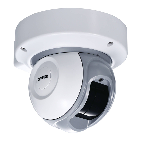
Laser Scan Detector
Laser Scan Detector
RLS-2020S
RLS-2020S
RLS-2020
RLS-2020
FEATURES
• 20 x 20 m (65 x 65 ft.), 95 degrees detection area
• Vertical and Horizontal detection area
• Multi-angle Adjustment Shell Structure (M.A.S.S.)
• Automatic area setting function
• Advanced area setting
• 4 adjustable detection areas on IP connection
• Total 3 outputs can be assigned for analog connection
• Anti-masking, Anti-rotation, Soiling, Device trouble, Tamper output (selectable)
• Paintable housing
• Supporting multiple network protocols
RLS-2020S
• Indoor and Outdoor use
• Indoor high resolution mode
• Indoor throw-in mode
• Area selection
• Environmental disqualification circuit (DQ)
CONTENTS
1-1 PREPARATION........................................................................................... 1
1-2 PRECAUTIONS .......................................................................................... 1
1-3 PARTS IDENTIFICATION........................................................................... 2
1-4 DETECTION AREA..................................................................................... 2
1-5 INSTALLATION WORK FLOWCHART....................................................... 2
2-1 MOUNTING TYPE ...................................................................................... 3
2-2 DISASSEMBLY ........................................................................................... 4
2-3 ASSEMBLY OPTIONS................................................................................ 4
3-1 REMOVING THE FRONT COVER ............................................................. 6
3-2 MOUNTING THE FRONT COVER ............................................................. 6
3-3 REMOVING THE LASER WINDOW ........................................................... 6
3-4 MOUNTING THE LASER WINDOW ........................................................... 6
3-5 WIRING CABLE ENTRY ............................................................................. 6
3-6 INSTALLING NETWORK CABLE ............................................................... 7
4-1 WALL OR CEILING MOUNTED.................................................................. 7
4-2 ANGLE ADJUSTMENT ............................................................................... 7
4-3 LASER AREA CONFIRMATION ................................................................. 7
5-1 WIRING ....................................................................................................... 8
5-2 PROGRAMMABLE SIGNAL OUTPUT........................................................ 8
5-3 PROGRAMMABLE SIGNAL INPUT (RLS-2020S only) .............................. 8
5-4 ETHERNET PORT (PoE)............................................................................ 8
5-5 MAINTENANCE SECTION ......................................................................... 8
5-6 MAINTENANCE PORT ............................................................................... 8
5-7 POWERING ON .......................................................................................... 8
5-8 INITIALIZATION TO FACTORY DEFAULT ................................................ 8
5-9 LED INDICATOR......................................................................................... 8
6-1 OVERVIEW ................................................................................................. 9
6-2 DETECTION CONFIGURATION ................................................................ 9
6-3 NETWORK CONFIGURATION................................................................. 10
6-4 NETWORK OPTIONS............................................................................... 10
6-5 AUTHENTICATION..................................................................................
6-6 MAINTENANCE ........................................................................................ 11
6-7 REDWALL EVENT CODE......................................................................... 11
7-1 DIMENSIONS............................................................................................ 11
8-1 SPECIFICATIONS .................................................................................... 11
8-2 OPTIONS .................................................................................................. 12
9-1 REPAINTING ............................................................................................ 12
1
INTRODUCTION
1-1
PREPARATION
• Read this instructions carefully prior to installation.
• This instructions uses the following warning indications to provide information
regarding correct usage of the product to prevent harm and damages to assets.
These warning indications are described below.
Ensure these precautions before reading the rest of this instructions.
(UL) 59-2408-4 1703-01
NO. 59-2408-6
INSTALLATION INSTRUCTIONS
mini
SECURITY
EN
U L
R
LISTED
Indoor/Outdoor model
Indoor only
.
Failure to follow the instructions provided with this indication and
Warning
improper handling may cause death or serious injury.
Failure to follow the instructions provided with this indication and
Caution
improper handling may cause injury and/or property damage.
This symbol indicates prohibition.
The specific prohibited action is provided in and/or around the figure.
This symbol requires an action or gives an instruction.
The check
mark indicates recommendation.
This product is not a safety component as per the machinery directive.
Do not use it for the purpose of machine safety.
Do not touch the unit base or power terminals of the product with a wet
hand (do not touch when the product is wet with rain, etc.). It may cause
electric shock.
Never attempt to disassemble or repair the product. It may cause fire or
damage to the devices.
Do not exceed the voltage or current rating specified for any of the
terminals, doing so may cause fire or damage to the devices.
Ensure the power is turned off before wiring.
Confirm the type of each terminal to ensure wiring is carried out correctly.
Whenever a commercial switching regulator is used, be sure to connect
PE (Protective Earth Terminal).
Hold the main unit securely when you install or service it. Exercise care
not to bump the product against nearby objects or drop it inadvertently.
This product is not capable of detecting objects in the dead zone of the
laser scan.
Do not use this product for an application where it is not capable of
covering the detection area required by the task.
Please note that the product can malfunction, including producing an
irregular output and committing a detection error, if it is exposed to
unfavorable environmental conditions such as strong ambient light,
electronic noises or mechanical vibrations.
Use of controls or adjustments or performance of procedures other than
those specified herein may result in hazardous radiation exposure.
Clean and check the product periodically for safe use.
If any problem is found, do not attempt to use the product as it is.
When disposing of this product, be sure to follow the waste-disposal
regulations of the country or region where it is used.
This product is intended to detect an intruder(s) and is not designed to
prevent theft, disasters or accidents. The manufacturer shall not be held
liable for any damage to user's property resulting from theft, disasters or
accidents.
1-2
PRECAUTIONS
Install the product only on a solid
surface.
Do not install the product on an
uneven surface.
10
Install the product so that the detection
area is not influenced by interference
from tall grass or tree branches waving
in the wind.
Do not use this product in environments where there may be oil mist particles
which may contaminate the window of the detector; thus causing detection errors
and possible corrosion which may lead to product failure.
There should not be any obstructs (e.g. lighting equipment, fire detectors,
cameras, poster, etc.) in the laser area.
After installation, any obstructs should not be carried/moved into the detection area.
EN-1
Warning
Caution
Avoid mounting near vents or devices
which cause high levels of smoke or
condensation.
Do not install or leave the product in a
location exposed to heat, vibrations or
impacts.
Do not use the product in an
environment where solvent fumes or
corrosive gases are present.
Advertisement
Table of Contents

Related Manuals for Optex Redscan Mini


Summary of Contents for Optex Redscan Mini
-
Page 1: Table Of Contents
(UL) 59-2408-4 1703-01 NO. 59-2408-6 INSTALLATION INSTRUCTIONS Failure to follow the instructions provided with this indication and Warning improper handling may cause death or serious injury. mini Laser Scan Detector Laser Scan Detector Failure to follow the instructions provided with this indication and Caution improper handling may cause injury and/or property damage. -
Page 2: Parts Identification
Cleaning the Product Accessories >> Clean the laser window using a damp cloth. A smeared laser window can limit the detection area due to the reduced laser sensitivity. In addition, heavy soiling of the Allen key: x1 Side cover cap: x3 window can induce detection errors. -
Page 3: Mounting Type And Assembly Options
MOUNTING TYPE AND ASSEMBLY OPTIONS -Type A • Vertical area for ceiling mount • Horizontal area for wall mount MOUNTING TYPE RLS-2020 has type A, B, C, and D to be installed. Select the correct type of assembly to match the installation. The detection area should cover the intruders approach. -
Page 4: Disassembly
DISASSEMBLY Note >> Note >> Disassembling is not required to use type A. (factory default) Before assembling, confirm the arrow mark on the wiring Disassemble the following parts in preparation. cover and the same with ABC on the main unit face Remove the side cover caps, side cover (L) and side covers (S). - Page 5 Assemble parts just as step 2 to 3 for type A. -Type B Note >> Rotate the main unit and insert the hook of the base cover into the position The positions of the fixing screw and side cover are shown below.
-
Page 6: Before Installation
BEFORE INSTALLATION WIRING CABLE ENTRY REMOVING THE FRONT COVER Loosen the screw on the front Rotate the front cover at opposite cover and pull the front cover side of the screw upward and forward with a snap. remove the hooks (x2). 1 knockout 2 wiring holes -Wiring hole on the back side... -
Page 7: Installing Network Cable
Insert the base hook in to the base cover and ensure that the fixing screw INSTALLING NETWORK CABLE does not jam against the cover. Close the base cover, and then tighten the 3 screws to fix it. Disassemble the cable gland. Seal Pass the Ethernet plug with the correct order and direction. -
Page 8: Parts Layout Inside And Their Functions
PoE (IEEE802.3 standard) After power on, all the indicators are turned on for approx. 60 seconds and then the status and alarm indicators are turned off. Cat5e or During this period, REDSCAN mini itself performs initial settings. above (320) m (ft) -
Page 9: Setting
• Save Config. Transfers and saves the setting configured on the browser. Press this button A web browser can be used to configure the Redscan mini settings. after configuring the setting. The ethernet port on the base unit and the maintenance port on the main unit can be used for configuration. -
Page 10: Network Configuration
[ New user ID ] Default : REDSCAN • Network Configuration of Main Ethernet Port [ New password ] Default : OPTEX Configuration Type: Default “STATIC” To reflect the setting, press [Save Config] button to send and save the setting to Select “STATIC”... -
Page 11: Maintenance
146 × 160 × 160 mm (5.8 × 6.3 × 6.3 inch) Dimensions (H× W× D) Weight 1.0 kg (2.2 Lbs) Note >> Contact to OPTEX to get more detailed specifications of REDWALL Event Code. * Specifications and design are subject to change without prior notice. EN-11... -
Page 12: Options
: Laser area checker REPAINTING RLS-PB : Pole mounting bracket RLS-RB : Recessed mount kit RLS-LW : REDSCAN mini laser window Remove the side cover cap, side cover L and side cover Ss. (refer to 2-2 1 ) UL Statement - UL approved indoor mode and outdoor mode only.
Need help?
Do you have a question about the Redscan Mini and is the answer not in the manual?
Questions and answers