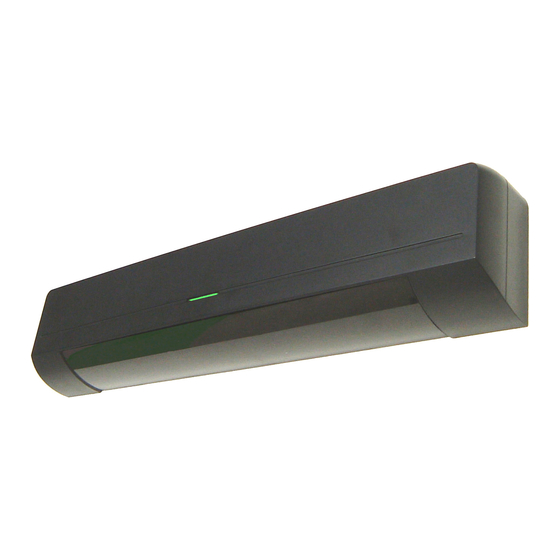
Table of Contents
Advertisement
Quick Links
ELITE ST
MANUFACTURER'S STATEMENT
This Installation manual will help identify and resolve some of the most common installation issues. This guide will also
verify that all Dipswitch settings and Area Depth adjustments are properly set. If after verifying all nine steps proper
operation has not been achieved, please contact our Technical Support Team at (800) 877-6656.
Placement the Sensor heads
1
Mounting templates should be aligned with the pivot edge of the door .
Template Labeled "Right Hinge Side".
NOTE
Edge of the template aligned the hinge of door.
Make sure to attach the both templates (Swing Side , Approach Side) on the same horizontal level.
Fix the Sensor heads
2
1. Drill mounting holes and a wiring hole according to the mounting template.
NOTE
Make a hole on one side. Door loop will be install on one side only.
2. Remove the mounting template.
3. Fix the OA-605 sensor heads.
Wiring
5
Wiring the cable as shown below.
Connect pass thru
For concealed wiring
the communication cable to
both OA-605 sensor heads.
Feed the connector.
OA-605
Communication cable
0.2m (8")
OA-605
For double door connection
OA-605
Communication cable
0.2m (8")
OA-605
Dipswitch settings of OMD-101
6
Set dipswitch as shown below.
OMD-101
Black arrow : See the setting below
ON
Gray arrow : N/A
1
2
3
4
Dipswitch1
If setting is ON, after 10 sec. of "Dead Lock" , OC-905C(S) emits Creep Signal.
NOTE
See ELITE ST specification manual for each dipswitch definitions.
Installation manual
Template Labeled "Left Hinge Side".
How to remove the cover
Insert the flat head screw driver and push it down.
Hold the top and remove the cover.
For surface wiring.
Fix the cover.
Knockout the cover.
Communication cable 2.2m (7'3")
OC-905C(S)
Door loop
Master: Encoder1
(Dipswitch4:OFF)
See section7.
Communication cable 2.2m (7'3")
OC-905C(S)
Door loop
Slave: Encoder2
(Dipswitch4:ON)
See section7.
Read this manual carefully before install. Failure to read this manual may cause improper operation and may result in
serious injury or death of a person.The meanings of the symbols are as follows.
Please study the following first and then read the contents of this manual.
WARNING
Disregard of warning may cause the improper operation causing death or serious injury of a person.
CAUTION
Disregard of caution may cause the improper operation causing injury of a person or damage to objects.
NOTE
Special attention is required to the section of this symbol.
Fix the door loop
3
1. Knockout the side of a cover closer to OA-605.
2. Connect the door loop cable to OA-605.
3. Fix the door loop cover.
OMD-101 on MC521 controller
4
The procedure for OMD-101 is same for that of SENTREX MICRO BOARD
WARNING
Turn "Power Switch" on MC521 controller OFF.
1. Remove one of hexagon standoffs from MC521controller.
2. Tight the longer hexagon standoff (ELITE_ST Accessories) .
3. Connect OMD-101 to Sentrex (J401) connector on MC521Controller.
4. Fix the board with the shorter hexagon standoff (ELITE_ST Accessories) .
Daughter board
OMD-101
Supplied flexible wire
shroud is cut to fit on
site.
Connect cable
Fix the cover.
Wiring cable 0.6m (2')
TB1
TB2
TB3
TB4
TB5
OC-905C(S)
Power Supply (+)
Communication TXD
Wiring cable 0.6m (2')
Communication RXD
Power Supply (-)
Dipswitch settings of OC-905C(S)
7
Set dipswitch as shown below.
OC-905C(S)
ON
1
2
3
Dipswitch3
ON : knowing act application, OFF : fully automatic application.
Dipswitch4
ON : "Slave (Encoder2) ", OFF : "Master(Encoder1) ".
When connected a single door (one door), set to OFF.
When connected a double door (two doors), select ON or OFF respectively.
TB1
TB2
TB3
TB4
TB5
OC-905C(S)
All activation devices must be connected to Purple wires.
For knowing act application, connect purple
wires to push plate (or to Activation sensor).
See section7.
NOTE
On pairs, purple wires from OC-905C(S)s connect
in parallel. Be sure to observe polarity(+ to +, - to -).
Do not connect purple wires to MC-521.
PUSH
PLATE
Activation
sensor
OMD-101
STANLEY
CONTROLLER
MC521
: Red
: Green
: White
: Black
Red arrow : Mandatory
Black arrow : See the setting below
Gray arrow : N/A
4
5
6
7
8
NOTE
See ELITE ST specification manual for each dipswitch definitions.
STANLEY
CONTROLLER
TB1 PIN1
TB1 PIN2
TB1 PIN3
TB1 PIN4
Advertisement
Table of Contents

Summary of Contents for Optex Pro Swing Elite ST
- Page 1 ELITE ST Installation manual Read this manual carefully before install. Failure to read this manual may cause improper operation and may result in serious injury or death of a person.The meanings of the symbols are as follows. Please study the following first and then read the contents of this manual. MANUFACTURER'S STATEMENT WARNING Disregard of warning may cause the improper operation causing death or serious injury of a person.
- Page 2 Dipswitch settings of OA-605 Setup process Verify proper dipswitch settings of OA-605 sensor heads (specifically dipswitches 7 & 8 of left bank and 1 There are 2 ways for a setup.Term Definitions ; thru 8 of right bank). First/Reset Auto Learn : The "Auto Learn"...


Need help?
Do you have a question about the Pro Swing Elite ST and is the answer not in the manual?
Questions and answers