Table of Contents
Advertisement
Quick Links
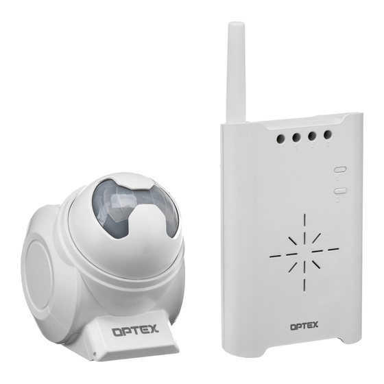
CHIME BOX W/RELAY RECEIVER
RC-20U INSTALLATION INSTRUCTIONS
Please read this manual carefully before installation.
1 CAUTION AND WARNING
WARNING
1. Harsh environments
Do not use the RC-20U outdoors, severe conditions as out of warranted
temperature, rapid temperature change, high humidity, or steam.
This may cause the unit to malfunction.
2. Tampering
Any changes or modifications not expressly approved by OPTEX could void the user's
authority to operate the equipment.
3. Adaptor
Do not use any other AC adaptor except what is included.
2 PARTS IDENTIFICATION
Zone indicator 1
Zone indicator 2
Zone indicator 3
Switch 1
Power
indicator
Power
Switch
Switch 2
Speaker
Adaptor
Jack
FRONT
Note: When you recycle this product, please disassemble product and recycle according to state law.
4 INSTALLATION
Wall Mounting
Use the mounting screw
on a wall. Leave some
length of the screw out
for mounting hole of the
RC-20U.
Terminal connection
Any device with a zero
voltage input terminal can
be connected to this
terminal. This may include
electronic locks,
emergency sounding
Remove the connection
devices, and automatic
terminal cover
reporting equipment.
6 TEACH TRANSMITTER CODES TO RC-20U "LEARN MODE"
Each transmitter has a unique transmitter code which can be automatically learned by RC-20U.
The RC-20U's zones must be taught to respond to the appropriate transmitter. (No transmitter is taught on default setting.)
Activate "LEARN MODE"
A) The RC-20U automatically
starts in "LEARN MODE"
if no transmitter code has
been programmed.
B) Press and hold switch 1
until the power indicator
starts to flash.
Note:
・ Verify that each transmitter has been successfully learned by RC-20U by triggering them.
・ Each zone can learn max. 3 transmitters.
・ Zone indicator shows the activated transmitter by the number of flash.
(e.g. If learned second transmitter in zone 1 is activated, zone 1 indicator flashes twice.)
・ Single transmitter cannot be learned by multiple zones
・ RC-20U learned code will keep memorized even if turning OFF the power.
2000
Mounting
hole
Connection
terminal
cover
Stand
Output
connection
terminal
(Inside of the
cover)
BACK
Desktop
Pull out the stand on the
back of the RC-20U and
place it on any flat surface.
Use the terminal marked
.
"COM-N.O." for N.O.
devices and "COM-N.C." for
N.C. devices.
Zone 1
OR
Receiver starts
in Zone 1.
FEATURES
・ Compatible with TD-20U (Indoor/Outdoor Sensor Transmitter),TS-10U (Hand-Held Transmitter),
TR-20U(Repeater), TC-10U(Door/Window Transmitter) and any transmission units of WIRELESS1000 series.
・ Identifies 4 zones by 3 different tones and LED lights (3 normal zones + 1 continuous zone).
・ Able to learn 12 transmission codes (Each zone can learn 3 transmitters maximum).
・ Automatic "Learning" function facilitates to preset transmission codes to RC-20U.
・ Over 8 million codes possible, eliminates interference from neighbors.
・ Latches into alarm with "Continuous mode" function.
・ Programmed "Utility Output Mode" to inactivate chime tone (applicable for zone 3).
・ Adjustable duration for terminal output.
・ Adjustable volume.
・ Low battery indicator to recognize transmission units' battery status.
・ Powered by a 9VDC adaptor(Included).
CAUTION
1. Impact/Shock
Impact or Shock can cause severe damage or break the RC-20U.
2. Electric Devices
Use RC-20U at least 3ft (1m) away from electronic devices such as TVs, Radios, PCs,
Microwave ovens, or any other devices with an electric motors.
This may cause the unit to malfunction.
3. Transmission range
Transmission range may decrease under the following conditions:
- Either transmission units or RC-20U installed on a metal surface.
- Presence of a steel door, reinforced concrete or other metal obstructions between
transmission units and RC-20U.
- Places near strong radio sources such as broadcast stations or substation.
4. Cleaning
Harsh cleaners such as paint removers or benzene may ruin the surface. Use a soft wet
cloth and mild soap to clean.
Function
Activating "LEARN MODE" and
Switch 1
"TERMINAL OUTPUT DURATION
MODE".
Activating "VOLUME ADJUSTMENT
Switch 2
MODE" and making selection.
AC Adaptor
Mounting screw
Remove knockouts
Close the connection
according to wiring
terminal cover.
needs.
Teach the transmitter code to RC-20U
Activate the transmitter you wish to teach the receiver.
(
The corresponding zone indicator flash rapidly at interval's of
1 sec according to the related transmitter.
Zone 2
Zone 3
Press switch 2 to advance to the next zone
and chime sound.
Erasing codes from RC-20U's memory.
1) Hold down switch 1 until the power indicator starts to flash.
2) Press switch 2 until the appropriate zone indicator is lit.
3) Press switch 1 to erase. The zone indicator will start to flash.
(Note: All programming in that particular zone will be erased.)
4) Press switch 2 a few times until the power indicator stops flashing and remains lit.
Erasing all codes from RC-20U. (Return to the factory default)
To erase all programming, turn on power while holding switch 1.
3 TRANSMISSION RANGE (REFERENCE)
Transmission range must be changed according to environment.
Please check if system works properly for the site.
In the case of insufficient transmission range, use TR-20U (Repeater unit)
to extend range.
Sensor unit
2000ft (Open field, line of sight)
TD-20U
150ft (Stucco/Plaster construction)
100ft (Concrete construction)
Repeater
TR-20U
Contact unit
TC-10U
1400ft (Open field, line of sight)
150ft (Stucco/Plaster construction)
100ft (Concrete construction)
Button unit
TS-10U
5 POWER CONNECTION
Use only the power adaptor supplied with the
product.
Zone 4
Operation Status
(Special/ refer 8 )
Press switch 2 to return to
normal operation status.
Receiver/ Repeater
RC-20U/ TR-20U
Normal
Light
Blink
Advertisement
Table of Contents

Related Manuals for Optex WIRELESS 2000


Summary of Contents for Optex WIRELESS 2000
-
Page 1: Wall Mounting
Use RC-20U at least 3ft (1m) away from electronic devices such as TVs, Radios, PCs, 2. Tampering Microwave ovens, or any other devices with an electric motors. Any changes or modifications not expressly approved by OPTEX could void the user’s This may cause the unit to malfunction. authority to operate the equipment. - Page 2 FCC ID : DC9RC-20U • It is determined that the product malfunction has resulted from improper use or from an The changes or modifications not expressly approved by the OPTEX could void the user’s authority to operate the equipment. To accident.
Need help?
Do you have a question about the WIRELESS 2000 and is the answer not in the manual?
Questions and answers