Rosslare AC-215 Installation Manual
Single and double door access control unit
Hide thumbs
Also See for AC-215:
- Hardware installation manual (44 pages) ,
- Hardware installation manual (42 pages)

Related Manuals for Rosslare AC-215


Summary of Contents for Rosslare AC-215
- Page 1 2012 October AC-215 Single and Double Door Access Control Unit Installation Manual...
- Page 2 ROSSLARE. ROSSLARE reserves the right to revise and change this document at any time, without being obliged to announce such revisions or changes beforehand or after the fact.
-
Page 3: Table Of Contents
1. Introduction to AC-215 ACU ..........9 Main Features ................... 11 1.1.1 AC-215 ..................... 11 1.1.2 System ...................... 11 1.1.3 AC-215 Single and Double Door Access ............. 11 Software ................... 12 2. Technical Specifications ..........13 Electrical Specifications ..............13 2.1.1 Main Unit ....................13 2.1.2 Outputs .................... - Page 4 AY-H12, AY-J12, AY-K12, AY-L12, AY-M12 Prox Readers ....30 AY-C19 / AY-D19 PIN & Prox Readers ..........31 AY-L23 RF Reader ................31 A. Connecting between MD-N32 and AC-215 ....32 Hardware Requirements..............32 Topics ....................32 Connections – PC Side ..............32 Connections –...
- Page 5 Table of Contents B. Connecting between MD-N33 and AC-215 ....36 Hardware Requirements..............36 Topics ....................36 Connections – PC Side ..............36 Connections – AC-215 Panel Side ............. 36 MD-N33 Configuration with AxTrax™ AS-525 ........37 PC modem – configuration and initialization ........37 Remote modem –...
- Page 6 List of Figures List of Figures Figure 1: AxTrax™ AS-525 and AC-215 System ..........10 Figure 2: Remote Site Modem Configuration ..........23 Figure 3: MD-N32 Configuration Connecting a Single Panel ......24 Figure 4: Connecting Multiple Access Control Panels with MD-N32 ....24 Figure 5: Wiring Four AC-215 Inputs ............
- Page 7 List of Tables List of Tables Table 1: DIP Switches and their Functions ............. 18 Table 2: Switch Baud Rates ................18 Table 3: Available Panel Addresses ............... 20 Table 4: RS-232 Connection ................. 22 AC-215 Installation Manual...
- Page 8 ROSSLARE ENTERPRISES LIMITED and/or its related companies and/or subsidiaries’ (hereafter:"ROSSLARE") exclusive warranty and liability is limited to the warranty and liability statement provided in an appendix at the end of this document.
-
Page 9: Introduction To Ac-215 Acu
Clients are able to modify the database; for example, define new employees and/or their access permissions. AxTrax™ AS-525 can run under Windows 98, 2000, NT or XP operating systems. Figure 1 is an example of how the AxTrax™ AS-525 and AC-215 system can be set up. AC-215 Installation Manual... -
Page 10: Figure 1: Axtrax™ As-525 And Ac-215 System
Introduction Figure 1: AxTrax™ AS-525 and AC-215 System AC-215 RS-485/232 AC-215 AC-215 AC-215 Single Door Converter Single Door Double Door Up to 32 ACUs AxTrax™ RS232 RS485 RS485 RS485 Software Door Maglock Monitor Exit button Reader 2 readers Reader, Keypad,... -
Page 11: Main Features
1.1.3 AC-215 Single and Double Door Access The operation mode is first defined on the 8-Way DIP switch on the AC-215 main PCB (the third switch defines the operation mode as described in Section 4.2) and then defined as either single or double door using the AxTrax™ AS- 525 software;... -
Page 12: Software
AxTrax™ AS-525 can be run on Windows 98, 2000, NT and XP. For UL installations, the installer must configure the system as fail-safe to comply with NFPA (National Fire Protection Association) regulations. AC-215 Installation Manual... -
Page 13: Technical Specifications
Operating Temperature: 0°C to 49°C (32°F to 120.2°F) Operating Humidity: 0 to 85% (non-condensing) 2.1.6 Mechanical Specifications Enclosure's Dimensions (LxWxD): 264 x 334 x 84.5 mm (10.4 x 13.2 x 3.4 in.) Weight: 3.77 kg (8.31 lbs) AC-215 Installation Manual... -
Page 14: Inputs And Outputs
Inputs and Outputs Inputs and Outputs This chapter discusses the AC-215 ACU input and output requirements. Inputs 3.1.1 Release to Exit Button (REX) REX enables quick exit from a premises. The following should be defined: Single door controller: Door 1 – IN1 Double door controller: Door 1 –... -
Page 15: Tamper
Grant Access Automatic Relock 3.1.7 Door Alarm This output is activated when either an alarm occurs in the system, or automatically by a time zone. The following should be defined: AC-215 Installation Manual... -
Page 16: Auxiliary
The reader’s tamper connects to the ACU and can generate an alarm. The reader’s green LED input is activated by the ACU when in the Card and PIN secure mode to inform the user to enter his personal PIN number after entering his card. AC-215 Installation Manual... -
Page 17: Keypad
Door 1 Keypad – Reader 1 IN/OUT Door 2 Keypad – Reader 2 IN/OUT The keypad type must be a Rosslare format keypad. A keypad has to be connected for any reader mode that requires PIN code entries, such as Card or PIN, PIN only or Card and PIN (Secured mode). -
Page 18: Dip Switch Settings Configuration
The following lists switch 1 and 2 status and baud rate: Table 2: Switch Baud Rates Switch 2 Baud Rate Switch 1 Switch 2 Baud Rate 9600 38400 19200 57600 The ACU baud rate must be identical to the host PC’s serial port baud rate. AC-215 Installation Manual... -
Page 19: Acu Type
Door 1 alarm output Door 2 lock strike Door 2 alarm output Inputs Release to exit door1 Door 1 monitor input Release to exit door 2 Door 2 monitor input AC-215 Installation Manual... -
Page 20: Acu Addressing
The ACU address is defined in the AxTrax™ AS-525 software. For successful communications, the dipswitch must be defined with the same address. Table 3 displays the 32 address settings available: Table 3: Available Panel Addresses Address Switch 4 Switch 5 Switch 6 Switch 7 Switch 8 AC-215 Installation Manual... - Page 21 DIP Switch Settings Configuration Address Switch 4 Switch 5 Switch 6 Switch 7 Switch 8 AC-215 Installation Manual...
-
Page 22: Communications
Up to 32 ACUs can be linked together and connected to a single communication port on the PC. The RS485 interface must be used when multiple controllers are connected. The serial port used to control the ACU is assigned in the AxTrax™ AS-525 software Network Properties dialog box. AC-215 Installation Manual... -
Page 23: Daisy Chain
The modem is used when the distance between the ACU and the PC is greater than the recommended serial connection distance or in an application where an alternative RS232/RS485 network is unavailable. Figure 2 illustrates remote site modem configuration with AC-215. Figure 2: Remote Site Modem Configuration For more information, see Appendix B. -
Page 24: Communication Through The Local Area Network (Lan)
The following type of connection is used when a LAN network already exists and therefore the long RS485 network is not required. This schematic illustrates the connection of a single AC-215 to the PC using the LAN network. MD-N32 must be first configured by Rosslare's Netconfig software. The setting is stored in a non-volatile memory in the MD-N32. -
Page 25: Wiring
Wiring Wiring Inputs Figure 5 illustrates wiring for four AC-215 inputs. For further details, see Chapter 3. Figure 5: Wiring Four AC-215 Inputs Outputs Figure 6 and Figure 7 illustrate wiring for two main types of 12VDC electric release mechanisms. Other electrical devices can be switched using the voltage free relay contacts. -
Page 26: Power Supply
Figure 7: Door Lock – Fail Open 6.2.1 Power Supply Figure 8 illustrates wiring between the PS-14 power supply and the AC-215. It is recommended to add a 12 VDC lead acid backup battery to backup power if the main fails. -
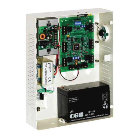
Page 27: Ac-215 Access Control Panel Diagram
Wiring Figure 8: AC-215 Wiring to Power Supply AC-215 Access Control Panel Diagram Figure 9 presents a complete view of the AC-215 control panel’s PCB, including all connector buttons and LED schematics (not to scale). Figure 9: AC-215 Wiring Communications... -
Page 28: Reader
When extending cable distance be careful with the color of the cable cover. The distance is limited by the Wiegand standard. Figure 10: Reader Cable Coloring Key: Black Green White G.LED Brown Tamper Purple AC-215 Installation Manual... -
Page 29: Accessories (Proximity Readers)
Slim stylish design (Mullion) Includes LED indicator Audible buzzer indicator Built in tamper (w/ Rosslare controllers) Includes bell button (w/ Rosslare controllers) AY-C11 / AY-D11 Prox Readers with Bell Reading distance: 8 to 10cm ... -
Page 30: Ay-C11 / Ay-D11 Prox Readers
For indoor use Slim stylish design (USA gang box) Bi-color light indicator Audible buzzer indicator (w/ Rosslare controllers) Built in tamper (w/ Rosslare controllers) AY-H12, AY-J12, AY-K12, AY-L12, AY-M12 Prox Readers Reading distance: 7 to 12cm ... -
Page 31: Ay-C19 / Ay-D19 Pin & Prox Readers
For indoor use Slim stylish design (USA gang box) Bi-color light indicator Audible buzzer indicator Built in tamper (w/ Rosslare controllers) Includes bell button (w/ Rosslare controllers) AY-L23 RF Reader Read range: 70 meters (200 feet) ... -
Page 32: Connecting Between Md-N32 And Ac-215
Connect the AC-215's RS-485 outlet to MD-14 4 wires cable. Make sure that J1 (on the AC-215) is set to RS485 Mode. If the jumper was not set properly, make the change, turn the power of AC-215 off, wait few seconds and turn it on. - Page 33 Connecting between MD-N32 and AC-215 The network type should be selected as TCP/IP. Click the configuration tab and wait until "searching" is complete. Click OK. Select the suitable MAC address from the MD-N32 list. The MD-N32's MAC address should be labeled on the MD-N32's box.
- Page 34 Connecting between MD-N32 and AC-215 Click Apply to send the configuration to the unit and wait for following message: Click OK to start verification process and wait for the following message: 10. Click OK twice and verify that the configuration was accepted by the AxTrax™...
- Page 35 Connecting between MD-N32 and AC-215 The MD-N32 and AxTrax™ AS-525 software are now configured ready for testing. From this stage, you can continue working per the procedure for adding a new panel to the AxTrax™ AS-525. AC-215 Installation Manual...
-
Page 36: Connecting Between Md-N33 And Ac-215
Connect MD-N33's DB9 female jack to MD-14's DB9 female jack. Connect the AC-215's RS-485 outlet to the MD-14 4-wire cable. Make sure that J1 (on the AC-215) is set to RS-485 Mode. If the jumper was not set properly, make the change, turn the power of AC-215 off, wait few seconds and turn it on. -
Page 37: Md-N33 Configuration With Axtrax™ As-525
Connecting between MD-N33 and AC-215 MD-N33 Configuration with AxTrax™ AS-525 Add a new network using the AxTrax™ AS-525 software (for more details see the AxTrax™ user manuals). The network type should be selected as Modem. PC modem – configuration and initialization... - Page 38 Connecting between MD-N33 and AC-215 Change the "number of dial attempts" as needed. In the Additional dialing string options field, for most applications, the default dialing string of AS-525 is enough. The dialing string is displayed in the window. Adding or editing dialing string is allowed by clearing the "Use default"...
-
Page 39: Remote Modem - Configuration And Initialization
Connecting between MD-N33 and AC-215 Remote modem – configuration and initialization Click the Remote modem tab to configure the remote modem. In the Settings section: For most applications, the default initialization string of AS-525 is enough. The initialization string is displayed in the window. -
Page 40: Remote Modem Status
Connecting between MD-N33 and AC-215 The MD-N33 and AxTrax™ AS-525 software are now configured ready for testing. From this stage, you can continue working per the AxTrax™ AS-525 adding new panel procedure. Remote Modem Status When a panel is connected to a modem network, you can see the status of the modem by clicking the phone icon in the toolbar. -
Page 41: Restoring Factory Default Configuration
Restoring factory default configuration If you forgot the existing password, there is an option to return AC-215 to factory default (with password: AxTrax) Returning to factory default changes also all the doors and readers configuration to factory default and clears all the users' properties. -
Page 42: Power Supply Specifications
Power Supply Indication Tamper Output (open collector) Indicates faulty power Power LEDs Power In (AC) – Green LED1 Main power Power Out (DC) – Red LED2 Low voltage Charger (BAT) – Red LED3 Backup battery low voltage AC-215 Installation Manual... -
Page 43: Limited Warranty
EMEDY OVERAGE In the event of a breach of warranty, ROSSLARE will credit Customer with the price of the Product paid by Customer, provided that the warranty claim is delivered to ROSSLARE by the Customer during the warranty period in accordance with the terms of this warranty. - Page 44 XCLUSIONS AND IMITATIONS ROSSLARE shall not be responsible or liable for any damage or loss resulting from the operation or performance of any Product or any systems in which a Product is incorporated. This warranty shall not extend to any ancillary...
- Page 45 Rosslare Security Products, Inc. support.cn@rosslaresecurity.com Southlake, TX, USA Toll Free: +1-866-632-1101 India Local: +1-817-305-0006 Fax: +1-817-305-0069 Rosslare Electronics India Pvt Ltd. support.na@rosslaresecurity.com Tel/Fax: +91 20 40147830 Mobile: +91 9975768824 Europe sales.in@rosslaresecurity.com Rosslare Israel Ltd. Rosh HaAyin, Israel Tel: +972 3 938-6838 Fax: +972 3 938-6830 support.eu@rosslaresecurity.com...
Need help?
Do you have a question about the AC-215 and is the answer not in the manual?
Questions and answers