Rosslare AC-215 Hardware Installation Manual
Single-door and double-door access control unit
Hide thumbs
Also See for AC-215:
- Installation manual (45 pages) ,
- Hardware installation manual (44 pages)

Subscribe to Our Youtube Channel
Related Manuals for Rosslare AC-215


Summary of Contents for Rosslare AC-215
- Page 1 AC-215 Single-Door and Double-Door Access Control Unit Hardware Installation Manual Models: AC-215 AC-215U...
- Page 2 ROSSLARE. ROSSLARE reserves the right to revise and change this document at any time, without being obliged to announce such revisions or changes beforehand or after the fact.
-
Page 3: Table Of Contents
ACU Baud Rate ................. 17 ACU Type ..................18 4.2.1 Single Door Controller ................18 4.2.2 Double Door Controller ................18 ACU Addressing ................19 5. Communications ............. 21 Serial Connection ................21 5.1.1 RS-232 Connection ................... 21 AC-215 Installation Manual... - Page 4 6.3.1 Power Supply .................... 28 AC-215 Access Control Panel Diagram ..........29 Reader ....................30 A. Connecting between MD-N32 and AC-215 ....31 Hardware Requirements..............31 Topics ....................31 Connections – PC Side ..............31 Connections – AC-215 Panel Side ............. 31 MD-N32 Configuration with AxTraxNG ..........
- Page 5 Figure 7: Door Lock – Fail Closed ..............26 Figure 8: Door Lock – Fail Open ..............27 Figure 9: AC-215 Wiring to Power Supply ............. 28 Figure 10: AC-215 Wiring Communications ..........29 Figure 11: Reader Cable Coloring ..............30...
- Page 6 List of Tables List of Tables Table 1: Description of AC-215 Panels ............8 Table 2: DIP Switches and their Functions ............. 17 Table 3: Switch Baud Rates ................17 Table 4: Available Panel Addresses ............... 19 Table 5: RS-232 Connection ................. 21...
- Page 7 ROSSLARE exclusive warranty and liability is limited to the warranty and liability statement provided in an appendix at the end of this document. ...
-
Page 8: Introduction
AxTraxNG can run under Windows 98, 2000, NT or XP operating systems. The AxTraxNG software and associated computer monitoring equipment has not been evaluated by UL. Figure 1 is an example of how the AxTraxNG and AC-215 system can be set AC-215 Installation Manual... -
Page 9: Figure 1: Axtraxng™ And Ac-215 System
Introduction Figure 1: AxTraxNG™ and AC-215 System AC-215 RS-485/232 AC-215 AC-215 AC-215 Single Door Converter Single Door Double Door AxTraxNG RS-232 RS-485 RS-485 RS-485 Up to 32 ACUs Software Door Maglock Monitor Exit Button Reader 2 readers Reader, Keypad, Reader In... -
Page 10: Control Panel Components
Introduction Control Panel Components The AC-215 control panel consists of the following components: AC-215 controller board Enclosure PS-14 power supply Software The AxTraxNG software is user-friendly and intuitive. Its graphic interface is used to define settings, which are downloaded to the ACU and event logs which are uploaded to the PC to generate reports. -
Page 11: Technical Specifications
Output: 16 VAC 2.5 A (40 VA) supplied, internal to unit AC-215U Input: 120 VAC Output: 16.5 VAC 2.42 A (40 VA) Class 2 (not included). Use wall plug-in unit such as Universal Power Group Part No. UB1640W. AC-215 Installation Manual... -
Page 12: Power Supply Specifications
Power Supply Indication Tamper Output (open collector) Indicates faulty power Power LEDs Power In (AC) – Green LED1 Main power Power Out (DC) – Red LED2 Low voltage Charger (BAT) – Red LED3 Backup battery low voltage AC-215 Installation Manual... -
Page 13: Inputs And Outputs
Inputs and Outputs Inputs and Outputs This chapter discusses the AC-215 ACU input and output requirements. Inputs 3.1.1 Release to Exit Button (REX) REX enables quick exit from a premises. The following should be defined: Single door controller Door 1 – IN1 Double door controller Door 1 –... -
Page 14: Tamper
Door 1 – OUT1 Door 2 – OUT2 The output can sink current from any power supply (see Section 2.2). In a time zone door locking is activated in the following modes: Grant Access Automatic Relock AC-215 Installation Manual... -
Page 15: Door Alarm
Follow input – output follows the input state Toggle – active for every change in the output trigger – the trigger changes state Time – active for a specified time and closes when the timer ends AC-215 Installation Manual... -
Page 16: Card Readers
Door 1 – Keypad – Reader 1 IN/OUT Door 2 – Keypad – Reader 2 IN/OUT The keypad type must be a Rosslare format keypad. A keypad has to be connected for any reader mode that requires PIN code entries, such as Card or PIN, PIN only or Card and PIN (Secured mode). -
Page 17: Dip Switch Settings Configuration
The following lists switch 1 and 2 status and baud rate: Table 3: Switch Baud Rates Switch 1 Switch 2 Baud Rate 9600 19200 38400 57600 The ACU baud rate must be identical to the host PC’s serial port baud rate. AC-215 Installation Manual... -
Page 18: Acu Type
Door 1 lock strike Door 1 alarm output Door 2 lock strike Door 2 alarm output Inputs REX Door1 Door 1 monitor input REX Door 2 Door 2 monitor input AC-215 Installation Manual... -
Page 19: Acu Addressing
The ACU address is defined in the AxTraxNG software. For successful communications, the dipswitch must be defined with the same address. Table 4 displays the 32 address settings available: Table 4: Available Panel Addresses Address Switch 4 Switch 5 Switch 6 Switch 7 Switch 8 AC-215 Installation Manual... - Page 20 DIP Switch Settings Configuration Address Switch 4 Switch 5 Switch 6 Switch 7 Switch 8 AC-215 Installation Manual...
-
Page 21: Communications
Up to 32 ACUs can be linked together and connected to a single communication port on the PC. The RS-485 interface must be used when multiple controllers are connected. The serial port used to control the ACU is assigned in the AxTraxNG software Network Properties dialog box. AC-215 Installation Manual... -
Page 22: Daisy Chain
The modem is used when the distance between the ACU and the PC is greater than the recommended serial connection distance or in an application where an alternative RS-232/RS-485 network is unavailable. Figure 2 illustrates remote site modem configuration with AC-215. Figure 2: Remote Site Modem Configuration For more information, see Appendix B. -
Page 23: Communication Through The Local Area Network (Lan)
The following type of connection is used when a LAN network already exists and therefore the long RS-485 network is not required. This schematic illustrates the connection of a single AC-215 to the PC using the LAN network. MD-N32 must be first configured by Rosslare's Netconfig software. The setting is stored in a non-volatile memory in the MD-N32. -
Page 24: Wiring
Wiring Wiring General Wiring Diagram Figure 5 illustrates the general wiring layout of the AC-215. Figure 5: Wiring For UL installations, the following signal lines are not allowed to be run outside of the protected area: • 12 VDC 1.5 A + and (-) •... -
Page 25: Inputs
Wiring Inputs Figure 6 illustrates wiring for four AC-215 inputs. For further details, see Chapter 3. Figure 6: Wiring Four AC-215 Inputs Outputs Figure 7 and Figure 8 illustrate wiring for two main types of 12 VDC electric release mechanisms. Other electrical devices can be switched using the voltage free relay contacts. -
Page 26: Figure 7: Door Lock - Fail Closed
Wiring Figure 7: Door Lock – Fail Closed AC-215 Installation Manual... -
Page 27: Figure 8: Door Lock - Fail Open
Wiring Figure 8: Door Lock – Fail Open AC-215 Installation Manual... -
Page 28: Power Supply
Wiring 6.3.1 Power Supply Figure 9 illustrates wiring between the PS-14 power supply and the AC-215. It is recommended to add a 12 VDC lead acid backup battery to backup power if the main fails. If the main output is 12 VDC, wire it to the (PS-14); otherwise support your power supply according to output requirements. -
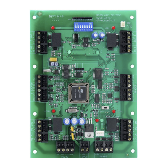
Page 29: Ac-215 Access Control Panel Diagram
Wiring AC-215 Access Control Panel Diagram Figure 10 presents a complete view of the AC-215 control panel’s PCB, including all connector buttons and LED schematics (not to scale). Figure 10: AC-215 Wiring Communications AC-215 Installation Manual... -
Page 30: Reader
When extending cable distance be careful with the color of the cable cover. The distance is limited by the Wiegand standard. Figure 11: Reader Cable Coloring Key: Black Green White G.LED Brown Tamper Purple AC-215 Installation Manual... -
Page 31: Connecting Between Md-N32 And Ac-215
Connect the AC-215's RS-485 outlet to MD-14 4 wires cable. Make sure that J1 (on the AC-215) is set to RS-485 Mode. If the jumper was not set properly, make the change, turn the power of AC-215 off, wait few seconds and turn it on. -
Page 32: Md-N32 Configuration With Axtraxng
Connecting between MD-N32 and AC-215 MD-N32 Configuration with AxTraxNG To configure the MD-N32: Add a new network using the AxTraxNG software (for more details, see the AxTrax user manuals.) The network type should be selected as TCP/IP. Configuration Click the tab and wait until "searching"... - Page 33 Connecting between MD-N32 and AC-215 In the Configuration area, type the IP Address and Subnet that the network administrator supplied you. In the Port field, enter 1000. In the Speed area, select the speed of your serial connection (9600/19200/ 38400/57600).
- Page 34 Connecting between MD-N32 and AC-215 10. Click OK twice and verify that the configuration was accepted by the AxTraxNG software. The MD-N32 and AxTraxNG software are now configured ready for testing. From this stage, you can continue working per the procedure for adding a new panel to the AxTraxNG.
-
Page 35: Connecting Between Md-N33 And Ac-215
Make sure that the power LED (Red) is on. Connect the MD-N33's DB11 jack to telephone wall mount using the telephone cable. Connect MD-N33's DB9 female jack to MD-14's DB9 female jack. Connect the AC-215's RS-485 outlet to the MD-14 4-wire cable. AC-215 Installation Manual... -
Page 36: Md-N33 Configuration With Axtraxng
Connecting between MD-N33 and AC-215 Make sure that J1 (on the AC-215) is set to RS-485 Mode. If the jumper was not set properly, make the change, turn the power of AC-215 off, wait few seconds and turn it on. -
Page 37: Pc Modem - Configuration And Initialization
Connecting between MD-N33 and AC-215 PC Modem – Configuration and Initialization Configuration Modem configuration Click the tab to get the screen. In the Dialing section: In the "Remote modem phone number" field, enter the destination telephone number to call. Change the "number of dial attempts" as needed. -
Page 38: Remote Modem - Configuration And Initialization
Connecting between MD-N33 and AC-215 If a failure message appeared, check the modem connections and repeat the last steps. Remote Modem – Configuration and Initialization To configure a remote modem: Click the Remote modem tab to configure the remote modem. -
Page 39: Remote Modem Status
Connecting between MD-N33 and AC-215 Set the number of rings before the PC modems will answer. Connect the remote modem to the PC via the selected com port and click Apply to initialize the PC modem. Click OK for the successful initialization. -
Page 40: Restoring Factory Default Configuration
Restoring Factory Default Configuration If you forgot the existing password, there is an option to return AC-215 to factory default (with password: AxTrax) Returning to factory default changes also all the doors and readers configuration to factory default and clears all the users' properties. -
Page 41: Limited Warranty
The full ROSSLARE Limited Warranty Statement is available in the Quick Links section on the ROSSLARE website at www.rosslaresecurity.com. Rosslare considers any use of this product as agreement to the Warranty Terms even if you do not review them. AC-215 Installation Manual... - Page 42 Fax: +86 755 8610 6101 Southlake, TX, USA support.cn@rosslaresecurity.com Toll Free: +1-866-632-1101 Local: +1-817-305-0006 India Fax: +1-817-305-0069 support.na@rosslaresecurity.com Rosslare Electronics India Pvt Ltd. Tel/Fax: +91 20 40147830 Europe Mobile: +91 9975768824 sales.in@rosslaresecurity.com Rosslare Israel Ltd. Rosh HaAyin, Israel Tel: +972 3 938-6838 Fax: +972 3 938-6830 support.eu@rosslaresecurity.com...
Need help?
Do you have a question about the AC-215 and is the answer not in the manual?
Questions and answers