Table of Contents
Advertisement
Quick Links
Advertisement
Table of Contents

Related Manuals for Dräger HFG 000 Series


Summary of Contents for Dräger HFG 000 Series
- Page 1 Technical manual X-am® 3500/8000 HFG 000* / HFG 001*...
- Page 2 This page has been left blank intentionally. Technical manual X-am® 3500/8000...
- Page 4 %LEL Vol% 20.9 08:43 08:43 Warning Switching off... Battery low! Battery empty 12:02 11:07 12:02 11:07 12:02 11:07 12:02...
-
Page 5: Table Of Contents
Contents Contents Safety-related information ..............Information on safety notes and warnings ........1.1.1 Safety notes..............1.1.2 Warnings ................Basic safety information..............Use in areas subject to explosion hazards ........Conventions in this document ............... Meaning of the warning notes............Trade marks..................Typographical conventions ............. - Page 6 Contents 4.7.4 Blocking alarm ..............4.7.5 Deleting (application) peaks ..........Calling the Quick Menu..............Opening information ............... 4.10 Measuring ..................4.10.1 Special features when measuring with the pump ..... 4.10.2 Carrying out measuring with the pump......4.11 Measurements with wizards ............4.12 Carrying out confined space entry measurements with the wizard 4.13...
- Page 7 Contents 6.10 Labelling field/label for strap ............6.11 Mounting the clip................6.12 Radio-Frequency Identification (RFID) ........... 6.13 Cleaning..................Configuration ................... Standard gas configuration............. Configuring the gas detector............7.2.1 Configuring the gas detector with the Dräger X-dock and reading the data memory 7.2.2 Configuring the gas detector with the PC and reading the data memory...
-
Page 8: Safety-Related Information
Safety-related information Safety-related information Information on safety notes and warnings Safety notes and warnings warn of dangers and provide instructions for the safe use of the product. Failure to observe these safety notes and warnings may result in personal injury or damage to property. 1.1.1 Safety notes This document contains sections with safety notes which warn of dangers. - Page 9 Safety-related information Oxygen deficient atmospheres Measurements in oxygen deficient atmospheres (<12 vol. % O ) may return incorrect displays on the CatEx sensor. In this case the CatEx sensor cannot provide a reliable measurement. ► Remove the device from the area. The CatEx sensor in oxygen deficient or oxygen enriched environments Incorrect measured values may be displayed in an oxygen deficient or oxygen enriched environment.
-
Page 10: Conventions In This Document
Conventions in this document Conventions in this document Meaning of the warning notes The following alert icons are used in this document to provide and highlight areas of the associated text that require a greater awareness by the user. A definition of the meaning of each icon is as follows: Alert icon Signal word... -
Page 11: Abbreviations
Conventions in this document Term Description Monitoring Monitoring without pump (diffusion) Monitoring with pump (with pump adapter) Capture range The capture range refers to a measured value range within which minor variations in measured values (such as signal noise, variations in concentration) do not cause variations in the display. - Page 12 Conventions in this document Abbreviation Explanation STEV Short time exposure value, average value of exposure over a short period of time (generally 15 minutes). Time weighted average, average shift values are generally lim- ited to eight hours exposure per day per workplace for 5 days a week during a work lifetime.
-
Page 13: Description
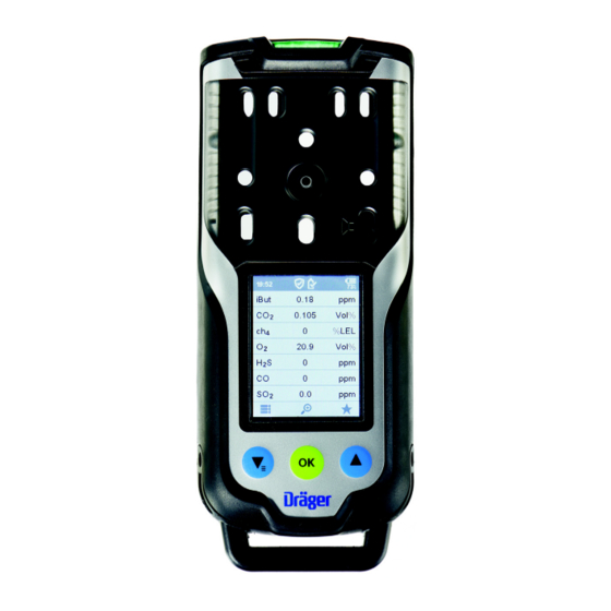
Description Description Product overview The graphics are displayed on the fold-out page. Graphic A Display Charge LED green/red Locking screw for an additional Labelling field (X-am 8000 only) charging module Power supply unit Induction charger Graphic B Gas inlets Horn Thread port for pumps and calibra- Pump outlet and inlet tion adapter... -
Page 14: Intended Use
Description Intended use Dräger X-am 3500/8000 is a portable gas detector for clearance measurements and for the continuous monitoring of the concentration of several gases in ambient air in the workplace and in explosion-hazard areas. The X-am 3500 allows measuring up to 4 gases in accordance with the DrägerSensors (XXS O , XXS H S LC, XXS CO LC, XXS NO... -
Page 15: Sensor Slot Positions X-Am 8000
Description Sensor slot positions X-am 8000 Sensor slot Configuration HPP 1 PID or IR sensor HPP 2 IR or CatEx sensor EC 1-3 EC sensors Further device options for X-am 8000 The following device options are available if needed: – Pump –... -
Page 16: Operation
Operation Operation Operating concept Navigation is done with the 3 multifeature buttons and the dynamic navigation bar (see Graphic E on the fold-out page). The navigation bar changes dynamically depending on the available interactions. Symbol explanations 4.2.1 feature buttons Symbol Explanation Confirm action/dialog / return to menu Confirm all... -
Page 17: Device Status
Operation 4.2.4 Device status Symbol Explanation Overview of the bump test intervals activated (additional infor- mation for the D-Light feature). There are no gas alarms or errors. Monitoring of the calibration intervals activated, D-Light function deactivated (additional information for the D-Light function). There are no gas alarms or errors. -
Page 18: Signalling Concept
Operation Symbol Explanation Readings below the measurement range Channel error Blocking alarm ##### Value too high to be displayed Signalling concept 4.3.1 Acoustic operation signal A periodic acoustic signal indicates that the device is functional. The acoustic operation signal can be deactivated. For further information, see the following chapter: "Activating silent mode", page 33 4.3.2 Visual operation signal... -
Page 19: Switching On The Gas Detector
Operation 4.4.2 Switching on the gas detector 1. Hold down the OK button for approx. 3 s. The display shows a countdown. The switch-on sequence and the warm-up phase of the sensors start. The following display appear one after the other: –... -
Page 20: Logging A User In Or Out
Operation 2. Select and confirm Switch off. The gas detector may only be switched off without a prior sign-on if the Switch- off allowed feature is activated using the Dräger CC-Vision PC software. Factory setting: activated When the gas detector is placed in the charging cradle, it switches off automatically. -
Page 21: Preparations For Operation
Operation To log in a user: 1. Select in measuring mode and confirm the dialog. 2. Select and confirm Login. 3. Enter the four-digit user level password and confirm each digit. To sign out a user: 1. Select in measuring mode and confirm the dialog. 2. -
Page 22: Monitoring Measuring Mode
Operation WARNING Incorrect measured values! Only for diffusion mode: If water seals the gas inlets on the gas detector (e.g. in heavy rain or if the gas detector is submerged in water), incorrect measured values may be returned. ► With the display facing downward, shake the gas detector to remove the water. CAUTION High readings outside of the LEL display range or a blocking alarm may indicate an explosive concentration. -
Page 23: Alarms
Operation 4.7.1.3 Activating the pump To activate the pump in (normal) measuring mode: 1. Place, align and tighten the pump adapter on the thread port on the top cover. Check that the pump adapter is mounted correctly. Avoid bending the pump adapter. -
Page 24: Deleting (Application) Peaks
Operation If the measuring range is exceeded significantly at the CatEx channel (very high concentration of flammable materials), a blocking alarm is triggered. This CatEx blocking alarm can be acknowledge by switching the gas detector off and then on again in fresh air. X-am 8000 only: This does not apply in the case of an activated over range for methane. -
Page 25: Measuring
Operation Option Description Gas statistics The following gas statistics are avail- able: – Select Shift peak to display the exposure peaks for all gasses. – Select Application peak to display the application peaks for all gasses. – Select TWA values to display the available TWA values for all gasses. -
Page 26: Carrying Out Measuring With The Pump
Operation The wizards are only available for X-am 8000. For the DrägerSensors XXS CI2, COCI2, O3 as well as amine and odorants, there are no wizards for confined spaces and leak searching, as these materials can not be pumped (properly) through tubes. In addition to the materials listed above, there may also be other materials for which there are no flushing times available in the gas detector. - Page 27 Operation 2. Mount the pump adapter to the gas detector. Make sure that both guide pins are in the correct grooves. Check that the pump adapter is mounted correctly. If the pump adapter is mounted correctly, the leak test starts automatically. If the leak test does not start, the gas detector is not ready for use.
-
Page 28: Measurements With Wizards
Operation 2. Remove the pump adapter. ✓ The pump is flushed and the gas detector automatically switches to diffusion mode. 4.11 Measurements with wizards The gas detector has wizards for easily preparing the measurements and for measurement displays optimised for the measurement. There are wizards for the following applications: –... -
Page 29: Carrying Out Leak Searches With The Wizard
Operation The displayed flushing time shows the minimum wait time required for the measurement gas to reach the sensor from the sampling location in an ideal scenario. This applies to the use of a Dräger sampling hose (fluoroelastomer, brand new, dry, clean) with an internal diameter of 3 mm. Other fixtures (e.g. pre-tube) extend the minimum wait time and must also be taken into consideration. -
Page 30: Carrying Out A Benzene/Pre-Tube Measurement With The Wizard
Operation To carry out a leak search: 1. Sign in with the required user level. 2. Select > Leak Search in measuring mode. 3. Confirm the successful leak test to start the measurement. The device emits tones in the “Individual measuring channel” display which increase in frequency as the gas concentration increases. - Page 31 Operation 1. Mount the pump adapter to the gas detector. Make sure that both guide pins are in the correct grooves. 2. Connect the dust and water filter (3) to the short hose piece (4) on the pump adapter (5). 3.
-
Page 32: Making Measurement
Operation Use an adapter piece for varying hose diameters if necessary (minimum internal diameter: 3 mm). 4.14.2 Making measurement Use a new pre-tube for each individual measurement with a pre-tube. Requirements: – The gas detector is switched on. – The user is signed in with the corresponding user level. –... -
Page 33: Configuring The Device Settings
Operation 4.15 Configuring the device settings Briefly press simultaneously to navigate to Monitoring. To open the device settings: 1. Select in measuring mode and confirm the dialog. 2. Sign in with the required user level, if necessary. 3. Select and confirm Settings. 4.15.1 Activating day or night mode 1. -
Page 34: Activating Or Deactivating Bluetooth ® (X-Am 8000 Only)
Operation ® 4.15.6 Activating or deactivating Bluetooth (X-am 8000 only) 1. Open the device settings. 2. Select Bluetooth. ® 3. Activate or deactivate Bluetooth 4.16 Activating an automatic over range An automatic over range can only be activated for the sensors DrägerSensor CatEx 125 PR (order number 68 12 950) and CatEx 125 PR Gas (order number 68 13 080) with the measurement gas methane. - Page 35 Operation Previously set alarm thresholds are maintained in order to ensure that in the presence of hydrogen (H ) the alarm of the IR Ex Channel is triggered earlier if required. Technical manual X-am® 3500/8000...
-
Page 36: Troubleshooting
Troubleshooting Troubleshooting If the following remedial measures are unsuccessful, contact DrägerService. Error Error Cause Remedy Life time expired Life time of the gas detec- Reconfigure the life time tor expired with the Dräger CC-Vision PC software. Device locked Gas detector locked by X- Unlock the gas detector dock with X-dock or the X-dock... -
Page 37: Warnings
Troubleshooting Error Cause Remedy Oxygen deficiency Insufficient oxygen for the Operate the gas detector correct functionality of the in atmospheric conditions. CatEx sensor Value negative Measured value in nega- Carry out a fresh air cali- tive range bration / zero-point calibra- tion Sensor missing Sensor faulty or not con-... - Page 38 Troubleshooting Warnings Cause Remedy Calibration expires soon Calibration interval expires Carry out a span calibra- soon tion Calibration expired Calibration interval of the Carry out a span calibra- (compensation)channel tion expired Logger almost full Data logger memory 90 % Read out the data memory full (with the GasVision PC software) and/or delete it.
-
Page 39: Maintenance
Maintenance Maintenance WARNING Risk of explosion! To reduce the risk of ignition of a flammable or explosive atmosphere, observe the following: ► Do not open the gas detector in explosion-hazard areas. WARNING Danger to health! Test gas may damage health if inhaled. ►... -
Page 40: Perform Bump Test
Maintenance Perform bump test The bump test can be performed as follows: – Bump test with the wizard (quick bump test) – Bump test with X-dock (quick or extended bump test) Dräger recommends using the extended bump test for cross calibrations (Dräger X-dock instructions for use). - Page 41 Maintenance To perform a bump test: 1. Mount the calibration adapter to the gas detector. Make sure that both guide pins are in the correct grooves. 2. Connect the hose to the test gas cylinder and the inlet on the calibration adapter. 3.
-
Page 42: Calibrate The Gas Detector
Maintenance 9. Remove the calibration adapter. If there was an error during the bump test: 1. An error is displayed for the measuring channel. 2. Repeat the bump test. 3. If necessary, replace the sensor. Calibrate the gas detector WARNING Incorrect measured values! An incorrect calibration may prevent alarms from triggering, or alarms may trigger late. -
Page 43: Carrying Out A Single-Gas Calibration
Maintenance Requirements: – Fresh air calibration can only be carried out if at least one sensor supports the fresh air calibration. – The fresh air must be free of measurement or interfering gasses. – The gas detector is switched on and warm-up phases 1 and 2 are complete. To carry out a fresh air calibration: 1. - Page 44 Maintenance X-am 8000 only: When implementing an active over range with the CatEx sensor (measurement gas: methane), observe chapter 4.16. Use a standard test gas. Allowed test gas concentration: DUAL IR Ex 1)2) 1)2) 20 to 100 %LEL / 5 to 100 vol % IR Ex DUAL IR CO 0.05 to 5 Vol%...
-
Page 45: Carrying Out A Multi-Gas Calibration
Maintenance 12.If necessary, press to overrule the stability control. In this case, a calibration happens immediately. The new measured value is displayed for confirmation. The result is displayed as follows: single-gas calibration successful. single-gas calibration failed. 13.The single-gas calibration is complete when measuring channel successfully passed or failed the single-gas calibration. - Page 46 Maintenance 2. Mount the calibration adapter to the gas detector. Make sure that both guide pins are in the correct grooves. 3. Connect the test gas cylinder to the calibration adapter. 4. If needed, connect a second hose (max. length: 2 m) to the second outlet on the calibration adapter to direct the test gas to an exhaust or outside.
-
Page 47: Carrying Out A Cross Calibration
Maintenance If there was an error during the multi-gas calibration: – Repeat the multi-gas calibration or carry out a single-gas calibration. – Inspect the sealing contours and surfaces on the calibration adapter as well as the front cradle of the housing to make sure they are free of damage. –... -
Page 48: Exchanging, Adding Or Removing A Sensor
Maintenance If the specified temperature range (5 to 35 °C) is not reached or is exceeded, charging stops automatically. This extends the charging time. After a return to the temperature range, charging continues automatically. The gas detector can be switched on again in the charging cradle and is then supplied with electrical current during operation. - Page 49 Maintenance To add a physical sensor, follow the same procedure used to exchanging a sensor. However, instead of the a sensor, there is a sensor placeholder in sensor damper. When the sensor type is exchanges, the sensor damper must also be exchanged accordingly.
- Page 50 Maintenance 6. Rotate the gas detector and carefully lift it out of the upper cradle. 7. Exchanging the EC sensors: a. Remove the sensor sealing plate from the EC sensors. b. Place the special tool on the trough. Using the accompanying special tool (1), carefully lift out the desired EC sensor (2).
- Page 51 Maintenance WARNING X-am 8000: Risk of incorrect measured values! In pump mode and after calibration, incorrect measured values may be returned if the following sensors are used on the sensor positions EC2 and EC3. ► The DrägerSensors XXS O3, XXS Cl2 and XXS COCl2 may only be used in sensor position EC1.
-
Page 52: Cleaning The Pid Lamp (X-Am 8000 Only)
Maintenance Next steps: ► After every sensor exchange, the fresh air calibration / zero-point calibration must first be carried out followed by the span calibration (multi-gas or single- gas). ► For the XXS O , Dräger recommends testing the alarm feature with a suitable test gas after the fresh air calibration. -
Page 53: Exchange The Device Components
Maintenance 5. Use the tweezers to remove the UV lamp. Hook the tweezers under the UV lamp and carefully angle it toward the edge of the housing to lift it out of the opening (IV). 6. Hold the UV lamp by its cylindrical shaft and place the lamp window (C) flat on the surface of the polishing paper. - Page 54 Maintenance NOTICE Damage to components! The gas detector contains components at risk of charging. ► Before opening the gas detector to exchange the sensor, make sure that the operator is earthed in order to prevent damage to the gas detector. For example, earthing may be ensured by an ESD workplace (electro static discharge).
-
Page 55: Blind Bracket / Strap Retainer / Labelling Field/Label For Strap
Maintenance 6.9.2 Blind bracket / strap retainer / labelling field/label for strap 1. Remove both screws (1). 2. Pull out the bracket (2) and attach the new bracket or strap retainer. 3. Insert and tighten the screws (10 - 15 Ncm). 4. -
Page 56: Rfid Transponder
Maintenance 6.9.4 RFID transponder Requirements: – The gas detector is open. 1. Loosen 3 screws (Torx T8) on the options board. 2. Rotate the gas detector and carefully lift it out of the front housing cradle. 3. Remove the options board cover. 4. -
Page 57: Sensor Sealing Plate
Maintenance 3. Remove the vibration motor (1) from the mount in the upper cradle. 4. Insert the new vibration motor in the upper cradle. Make sure that it is aligned correctly. The imbalance faces down, and the contacts face the options board. 5. -
Page 58: Sensor Holders
Maintenance 6.9.8 Sensor holders Requirements: – The gas detector is open. 1. Loosen 3 screws (Torx T8) on the options board. 2. Rotate the gas detector and carefully lift it out of the front housing cradle. 3. Remove the sensor sealing plate from the EC sensors. For further information, see the following chapter: "Sensor sealing plate", page 57. - Page 59 Maintenance 4. Remove the 3 clips from the options board cover and remove the options board. 5. Carefully remove the flexstrip with the differential pressure sensor (1) from the pump block. 6. Carefully remove the power connection plug (2) from the options board. 7.
-
Page 60: Horn / Resonator
Maintenance 9. Insert the new pump into the existing pump block and mount the entire assembly. 10.Re-assemble the gas detector. Make sure that the connector cable of the pump is running in the correct direction. The connecting cables must be routed within the space between the pump and the pump block. -
Page 61: Labelling Field/Label For Strap
Maintenance 6.10 Labelling field/label for strap The label indicates things such as the installed sensors and other customer-specific information on the gas detector. The label can be applied to the labelling field provided or on the strap buckle. The labels used by Dräger (e.g. standard label, colour: silver, order number: 83 27 645) fulfil explosion protection requirements. -
Page 62: Cleaning
Maintenance unique hexadecimal ID number which can be read by a radio reading device. The markings are passive (do not have a battery). A current source is required for signal transmission. Intended use Devices can be found and administrated using RFID. A radio reading device is required to read the markings (see the list of accessories). -
Page 63: Configuration
Configuration Configuration Standard gas configuration Different settings can be selected to meet customer requirements on delivery. The current setting can be checked and changed with the Dräger CC-Vision PC software. The Dräger CC-Vision PC software can be downloaded at www.draeger.com/software. DrägerSensor Measuring Alarm A1... - Page 64 Configuration DrägerSensor Measuring Alarm A1 Alarm A2 range threshold - latch- threshold - - latching ackno acknow wledg ledge- eable able XXS NO [ppm] 0 ... 200 XXS NO [ppm] 0 ... 50 XXS NO LC [ppm] 0 ... 50 XXS SO [ppm] 0 ...
-
Page 65: Configuring The Gas Detector
Configuration PID HC PID LC ppb Substance CAS no. A1 [ppm] A2 [ppm] A1 [ppm] A2 [ppm] Methyl tert-butyl 1634-04- MTBE 0.87 1.06 ether (MTBE) n-Nonane 111-84-2 Nona 1.55 n-octane 111-65-9 Octa 1.93 2.14 Alpha-pinene 2437-95- aPin 0.38 0.48 Styrene 100-42-5 Styr 0.44 0.82... -
Page 66: Configuring The Gas Detector With The Pc And Reading The Data Memory
Configuration 7.2.2 Configuring the gas detector with the PC and reading the data memory 7.2.2.1 Connect the gas detector to a PC. Equipment: – DIRA USB cable (order number 83 17 409) – DIRA dongle mount (order number 83 25 859) Procedure: 1. -
Page 67: Device Settings
Device settings Device settings Only trained and qualified personnel may change the device settings. Factory settings Different settings can be selected to meet customer requirements on order. The setting can be checked and changed with the X-dock maintenance station or the Dräger CC-Vision PC software. -
Page 68: Device And Sensor Settings
Device settings Device and sensor settings Name: Area / setting Device settings: Password(s) Numerical range (4-digit) Acoustic operation signal Yes / No Switch-off mode “Switch off allowed” or “Switch off forbidden” or “Switch off forbidden in A2” 0 - 60 (in minutes; setting for exposure 1)2) Short-term exposure limit (STEL) alarm) -
Page 69: Alarm Settings
Device settings Alarm settings Acknowl- Alarms Display Latching LEDs Horn Vibration edgeable A1 ↑ (increasing) A2 ↑ (increasing) A1 ↓ (decreasing) A2 ↓ (decreasing) 2)3) STEL STEL Errors Battery pre-alarm Battery main alarm Device error Channel error 1) Acknowledgement only possible after the concentration has dropped below the alarm threshold. 2) The STEL alarm can be triggered with a delay of max. -
Page 70: Transport
Transport Transport The gas detector contains a lithium-ion battery. During transport, in particular air transport, of the gas detector, adhere to the relevant safety regulations and markings for lithium batteries. Technical manual X-am® 3500/8000... -
Page 71: Storage
Storage Storage Dräger recommends storing the gas detector in the charging cradle. The sensors are supplied with power even when the gas detector is switched off to ensure a faster warm-up time when switching on. When storing the gas detector outside of the charging cradle, power supply to the sensors is cut off automatically after 21 days. -
Page 72: Disposal
Disposal Disposal This product must not be disposed of as household waste. This is indicated by the adjacent symbol. You can return this product to Dräger free of charge. For information please contact the national marketing organizations or Dräger. Batteries must not be disposed of as household waste. This is indicated by the adjacent symbol. -
Page 73: Technical Data
Technical data Technical data 12.1 Gas detector Ambient conditions: during operation and storage -20 to +50 °C 700 to 1300 hPa 10 to 90 % (briefly up to 95 %) rel. hum. Degree of protection IP 67 Alarm volume Typically 100 dB (A) at a distance of 30 cm Orientation Battery... - Page 74 This page has been left blank intentionally. Technical manual X-am® 3500/8000...
- Page 75 www.norrscope.com This page has been left blank intentionally. Technical manual X-am® 3500/8000...
Need help?
Do you have a question about the HFG 000 Series and is the answer not in the manual?
Questions and answers