Dräger X-am 5600 Technical Handbook
Approved as type mqg 01, multi-gas monitor
Hide thumbs
Also See for X-am 5600:
- User manual ,
- Instruction manual (396 pages) ,
- Instructions for use manual (348 pages)
Table of Contents
Advertisement
Advertisement
Table of Contents

Related Manuals for Dräger X-am 5600


Summary of Contents for Dräger X-am 5600
- Page 1 ® Dräger X-am 5600 approved as type MQG 01** Multi-Gas Monitor Technical Handbook...
-
Page 2: Table Of Contents
Content Content For Your Safety ............4 Intended Use . - Page 3 Content Maintenance ............38 Maintenance intervals .
-
Page 4: For Your Safety
Portable gas detection instrument for the continuous monitoring of the concentration of several gases in the ambient air within the working area and in explosion-hazard areas. X-am 5600, depending on the instrument type and configuration of DrägerSensors: independent measurement of one up to six gases. -
Page 5: Tests And Approvals
Do not stick anything on the name plate on the gas detector. The technical suitability tests are valid for the X-am 5600 gas detector and the calibration cradle. The explosion-protection approvals are only valid for the X-am 5600 gas detector;... -
Page 6: Safety Instructions
Safety instructions WARNING To reduce the danger of explosion, do not mix new batteries with old batteries and do not mix batteries made by different manufacturers. WARNING Always disconnect the instrument from the power pack before carrying out any maintenance operations. WARNING Substitution of components may impair intrinsic safety. -
Page 7: What Is What
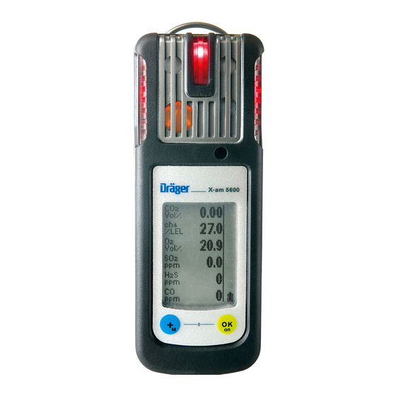
What is What Front panel Gas entry Alarm LED Buzzer X-am 5600 Display Rear panel IR interface Fastening clip Type plate Charging contacts Power pack Serial no. Display for 1 to 4 measuring channels: Measured gas Vol% display %LEL Measured gas... -
Page 8: Special Symbols
Special symbols Fault message, refer to page 15 Warning message, refer to page 15 The peak value display for all measuring gases, refer to page 15 The exposure evaluation display (TWA) for measuring gases, e.g., H S and CO, refer to page 15 The exposure evaluation display (STEL) for measuring gases, e.g., H S and CO, refer to page 15... -
Page 9: Configuration
Configuration Standard gas configuration DrägerSensor Measuring Alarm A1 Alarm A2 range DUAL IR Ex/CO DUAL IR-Ex [%LEL] 0 to 100 DUAL IR-CO [vol. %] 0 to 5 IR-Ex [%LEL] 0 to 100 IR-CO [vol. %] 0 to 5 XXS O [vol. -
Page 10: Standard Instrument Configuration
Different settings can be selected to meet customer requirements on delivery. The current setting can be checked and changed with the Dräger CC Vision software. A version of Dräger CC Vision which can be used for Dräger X-am 5600 is supplied with the instrument on CD. 2) In the case of O A1 is the lower alarm threshold: an alarm is triggered if the value is too low. - Page 11 By activating the H added signal, the LEL gas concentration of the activated DrägerSensor XXS H HC (6812025) is added to the LEL gas concentration of the activated DrägerSensor DUAL IR Ex/CO (6811960) or of the activated DrägerSensor IR Ex (6812180) and shown on the display at the position of the IR Ex display. NOTICE Previously set alarm thresholds are preserved so that in the presence of hydrogen (H2) the alarm of the IR Ex channel could be triggered earlier.
-
Page 12: Operation
Operation Before using the instrument for the first time, insert a charged NiMH T4 power pack or batteries approved by Dräger, see "Changing the batteries" on page 58. The instrument is now ready for operation. WARNING: To reduce the risk of ignition of a flammable or explosive atmosphere, strictly adhere to the following warning statements: Only use power pack types ABT 01xx, HBT 00xx or HBT 01xx. -
Page 13: Switching Off The Instrument
Switching off the instrument Press and hold the key and key at the same time until the countdown » 3 . 2 . 1 « shown in the display has elapsed. — Before the instrument is switched off, the visual, audible and vibration alarms are activated for a short time. -
Page 14: During Operation
LED WARNING When using an IR Sensor in the Dräger X-am 5600, the zero point and sensitivity must be adjusted after an impact load that causes a display other than zero for the IR sensor when the instrument is at fresh air. -
Page 15: Calling The Info Mode
Calling the Info Mode In measuring mode, press the key for approx. 3 seconds. If any warning or fault messages exist, the corresponding information or error codes are displayed (page 28 to page 35). Press the key successively for the next display. The peak values and the exposition values TWA and STEL are displayed. -
Page 16: Calling The Quick Menu
Calling the Quick Menu — Only the fresh air calibration/zero-point calibration is activated in the quick menu on delivery. The PC software Dräger CC Vision can be used to activate the bump test for the quick menu and/or the function for displaying and deleting peak values. ... -
Page 17: Quick Menu "Delete Peak Values
Quick menu "Delete peak values" Vol% After the function has been selected, the current peak values are displayed; the %LEL peak values special symbol appears in Vol% the display at the same time. The peak values can be deleted by pressing the key for 5 sec. -
Page 18: Calling The Calibration Menu
Calling the Calibration Menu — The calibration menu can only be accessed by entering a password. Password on delivery: » 001 « — The default password on delivery can be changed using the PC software Dräger CCVision. In measuring mode, press the key for at least 4 seconds. -
Page 19: Identifying Alarms
Identifying Alarms An alarm is displayed visually, audibly and through vibration in a specific pattern. NOTICE At low temperatures the legibility of the display can be improved by switching on the backlight. Concentration pre-alarm A1 The alarm is indicated by an intermittent alarm message: Display »... -
Page 20: Stel / Twa Exposure Alarm
STEL / TWA exposure alarm The alarm is indicated by an intermittent alarm message: Display » A2 « and » « (TWA) or » « (STEL) and measured value alternating: WARNING Risk to health! Leave the area immediately. After this alarm, the deployment of personnel is subject to the relevant national regulations. -
Page 21: Operation With Pump
Operation with pump Observe the following when performing measurements using the pump Perform visual inspection of the probe, if necessary. Wait for the flushing time to end. Flush the Dräger sampling hose or Dräger probes prior to each measurement with the air sample to be measured. - Page 22 Performing a measurement with the Dräger X-am Pump Required accessories (see "Accessories" on page 67): Dräger X-am Pump Sampling hose and probes Pump symbols: Pump battery 100 % charged Warning for pump (Gas detector can no longer detect pump.) Remaining charge of pump Leak test:...
- Page 23 WARNING Impairment of accuracy! After measuring high concentrations of nonane (>20 %LEL), the accuracy for measuring nonane is impaired. The pump is not suitable for long-term measurement of high concentrations of nonane. Performing a measurement with a manual pump adapter and rubber ball pump Required accessories (see "Accessories"...
-
Page 24: Configuring The Instrument
Configuring the Instrument To individually configure a instrument with standard configuration, the instrument must be connected with a PC. Dräger USB 2.0 CC-Vision USB DIRA with USB cable (order no. 83 17 409) Dräger USB 2.0 CC-Vision Calibration cradle (order no. 83 18 752) with inserted USB DIRA with USB cable (order no. - Page 25 Device settings NOTICE Only trained personnel are permitted to make changes to the device configuration. The following changes can be made to the device parameters for a device: Designation Field Password Numeric field (3-figure) Operating signal LED Yes/No Operating signal horn Yes/No Switch-off mode “Switch off permitted”...
- Page 26 Delay until error after expiry of cal. interval 0 - 10 (days) Activate user service life Yes/No User service life (days) 0 - 999 (if activated) Running in Yes/No LEL category “---” or “PTB” or “IEC” or “NIOSH” (if this is changed, the LEL factor will be altered to match) ToxicTwins (HCN) Yes/No...
-
Page 27: Read Database And Display Graphically
Read Database and Display Graphically To read the database of the instrument and display it graphically, the instrument must be connected with a PC. Dräger USB 2.0 GasVision USB DIRA with USB cable (order no. 83 17 409) Dräger USB 2.0 GasVision Calibration cradle (order no. -
Page 28: Faults, Cause And Remedy
Faults, Cause and Remedy Fault Cause Remedy Not possible to switch on Discharge the power pack Charge the power pack, the instrument page 59. Discharge the alkaline Insert new alkaline batteries, batteries page 58. Not possible to switch off The instrument is not set to Select measuring mode. - Page 29 Special symbol Cause Remedy » « and displayed numerical code: DrägerSensor XXS EC1 in Wait until warm-up time is the warm-up phase complete. DrägerSensor XXS EC1 in Wait until warm-up time is the warm-up phase complete. EC1 concentration has Carry out fresh air calibration/ drifted into the negative zero-point calibration, page 48.
- Page 30 Special symbol Cause Remedy » « and displayed numerical code: EC3 concentration has drifted Carry out fresh air calibration/ into the negative range zero-point calibration, page 48. The temperature is too high Operate the instrument within the allowed temperature range. The temperature is too low Operate the instrument within the allowed temperature range.
- Page 31 Special symbol Cause Remedy » « and displayed numerical code: IR CO concentration has Carry out zero-point calibration, drifted into the negative page 48. range The temperature is too high Operate the instrument within the allowed temperature range. The temperature is too low Operate the instrument within the allowed temperature range.
-
Page 32: Fault Messages
Fault messages Special symbol Cause Remedy » « and displayed numerical code: The customers service Reset the service life counter lifecounter has elapsed using Dräger CC Vision. The instrument is defective The instrument must be repaired by Service. Check sum error program The instrument must be code repaired by Service. - Page 33 Special symbol Cause Remedy » « and displayed numerical code: Battery pre-alarm of X-am Charge pump. Pump Battery alarm of X-am Pump Charge pump. The zero-point calibration/ Carry out fresh air calibration/ adjustment of DrägerSensor zero-point calibration, page 48. XXS EC1 is not valid The span calibration/ Carry out span calibration, adjustment of DrägerSensor...
- Page 34 Special symbol Cause Remedy » « and displayed numerical code: Error during the function test Repeat function test. Calibrate with gas (bump test) of or replace DrägerSensor XXS DrägerSensor XXS EC2 EC2, if necessary page 62. Failed filter test. Repeat filter test with X-dock. Failed rise time test.
- Page 35 Special symbol Cause Remedy » « and displayed numerical code: Error during warm-up Disconnect and reconnect acceleration DrägerSensor power pack or replace the XXS EC3 sensor. Sensor must not be loaded with gas within the first 5 minutes. The zero-point calibration/ Carry out fresh air calibration/ adjustment of DrägerSensor zero-point calibration, page 48.
- Page 36 Special symbol Cause Remedy » « and displayed numerical code: The measured value of Carry out zero-point calibration, Dräger Sensors IR CO is in page 48. the negative range Dräger Sensor IR CO is not Check Dräger Sensor IR CO inserted page 62.
- Page 37 Special symbol Cause Remedy » « and displayed numerical code: Failed filter test. Repeat filter test with X-dock. Failed rise time test. Repeat rise time test with X- dock. User parameters not feasible Check configuration of user parameters and adjust Error in Dräger Sensor IR Ex Check Dräger Sensor IR Ex, page 62.
-
Page 38: Maintenance
Maintenance Maintenance intervals The instrument should be inspected and maintained by suitably qualified persons annually. Comparisons: EN 60079-29-2 – Gas detectors - Selection, installation, use and maintenance of detectors for flammable gases and oxygen EN 45544-4 – Electrical apparatus used for the direct detection and direct concentration measurement of toxic gases and vapours - Part 4: Guide for selection, installation, use and maintenance ... -
Page 39: Added Signal
Sensor XXS H HC is operated in conjunction with a Dräger Sensor DUAL IR Ex/CO or a Dräger Sensor IR Ex sensor in the Dräger X-am 5600. Both units must be set to LEL. An added signal can be activated and deactivated via the Dräger CC-Vision PC software. - Page 40 ToxicTwins When the ToxicTwins feature is activated, the measuring channels of the XXS CO sensor and the XXS HCN sensor are offset against each other in such a manner that the device issues an alarm before the respective A1 alarm threshold is reached if both gases are detected at the same time.
-
Page 41: Carry Out Manual Bump Test
Carry out manual bump test WARNING In the case of a manual function test the effect of the H added signal must be taken into account accordingly. NOTICE A potentially activated H added signal is automatically temporarily deactivated during a manual calibration, a PC calibration or an automatic Bump Test for the relevant duration. - Page 42 Wait until the instrument displays the test gas concentration with sufficient tolerance: e. g. IR Ex: ±20 % of test gas concentration IR CO : ±20 % of test gas concentration : ±0.6 vol. % TOX: ±20 % of test gas concentration 1) Upon application of the Dräger mixed gas (order no.
-
Page 43: Menu Implementation With The Documentation Of Results In The Instrument Memory
Menu implementation with the documentation of results in the instrument memory The setting whether the bump test is to be carried out manually or automatically is made using the PC software Dräger CC Vision. The "Quick bump test" or the "Extended bump test" is selected using the Dräger CC Vision PC software. - Page 44 Switch on the instrument and insert it into the calibration cradle – press downwards until it engages. Call the quick menu and select the function test with gas (bump test), page 16. — The current gas concentration values and the special symbol »...
-
Page 45: Automatic Implementation With The Bump Test Station
— The fault message » « appears and » « is displayed instead of the measured value on the faulty Vol% measuring channel. In this case, repeat the function test %LEL with gas or calibrate/adjust the instrument, page 47. Vol% The function test with gas can also be carried out automatically. - Page 46 Next: — If a gas alarm (Quick bump test) is triggered and the preset bump test concentration (Extended bump test) Vol% is reached within the specified time, the display shows the current gas %LEL concentration, alternating with » OK «. Vol% ...
-
Page 47: Calibrating/Adjusting The Instrument
Calibrating/adjusting the instrument NOTICE A potentially activated H added signal is automatically temporarily deactivated during a manual calibration, a PC calibration or an automatic Bump Test for the relevant duration. NOTICE Dräger recommends using the extended bump test for cross calibrations (Dräger X-dock technical manual). -
Page 48: Carrying Out The Fresh Air Calibration/Zero-Point Calibration
Carrying out the fresh air calibration/zero-point calibration To improve the zero point accuracy, you can carry out a fresh air calibration/zero-point calibration. NOTICE If none of the sensors fitted permits calibration with fresh air (e.g. only O , only IR-CO ), fresh air calibration is not offered as a menu function. - Page 49 — The display containing the current gas concentration changes with the display » OK «. Press the key to confirm the calibration/adjustment or wait for %LEL approx. 5 seconds. Vol% If a fault occurred during the fresh air calibration/zero-point calibration: —...
-
Page 50: Carrying Out 1-Button Calibration/Adjustment
Carrying out 1-button calibration/adjustment NOTICE If no sensors are approved for the 1-button adjustment via the PC software Dräger CC-Vision, the 1-button adjustment menu function will not be available. — All the sensors which can be calibrated/adjusted are included in the 1-button calibration. - Page 51 Switch on the instrument and insert it into the calibration cradle until it engages. Call the calibration menu, enter the password and select the 1-button calibration/ adjustment function, page 18. Press the key to start the 1-button calibration/adjustment. ...
- Page 52 If a fault occurred during the 1-button calibration/adjustment. — The fault message » « appears Vol% and » « is displayed for the respective sensor instead of the %LEL measured value. In this case, repeat the 1-button Vol% calibration/adjustment or carry out a single gas calibration/adjustment, refer to page 53.
-
Page 53: Calibrating/Adjusting The Sensitivity For An Individual Measuring Channel
Calibrating/adjusting the sensitivity for an individual measuring channel — The span calibration/adjustment can be carried out specifically for individual sensors. — In the case of the span calibration/adjustment, the sensitivity of the selected sensor is set to the value of the test gas used. —... -
Page 54: Example 1: Span Calibration For Dräger Sensor Ir Ex
Switch on the instrument and insert it into the calibration cradle. Press the key and keep it pressed for 5 seconds to call the calibration menu. %LEL Enter the password with the and confirm with the key. ... - Page 55 When the displayed measurement value has stabilized: Press the key to carry out the %LEL calibration. — The display containing the current gas concentration changes with the display » OK «. Press the key or wait for approx. 5 seconds to quit the calibration/ adjustment of this measuring channel.
-
Page 56: Example 2: Calibration Routine For Dräger Sensor Dual Ir Co
Example 2: Calibration routine for Dräger Sensor DUAL IR CO and Dräger Sensor IR CO Select » CO vol.-% « as measuring channel and confirm with key. — The display shows » 100 vol% N2 « flashing. Zero-point calibration: ... - Page 57 When the displayed measurement value has stabilized: Press the key to carry out the Vol% calibration. xx Vol% CO2 — The display containing the current gas concentration changes with the display » OK «. Press the key or wait for approx. 5 seconds to quit the calibration/ adjustment of this measuring channel.
-
Page 58: Replacing The Batteries / Rechargeable Batteries
2a For the battery holder (order no. 83 22 237): WARNING Danger of explosion! The Dräger X-am 5600 must only be operated with battery holder ABT 0100 (X-am 5600), identified with a silver sticker. Replace alkaline batteries or NiMH rechargeable batteries. -
Page 59: Charging The Rechargeable Batteries
After the batteries have been replaced: — The settings and data are stored when the battery is replaced. The sensors warm up again. Charging the rechargeable batteries WARNING Explosion hazard! To reduce the risk of flammable or explosive atmospheres igniting, it is essential that the warning notices below are observed: Do not charge underground or in explosion-hazard areas! Danger of explosion! The chargers are not designed in accordance with the regulations for firedamp and... - Page 60 Turn the slots of the interlock into a horizontal position by using a screwdriver or coin. Insert the projecting tongue of the charging module (at the same time, current entry) until it engages. Close the interlock with a quarter turn (slot is positioned vertically). X-am 5600 X-am 5600 X-am 5600 Vol% Vol%...
-
Page 61: Charging With Charging Module And Plug-In Power Pack Or Vehicle Charging Adapter
— The power pack contained in the rechargeable battery and charging set (order no. 83 18 785) is suitable for charging an instrument. — When using the vehicle charging adapter (order no. 83 17 754) it is recommended that you supply every charging module separately. X-am 5600 Vol% %LEL Vol% 83 16 994 (100 ... -
Page 62: Replacing The Sensors
Replacing the Sensors CAUTION Damage to components! There are components in the instrument that are sensitive to electric charge. Before opening the instrument to replace the sensor, ensure that the person performing the work is earthed to avoid damage to the device. Earthing can be safely ensured, e. g. via an ESD workstation (electrostatic discharge). - Page 63 Next: Carry out a fresh air calibration/zero-point calibration, page 48. and then: Calibrate/adjust the sensitivity: either carry out 1-button calibration/adjustment, page 50 calibrate/adjust the sensitivity, page 53. Disposing of electrochemical sensors WARNING Do not throw into fire, Do not force open. Acid burn risk! Sensors of type XXS O and XXS NO LC contain small quantities of nanomaterials.
-
Page 64: Cleaning
Disposal Cleaning The instrument does not need any special care. Dirt and deposits can be removed from the instrument by washing it with cold water. A sponge can be used for wiping if necessary. NOTICE Abrasive cleaning implements (brushes etc.), cleaning agents and cleaning solvents can destroy the dust and water filters. -
Page 65: Technical Data
(+20 °C) for at least 60 minutes in advance. Air pressure 700 to 1300 hPa Humidity 10 to 90 % (up to 95 % short-term) rel. hum. Storage time X-am 5600 1 year Sensors 1 year Instrument data Position of use Protection class... -
Page 66: Order List
Dräger X-am 5600 Basic CSA C US 83 22 930 Power supply units: NiMH power pack T4 83 18 704 NiMH power pack HBT 0100 T4 HC (X-am 5600) 83 22 244 Battery holder ABT 0100 (X-am 5600), 83 22 237 (without alkaline batteries) -
Page 67: Accessories
Disposal Name and description Order no. Accessories The accessories are not part of BVS10 ATEX E 080X and PFG 10 G 001X technical suitability tests. Pump accessories: Dräger Pump X-am 1/2/5000 83 19 400 Case for Dräger Pump X-am 1/2/5000 83 19 385 Dräger X-am Pump 83 27 100... - Page 68 Disposal Name and description Order no. Hose (3 mm), PVC, sold by the metre, 83 25 838 specify length when ordering Hose (rubber, 3 mm), CR-NR, sold by the metre, 83 25 839 specify length when ordering Accessories for recording the measured values and for configuration: Dräger CC-Vision (free full version available at www.draeger.com/software)
- Page 69 Not part of the BVS10 ATEX E 080X and PFG 10 G 001X technical suitability test. Data sheets for all sensors that may be used with the device can be downloaded from the product page of the X-am 5600 on the following website: www.draeger.com.
- Page 72 Dräger Safety AG & Co. KGaA Revalstraße 1 D-23560 Lübeck Germany Phone +49 451 8 82- 0 +49 451 8 82- 20 80 www.draeger.com 90 33 072 - TH 4638.220 en © Dräger Safety AG & Co. KGaA Edition 14 - January 2018 (Edition 01 - September 2009) Subject to alteration...
Need help?
Do you have a question about the X-am 5600 and is the answer not in the manual?
Questions and answers