Dräger X-am 8000 Manual
- Instructions for use manual (314 pages) ,
- Technical manual (86 pages) ,
- Quick start manual (2 pages)
Advertisement
- 1 Description
-
2
Operation
- 2.1 Operating concept
- 2.2 Symbol explanations
- 2.3 Signalling concept
- 2.4 Switch the gas detector on or off
- 2.5 Log user in or out
- 2.6 Preparations for operation
- 2.7 During operation
- 2.8 Calling the Quick Menu
- 2.9 Opening information
- 2.10 Pairing a gas detector with a smartphone
- 2.11 Measurement
- 2.12 Measurements with wizards
- 2.13 Carrying out confined space entry measurements with the wizard
- 2.14 Carrying out sensor selection with the wizard
- 2.15 Carrying out leak searches with the wizard
- 2.16 Carrying out a benzene/pre-tube measurement with the wizard
- 2.17 Configuring the device settings
- 2.18 Activating full-range mode
- 2.19 Hydrogen (H2) added signal (for IR Ex)
- 2.20 IR Ex sensor: Activating second Ex measuring channel
- 2.21 Changing the gas
- 2.22 PID substance list
- 3 Maintenance
- 4 Device settings
- 5 Transport
- 6 Storage
- 7 Technical data
- 8 Safety-related information
- 9 Conventions in this document
- 10 Documents / Resources
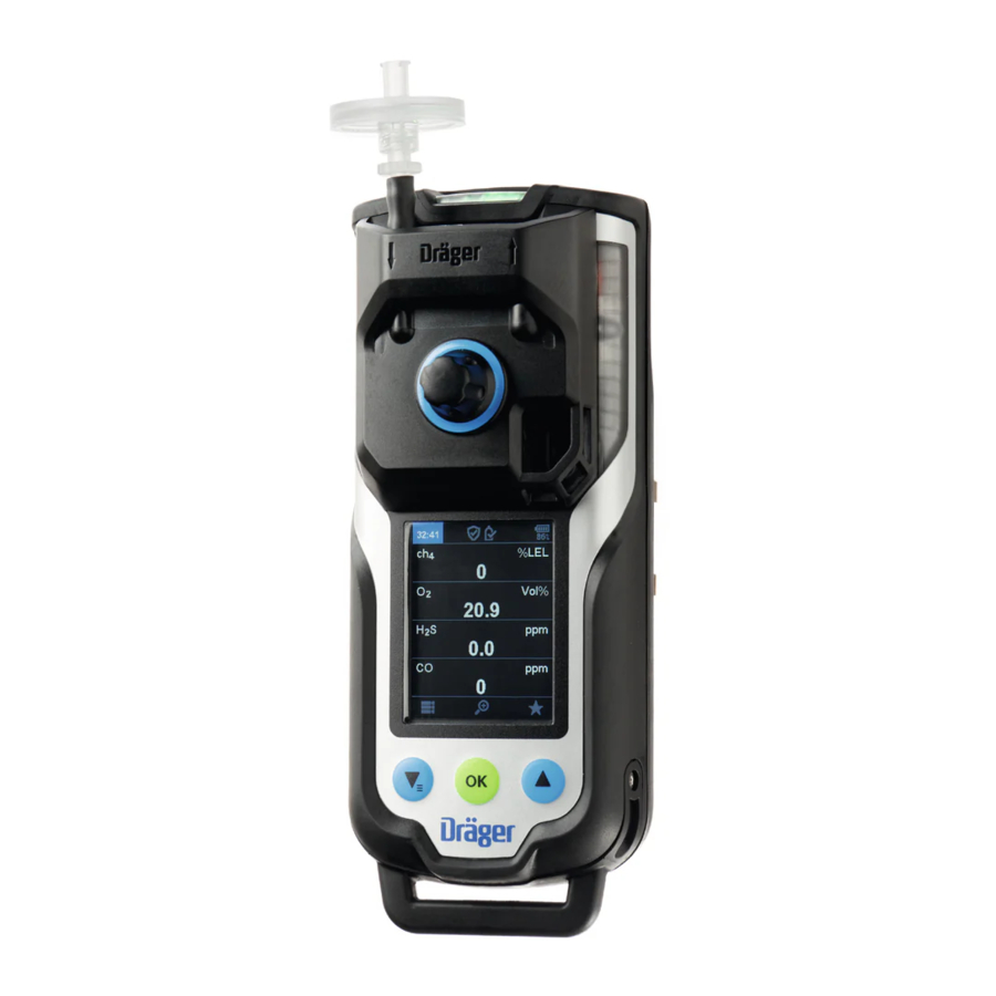
Description
Product overview
The graphics are displayed on the fold-out page.
Graphic A

- Display
- Locking screw for an additional charging module
- Power supply unit
- Charge LED green/red
- Labelling field (X-am 8000 only)
- Induction charger
Graphic B

- Gas inlets
- Thread port for pumps and calibration adapter
- Horn
- Pump outlet and inlet
Graphic C

- LED green/yellow/red
- LED yellow/red
Graphic D

- feature button 1
- Feature button 2
- Feature button 3
Graphic E

- Status information
- Navigation bar
Graphic F

- Clip (optional)
- Socket for support belt for shoulder version (X-am 8000 only)
Graphic G

- Alarm A1, continuous red light
- Alarm A2, alternating red/black light
- STEL alarm
- TWA alarm
Graphic J

- Battery pre-alarm
- Battery main alarm
Graphic K

- Calibration adapter CAL 2.0 (grey coloured ring and sticker "CAL 2.0")
- Gas inlet
- Exhaust
- Locking screw
Graphic L

- Pre-tube bracket (X-am 8000 only)
- Pre-tube (X-am 8000 only)
Graphic M1

- Pump adapter (blue coloured ring)
- Gas inlet
- Dust and water filter
- Exhaust
- Locking screw
Graphic M2

- Pump adapter "Nona" (blue coloured ring and sticker "Nona")
Intended use
Dräger X-am® 8000 is a portable gas detector for clearance measurements and for the continuous monitoring of the concentration of several gases in ambient air in the workplace and in explosion-hazard areas.
X-am 8000 can measure up to 7 gasses in accordance with the installed DrägerSensors (EC, IR, CatEx, PID). The gas detector can be operated in pump mode (if it is equipped with a pump) or in diffusion mode.
Limitations on use
The gas detector is not suitable for measuring process gasses.
Operation of the gas detector in the charging cradle in a vehicle is only permitted under the following conditions:
- Acoustic signalling must be deactivated (with the help of the PC software CC-Vision) so that the driver is not distracted.
Approvals
A copy of the name plate, the declaration of conformity and the sensor data relevant for measurement purposes are provided in the enclosed supplementary documentation (part no. 90 33 655).
Explosion protection:
BVS 17 ATEX E 040 X certifies the intended use in explosionhazard areas and the measuring function for explosion protection. PFG 19 G 001 X certifies the measurement of oxygen deficiency and oxygen surplus as well as the measuring function for toxic gases. For certified gases and measured values, see the enclosed supplementary documentation (part no. 90 33 655).
CSA-specific information:
Only the combustible gas part of this instrument has been tested for measuring accuracy.
Radio approval (X-am 8000 only):
The information for radio approval can be viewed in the menu. For further information, see the following chapter: "Opening information".
Accessories relevant to approval:
This chapter contains an overview of the key parts covered by the BVS and PFG certification. Information on other parts can be found in the spare parts list or requested from the service of Dräger. The ambient conditions that apply for the gas detector also apply for the accessories. For further information see: "Gas detector".
| Description | Part number |
| Carrying strap | 8326823 |
| Calibration adapter CAL 2.0 | 3720224 |
| Pump adapter with dust and water filter | 8326820 |
| Pump adapter "Nona" with dust and water filter | 3720225 |
| Induction charger | 8325825 |
The data logger is not part of the technical suitability test.
Label
The energy supply label has a mark for a service label. Here, a maximum of one service label and one year-point label may be attached one on top of the other. Further labels, conductive labels or labels with conductive material or parts can have a negative effect on inductive charging.
 The name plate on the gas detector and the alarm elements must not be concealed.
Sensor slots X-am 8000
| Term Sensor slot | Configuration |
| HPP 1 (High Power Port) | PID or IR sensor |
| HPP 2 (High Power Port) | IR or CatEx sensor (no Dual IR Ex / CO 2 HC) |
| EC 1-3 (Electro Chemical) | EC sensors |
Operation
Operating concept
Navigation is done with the 3 multifeature buttons and the dynamic navigation bar (see Graphic E on the fold-out page). The navigation bar changes dynamically depending on the available interactions.
Symbol explanations
Feature buttons
| Symbol | Explanation |
 | Confirm action/dialog / return to menu |
 | Confirm all |
 | Scroll up / through display |
 | Scroll down / through display |
 | Cancel action |
 | Display quick menu |
 | Display measuring channels individually |
 | Display all measuring channels |
 | Increase value |
 | Decrease value |
 | Repeat feature |
 | Display menu |
Displays
| Symbol | Explanation |
 | Horn and vibration for gas alarm deactivated |
Application
| Symbol | Explanation |
 | Measuring |
 | Clearance measurement (X-am 8000 only) |
 | Sensor selection (X-am 8000 only) |
 | Leak search (X-am 8000 only) |
 | Benzene/pre-tube measurement (X-am 8000 only) |
 | Fresh air calibration |
 | Bump test or calibration |
Device status
| Symbol | Explanation |
 | Overview of the bump test intervals activated (additional information for the D-Light feature). There are no gas alarms or errors. |
 | Monitoring of the calibration intervals activated, D-Light function deactivated (additional information for the D-Light function). There are no gas alarms or errors. |
 | Alarm message |
 | Warning message The gas detector can be operated normally. If the warning message is still displayed after operation, the gas detector requires maintenance. Menu Messages displays details. |
 | Fault message The gas detector or measuring channel is not ready to measure and requires maintenance. Menu Messages displays details. |
 | Information message Menu Messages displays details. |
 | STEL alarm message |
 | TWA alarm message |
 | Event report |
Connection
| Symbol | Explanation |
 | Maintenance mode (access to the device via PC or X-dock) |
 | Bluetooth ® activated |
 | Bluetooth ® deactivated |
 | Bluetooth ® connection established |
User level
| Symbol | Explanation |
 | User level 1 |
 | User level 2 |
 | User level 3 |
Display in gas channel
| Symbol | Explanation |
 | Bump test or calibration successful |
 | Bump test or calibration failed |
 | Measurement range exceeded |
 | Readings below the measurement range |
 | Channel error |
 | Blocking alarm |
| ##### | Value too high to be displayed |
Display of offset channels
Applies to X-am 8000 only.
| Display | Description |
| ch4+ | Hydrogen offset activated with IR channel (in this example ch4) |
| CO+ | Hydrogen compensated CO sensor XXS COH2 comp being used |
| HCN+ | ToxicTwins feature activated |
Signalling concept
Acoustic life signal
A periodic acoustic signal indicates that the device is functional. The acoustic life signal can be disabled. For further information, see the following chapter: "Activating silent mode"
Visual life signal
A periodic pulse (increasing and decreasing intensity) of the green LED indicates:
- Measurement, clearance measurement, leak search or benzene/pre-tube measurement application active
- There is no device or channel error, no gas alarm and no special state
Visual life signal with activated D-Light
An activated D-Light feature allows the user to also check and indicate compliance with certain settings:
- Evaluation of bump test intervals activated and complied with (factory setting) or evaluation of the calibration intervals active and complied with
- Usage interval complied with The D-Light feature can be activated using the Dräger CCVision PC software.
Signalling visually corresponds to the life signal.
If one of the conditions listed is not fulfilled and the D-Light is activated, the greed LED will switch on briefly at regular intervals (short flash approx. every 60 s) instead of pulsing periodically.
When transmitting device information via Bluetooth® the gas alarm is disconnected from the evaluation of the D-Light status.
Switch the gas detector on or off
Initial start-up
When the gas detector is switched on for the first time, a wizard starts. The wizard guides the user through the set-up of the gas detector:
- Language selection, if applicable
- Data format and date
- Time
Then carry out an initial calibration. For further information see: "Calibrating the gas detector".
Switching on the gas detector
- Hold down the OK button for approx. 3 s.
![]() The display shows a countdown.
The display shows a countdown.
![]() The switch-on sequence and the warm-up phase of the sensors start.
The switch-on sequence and the warm-up phase of the sensors start.
The following display appear one after the other:
- Start screen
- Firmware version
- Display test (the display alternates between black and white)
- Alarm element test (LEDs, alarm signal and vibration alarm)
- Customer-specific information screen (optional and configurable with the Dräger CC-Vision PC software)
- Alarm thresholds, STEL, TWA (if configured) and LEL factor (if available)
- Any expired bump test or calibration interval as well as early warnings (if configured)
- Measured value display
The remaining sensor warm-up time is displayed in the upper, left-hand corner in a yellow box.

Incorrect device feature/settings!
Incorrect device features/settings may result in danger to life and/or risk of explosion.
► Before every use, check whether the display elements, the alarm features and information are displayed correctly. If one of the items listed above does not feature correctly or is incorrect, do not use the gas detector and have it inspected.
The following features are active during the sensor warm-up phase:
- The measured values flash
- The yellow LED is illuminated
- A warning notice is displayed
 The gas detector is ready to measure when the measured values no longer flash and the yellow LED is no longer illuminated. The warning notice may continue to be displayed if warnings are pending. For further information see: "Opening information".
No alarms are issued during the warm-up phase!
Switching off the gas detector
- Hold down ▲ and ▼ simultaneously until the displayed countdown expires.
![]() The visual, acoustic and vibration alarms activate briefly.
The visual, acoustic and vibration alarms activate briefly.
![]() The gas detector is switched off.
The gas detector is switched off.
Or
- Select
![]() in measuring mode and confirm the dialog.
in measuring mode and confirm the dialog. - Select and confirm Switch off.
The gas detector may only be switched off without a prior sign-on if the Switch-off allowed feature is activated using the Dräger CC-Vision PC software. Factory setting: activated
The gas detector switches off automatically when it is placed in the charging cradle (factory setting). As an option, this setting can be deactivated using the Dräger CC-Vision PC software.
If the gas detector remains off for longer than 21 days and is not charged, deep sleep mode is activated. In deep sleep mode, the gas detector can no longer be switched on using the Dräger CC-Vision PC software or the Dräger X-dock. In this case, the gas detector must be switched on manually. The sensors then go through their warm-up phase.
Log user in or out
The gas detector has four configurable user levels. The user levels can be set using the Dräger CC-Vision PC software. User level 0 means that the user is not signed on. User levels 1 to 3 require a password for sign-on.
The following passwords are created by default:
| User level 1: | 0001 |
| User level 2: | 0002 |
| User level 3: | 0003 |
Dräger recommends changing the predefined passwords after initial commissioning.
Default setting:
| Feature | User level | |||
| 0 |  |  |  | |
| Bump test | - |  | - | - |
| Fresh air calibration |  | | - | - |
| Confined space measurement1 |  |  | - | - |
| Sensor selection1 | - | | - | - |
| Leak search1 | - | | - | - |
| Benzene/pre-tube measurement1 | - | | - | - |
| Settings menu2 | - |  | - | - |
| Maintenance menu2 | - |  | - | - |
| Change gas1 (only PID, CatEx, and IR sensor) | - | | - | - |
- X-am 8000 only
- Maintenance and settings menu in user level 0 are not part of the technical suitability test.
To log in a user:
- Select
![]() in measuring mode and confirm the dialog.
in measuring mode and confirm the dialog. - Select and confirmLogin.
- Enter the four-digit user level password and confirm each digit.
 in measuring mode and confirm the dialog.
To sign out a user:
- Select
![]() in measuring mode and confirm the dialog.
in measuring mode and confirm the dialog. - Select 'Sign out' and confirm the dialog.
Preparations for operation
Serious damage to health
An incorrect calibration can lead to incorrect measured values, which may result in serious damage to health.
► Before performing safety measurements, check the calibration using a bump test, adjust as necessary, and check all alarm elements. If national regulations exist, the bump test must be performed in accordance with these regulations.
► If the unit is permanently in the charging cradle while being operated, then the bump test must be carried out again after 4 weeks at the latest and also if the location of the device is changed.
Malfunction of pacemakers or defibrillators Magnets can have a negative impact preventing pacemakers and implanted defibrillators from working properly.
► Do not have calibration and pump adapters anywhere near pacemakers or implanted defibrillators (e.g. by attaching them to the shoulder strap).
► All persons concerned (e.g. persons with pacemakers)
The gas detector can be switched on again in the charging cradle and is then supplied with electrical current during operation.
- Switch on the gas detector. The current measured values are shown in the display.
- Observe warnings, error messages and special states.
- Verify that the gas inlet openings and membranes are clean, freely accessible, dry and undamaged.
- Check that the date and time are set correctly.
During operation
Danger to life and/or risk of explosion!
The following alarms indicate a danger to life and/or risk of explosion:
- A2 alarm
- STEL or TWA alarm
- Device/channel error
► Immediately leave the hazard area.
Incorrect measured values!
Only for diffusion mode: If water seals the gas inlets on the gas detector (e.g. in heavy rain or if the gas detector is submerged in water), incorrect measured values may be returned.
► With the display facing downward, shake the gas detector to remove the water.
Incorrect measured values!
A different reading may be shown if the gas detector experiences a considerable impact or a significant vibration.
► When using a CatEx or IR sensor in the gas detector, a zero-point and sensitivity calibration must be carried out after experiencing an impact load that results in a nonzero display when exposed to fresh air.
► If a deviation of the measured value from the calibration value of more than ± 5% of the reading is identified before confirming the span calibration of the CatEx sensor, the sensor must be removed from operation.
As an option, the Dräger CC-Vision PC software can be used for adjustment so that any impact detected leads to a channel error for all sensors. These channel errors are deleted after calibration. If the sensor should be irreparably damaged, then this could result in a calibration error.
Only using Bluetooth® or API applications is insufficient for raising the alarm in safety-critical applications. Raising the alarm on the gas detector is decisive. Contact Dräger for a description of the API interface.
The use of Bluetooth® function and the API application are not part of the technical suitability test.
High readings outside of the LEL display range or a protection alarm may indicate an explosive concentration.
If the concentrations of combustible gases are too high, this may be the result of a lack of O2.
The IP degrees of protection do not extend to instances in which the equipment detects a gas during or after its exposure to these conditions. In the case of dust deposits and contact with water by immersion or a jet of water, check the calibration and functional integrity of the device.
In the event of overgassing beyond the sensor's measuring range, the zero-point and the sensitivity must be checked and, if necessary, a calibration must be performed.
The PEAK, STEL and TWA evaluations are interrupted if the menu is selected or in the case of the special state of a pump leak test. For a flawless calculation of the evaluations, only operate the gas detector in normal measuring mode. Selecting the quick menu has no influence on the PEAK, STEL and TWA evaluations.
If the gas detector is used for offshore applications, it must be kept at least 5 m away from compasses.
Monitoring measuring mode
In normal measuring mode, the measured values are displayed for every measurement gas (see Graphic E on the fold-out page). The life signal sounds at regular intervals (configurable) and the green LED pulses (e.g. visual life signal or D-light feature).
If a measuring range is exceeded or not reached, the respective symbol is displayed instead of the measured value. For further information, see the following chapter: "Symbol explanations"
If, in measuring mode, a event (e.g. an alarm) occurs, the respective symbol is displayed in the status bar (after the event is acknowledged, if necessary).
Displaying the measuring channel
To display an individual measuring channel:
- Select
![]() in measuring mode.
in measuring mode. - Use ▲ or ▼ to view the individual measuring channels.
- Select
![]() to navigate to the measuring channel overview.
to navigate to the measuring channel overview.
 in measuring mode.
 to navigate to the measuring channel overview.
Opening the event report
If the gas detector is switched off and then on again, the event report is deleted.
The following events are counted and displayed: A1/A2, STEL, shocks, incorrect password entries.
To open the event report:
- Select
![]() > Info > Device information in measuring mode.
> Info > Device information in measuring mode. - Use ▲ or ▼ to scroll through the individual pages until the event report.
The symbol indicates a failed sign-on only after 5 attempts.
 > Info > Device information in measuring mode.
Activating the pump
To activate the pump in (normal) measuring mode:
- Check the sealing surfaces of the pump adapter to ensure they are undamaged.
- Place, align and tighten the pump adapter on the thread port on the top cover. Check that the pump adapter is mounted correctly. Avoid bending the pump adapter. The gas detector automatically switches to pump mode as soon as the pump adapter is mounted.
![]() The leak test starts automatically.
The leak test starts automatically. - When the leak test is displayed, the suction inlet on the probe or hose closes within 60 s and remains closed until the leak test is complete.
- Release the inlet opening.
- Leak test successful: Measurement starts.
- Leak test failed: Inspect the accessories and the pump adapter and then repeat the leak test.
- Observe the flushing times. For further information, see the following chapter: "Special features when measuring with the pump",
- Remove the pump adapter.
- After completing the measurement, make sure that the seal on the pump adapter is clean and that there are no chips of metal on the seal.
Plug the protective cap onto the pump adapter to protect the seal from damage and being deformed.
 The leak test starts automatically.
Alarms
In the event of an alarm, corresponding displays, the optical alarm, vibration alarm as well as, if necessary, the acoustic alarm are activated (configurable). For further information, see the following chapter: "Alarm settings (factory setting)"
To acknowledge an alarm:
- Select
![]() .
.
Special state
The life signal is disabled during a special state. Special states are displayed by the following visual signals:
- Yellow LED flashing – 'warm-up 1' special state
- Yellow LED continuously illuminated – general special state
No alarms are issued during a special state.
Exception: The calibration adapter is mounted in measuring mode. In this case, alarms continued to be issued as long as the measurement gas can reach the sensors.
The special state is exited by eliminating the potential error, by switching to normal measuring mode in a correctly functioning gas detector or it will switch off itself after approx. 1 minute.
Incorrect measurement!
A mounted calibration adapter blocks free gas diffusion to the sensors. Correct measured values and alarms can no longer be guaranteed.
► It is imperative to actively bump the sensors (e.g. test gas cylinder with pressure reducer, flow 0.5 L/min).
Protection alarm
The protection alarm protects the CatEx sensor.
If the measuring range is exceeded significantly at the CatEx channel (very high concentration of flammable substances), a protection alarm is triggered. This CatEx protection alarm can be acknowledged by switching the gas detector off and then on again in fresh air.
If the gas detector cannot be switched off because the A2 alarm is active and the switch-off mode in the CC-Vision is set to "Switching off not allowed during A2", remove the power pack or place the gas detector in the charging cradle and allow it to switch off automatically.
Only X-am 8000:
- This does not apply in the case of an activated full-range mode for methane and hydrogen.
- When the sensor selection wizard is used, the blocking alarm is also evaluated even when CatEx sensors are greyed out. However, the display will not show until the CatEx sensor has been activated again.
For more details, refer to the technical manual.
Deleting (application) peaks
- Select
![]() in measuring mode.
in measuring mode. - Select Clear app. peak and confirm the dialog.
 in measuring mode.
The function must be activated in the quick menu.
Alternatively, this function can also be called via the menu.
Calling the Quick Menu
The Dräger CC-Vision software can be used to save up to 6 preferred features.
The following features are default settings:
- Device information
- Night mode
- Display shift peaks
- App.peak value
- Delete app. peaks
- Messages
To open the quick menu:
- Select
![]() in measuring mode.
in measuring mode. - Select and confirm the desired feature.
Opening information
- Select
![]() > Info in measuring mode.
> Info in measuring mode.
The following options are available:
| Option | Description |
| Messages | The pending warnings and errors are displayed. For a description of the messages and remedial measures, see the technical manual. |
| Device information | Device information and information about the Bluetooth® module (optional, X-am 8000 only) is displayed (e.g. MAC address, serial number, firmware version etc.). |
| Gas statistics | The following gas statistics are available:
|
| Intervals | The following intervals are available:
|
| Capture ranges | Capture ranges are displayed (if configured). |
| Battery | The battery state of charge is displayed (large). |
| Approvals (X-am 8000 only with the Bluetooth® module) | Approval information is displayed (e-Label). |
Pairing a gas detector with a smartphone
The Bluetooth ® function is not part of the technical suitability test.
Risk of explosion
The use of an unsuitable smartphone in an explosion-hazard area may lead to the ignition of flammable or explosive atmospheres.
► The smartphone must be suitable and approved for use in explosion-hazard areas.
For specific functions, Dräger offers apps that can be installed on a suitable smartphone or tablet. A license may be required under certain circumstances.
The gas detector can be paired with a suitable smartphone via Bluetooth in order to use the optionally available Dräger CSE Connect app. The application Dräger CSE Connect is optimised for the measurement, confined space entry measurement, and benzene/pre-tube measurement wizards.
Data transmitted via Bluetooth® can be used for additional safety measures. However, the data does not replace primary on-site measures by the gas detector. The alarm on the gas detector is decisive. An important consideration is that a mobile network and WLAN reception are not always available or can be interrupted.
For detailed information on pairing via Bluetooth® also refer to the instructions for use of the smartphone used.
The Bluetooth® function may only be used in countries for which an approval exists and is not part of the certified measuring function. Contact Dräger if there are any questions about availability.
The Bluetooth® function has not been tested for operation in the charging cradle.
Contamination of the gas detector or shielding elements (e.g. protective cover or CSE case) can reduce the Bluetooth® range.
Failure of the Bluetooth® communication of the gas detector is to be expected in the vicinity of strong transmitters in the range of the 2.4 GHz band.
If the Dräger CSE Connect app is used, the gas detector always has priority with respect to measurements and the gas measured values and information need to be checked on the gas detector.
Requirements:
- The Bluetooth® module is installed in the gas detector.
- Bluetooth® is activated on the gas detector and the smartphone.
- Open the CSE Connect app and selectPairing.
- Select the gas detector X-am 8000.
![information]() If several gas detectors are within range, it may be helpful to identify the desired gas detector based on the serial number, which is printed on the gas detector. In older versions of the CSE Connect app, the gas detector can also be identified by the unique MAC address. For further information, see the following chapter: "Opening information".
If several gas detectors are within range, it may be helpful to identify the desired gas detector based on the serial number, which is printed on the gas detector. In older versions of the CSE Connect app, the gas detector can also be identified by the unique MAC address. For further information, see the following chapter: "Opening information". - Accept pairing on the smartphone.
✓ Pairing of the devices is complete.
Measurement
Special features when measuring with the pump
NOTICE
Magnetic media may be damaged!
The pump adapter and calibration adapter contain a magnet which may delete data from a magnetic stripe.
► Do not bring magnetic media (e.g. credit cards) into close proximity to the pump adapter or calibration adapter.
The pump adapter "Nona" (order no. 3720225) must be used to meet the requirements of the technical suitability test (EN 60079-29-1) for measuring the gas "Nonan" with a pump. This also achieves an optimised flushing phase.
The DrägerSensor CatEx H2 100 (order no. 3729050) should preferably be used for the regular, planned and continuous measurement of hydrogen in concentrations higher than 4 Vol%. In order to achieve the best possible measurement results, use of the Dräger "Nona" pump adapter (order no. 3720225) is recommended.
When using long hoses (from 10 m):
- Make sure the weight of the hose is supported.
- Make sure there are no kinks in the suction hose.
- The max. length of hose is 45 m (with an internal diameter of 3 to 5 mm).
- Use the dust and water separators when taking measurements with the pump (order no. 83 19 364).
- The nominal flow rate is 0.35 L/min.
- If the flow rate is < 0.3 L/min, the flow alarm with be triggered.
- Following a bump test with aggressive gases (such as biogas or chlorine), flush the pump with clean air for several minutes to extend the service life of the pump.
- Testing the response time with target gas is recommended.
The wizards are only available for X-am 8000. For DrägerSensor XXS Cl2, COCl2, O3 as well as amine and odorants, there is no wizard for clearance measurement, as these gases cannot be pumped (properly) through tubes. In addition to the gases listed above, there may also be other gases for which there are no flushing times available in the gas detector. There is no confined space entry wizard for these gases.
Flush the Dräger sampling hose or Dräger probes prior to each measurement with the gas to be measured. The flushing phase is necessary to reduce negative effects associated with the use of a sampling hose or a probe, e.g. gas transport time, memory effects, dead volume. The duration of the flushing phase depends on factors such as type and concentration of the gas or vapour to be measured as well as material, length, diameter and age of the sampling hose or probe. In addition to the flushing time, the sensor response time must be observed (refer to the instructions for use for the DrägerSensors used).
Generally, when using a sampling hose (3 mm internal diameter, new, dry, clean) with standard gasses, a typical flushing time of approx. 3 s/m is required.
Example:
The flushing time for oxygen with a 10 m hose is approx.
30 seconds. The assumed sensor response time is approx. 10 seconds in addition. Thus, the overall time before reading the gas detector is approx. 40 seconds.
A flow-rate alarm is delayed by 10 to 30 seconds depending on the length of the hose.
X-am 8000: For benzene/pre-tube measurements, the maximum hose length is 10 m.
Carrying out measurements with a pump
Requirements:
- The gas detector is equipped with a pump and is switched on.
- All installed sensors are warmed up.
- The gas detector is ready to take measurements.
- The thread port and sealing surfaces of the pump adapter need to be clean and undamaged.
- Connect the hose (3 mm internal diameter) with the dust and water filter to the inlet spout (see figure M) of the pump adapter.
- If necessary, connect a second hose (max. length: 2 m) to the outlet of the pump adapter (e.g. pump adapter "Nona", order no. 3720225) to direct the measured gas to an exhaust or outside.
- Mount the pump adapter to the gas detector. Make sure that both guide pins are in the correct grooves.
![information]() Check that the pump adapter is mounted correctly. If the pump adapter is mounted correctly, the leak test starts automatically. If the leak test does not start, the gas detector is not operational. Avoid bending the pump adapter.
Check that the pump adapter is mounted correctly. If the pump adapter is mounted correctly, the leak test starts automatically. If the leak test does not start, the gas detector is not operational. Avoid bending the pump adapter.
The gas detector automatically switches to pump mode as soon as the pump adapter is mounted.
![]() The leak test starts automatically.
The leak test starts automatically.
![information]() Dräger recommends carrying out the leak test directly before using the connected probe (hose probe, bar probe) to allow for the detection of any leaks in the entire intake system.
Dräger recommends carrying out the leak test directly before using the connected probe (hose probe, bar probe) to allow for the detection of any leaks in the entire intake system.

- When the leak test is displayed, the suction inlet on the probe or hose closes within 60 s and remains closed until the leak test is complete.
- Open the suction inlet.
- Leak test successful: The measurement starts. Observe the purging times!
- Leak test failed: Inspect the probe, hose and adapter and repeat the leak test.
- Place the probe or the end of the hose on the sampling location.

The temperature at the measurement location may deviate from the temperature in the gas detector, which may influence the measured value display. The correct functioning of the temperature correction can only be guaranteed on the gas detector.
To stop measuring with the pump:
- Loosen the screw on the pump adapter.
- Remove the pump adapter.
![]() The pump is flushed (clearly audible noise) and the gas detector automatically switches to diffusion mode.
The pump is flushed (clearly audible noise) and the gas detector automatically switches to diffusion mode. - After completing the measurement, use the protective cap designed for transport and storage of the pump adapter.
Measurements with wizards
The gas detector has wizards for easily preparing the measurements and for measurement displays optimised for the measurement.
There are wizards for the following applications:
- Confined space entry: for measuring with a probe/hose, e.g. In a container
- Sensor selection: for hiding/displaying gas channels
- Leak search: for detecting gas leaks
- Benzene/pre-tube measurement: for using pre-tubes as a filter for the PID
While the wizard loads, the gas detector is in a special state.
The wizards are not supported if the gas detector does not have the required material-specific properties for the gas to be measured, or if the gas detector is not within the permissible temperature range (typically 0 to 40°C for confined spaces and benzene/pre-tube measurements).
Carrying out confined space entry measurements with the wizard
During confined space entry measurements, the duration of the measurement (in mm: ss) is displayed for a maximum of one hour in place of the time. Afterwards, the time is displayed again. The measurement duration is restarted after each flow alarm.
Requirements:
- The gas detector is switched on.
- The user is signed in with the corresponding user level.
To carry out a confined space entry measurement:
- Sign in with the required user level, if necessary.
- Select
![]() > Confined space in measuring mode (if configured using the Dräger CC-Vision PC software). Follow the directions of the wizard.
> Confined space in measuring mode (if configured using the Dräger CC-Vision PC software). Follow the directions of the wizard.
![]() The hose length or probe selection is displayed.
The hose length or probe selection is displayed. - Select the hose length / probe.
![]() The leak test starts.
The leak test starts. - Confirm the successful leak test.
![]() The start dialog for the measurement is displayed.
The start dialog for the measurement is displayed. - Place the probe or the hose on the sampling location.
- Confirm the dialog to start the measurement.
The hose is flushed, and the remaining flushing time (flooding time) is displayed. If, during the flushing time, an alarm threshold or the permissible temperature range is exceeded, the countdown is stopped and the alarm or message is displayed.
The displayed flushing time shows the minimum wait time required for the measurement gas to reach the sensor from the sampling location in an ideal scenario. This applies to the use of a Dräger sampling hose (fluoroelastomer, brand new, dry, clean) with an internal diameter of 3 mm and telescopic probes (max. length of 2000 mm) with a sampling hose (fluoroelastomer, brand new, dry, clean) with an internal diameter of 5 mm. Other fixtures (e.g. pre-tube) extend the minimum wait time and must also be taken into consideration. The flushing time only applies to the configured measurement gas.
The flushing times recommended by the gas detector are ascertained according to the state of technology. Dräger is not liable for their use. The user is responsible for evaluating the wait time for their application. After the wait time expires, evaluation is required to determine if the measured value is stable or if the wait time was possibly insufficient. The same applies if the countdown was stopped unexpectedly.
X-am 8000: As an option, the Dräger CC-Vision PC software can be used to define a fixed flushing time (adjustment range: 30 to 900 s) which is then used by the gas detector in the wizards. The user is responsible for determining this time and using the feature. This feature can be used, for example, when a PID sensor with custom response factors is used to use this wizard.
The measurement of other gasses or vapours than the selected measurement gas per measuring channel causes additional wait time which must also be considered in addition to the minimum wait time.
The confined space entry measurement is displayed when after the flushing time is complete.
To end the confined space entry measurement:
- Select
![]() during the confined space entry measurement and confirm the dialog.
during the confined space entry measurement and confirm the dialog.
![]() A dialog for performing another confined space entry measurement is displayed.
A dialog for performing another confined space entry measurement is displayed. - Select
![]() to end the wizard.
to end the wizard. - Remove the pump adapter.
- Return to normal measuring mode.
Carrying out sensor selection with the wizard
Gas channels can be temporarily hidden with the sensor selection. This is useful if certain gases are deliberately not to be measured. The alarms of the hidden gas channels are not output and no measurement data is written to the data logger.
Dräger recommends hiding the O2 channel and all other electrochemical sensors if the DrägerSensor CatEx H2 100 is to be used to measure a concentration of hydrogen exceeding 100 %LEL. When exiting the wizard or displaying the sensors again, checking the zero-point and the sensitivity is recommended if an impact on the sensors cannot be ruled out.
Channel errors and warnings, as well as possible alarms of hidden sensors are not displayed. The evaluation of the CatEx blocking alarm remains active in the background and appears when the channel is displayed again and the blocking alarm occurred while hidden.
Requirements:
- The gas detector is switched on.
- The user is signed in with the corresponding user level.
To select the sensor:
- Sign in with the required user level, if necessary.
- Select
![]() > Select sensors in measuring mode (if configured using the Dräger CC-Vision PC software).
> Select sensors in measuring mode (if configured using the Dräger CC-Vision PC software). - Deselect sensors which are to be hidden.
- Select Next to start the measurement with the wizard and the required gas channels.
All gas channels are automatically shown again once you leave the wizard.
If an offset channel is hidden, the offsetting is interrupted.
Carrying out leak searches with the wizard
During a leak search, the duration of the measurement (in mm: ss) is displayed for a maximum of one hour in place of the time and the measured values can be displayed in the form of a bar chart (configurable with the CC-Vision PC software). Afterwards, the time is displayed again. The measurement duration is restarted after each flow alarm.
During a leak search, the Clear app. peak feature should be stored in the quick menu using the Dräger CC-Vision PC software. This feature can be used to delete the application values in the bar chart.
Because of the physical flushing times, Dräger recommends carrying out measurements with the leak search wizard without a hose/probe or with only a short hose (max. 2 m).
Requirements:
- The gas detector is equipped with a pump and is switched on.
- All installed sensors are warmed up.
- The gas detector is ready to take measurements.
To carry out a leak search:
- Sign in with the required user level.
- Select
![]() > Leak search in measuring mode.
> Leak search in measuring mode. - Confirm the successful leak test to start the measurement.
The device emits tones in the "Individual measuring channel" display which increase in frequency as the gas concentration increases. If the pre-alarm threshold is reached, the gas alarm appears.
To end the leak search:
- Select
![]() in leak search mode and confirm the dialog.
in leak search mode and confirm the dialog. - Remove the pump adapter.
- Return to normal measuring mode.
 in leak search mode and confirm the dialog.
Carrying out a benzene/pre-tube measurement with the wizard
Observe the instructions for use of the respective tube!
The use of a pre-tube is only possible when using the wizard. During the benzene/pre-tube measurement, the visual alarm, acoustic alarm, vibration alarm and alarm evaluation are deactivated.
A benzene/pre-tube measurement (photoionization detector) with a pre-tube (e.g. benzene pre-tube) can only be done with the benzene/pre-tube wizard.
During the benzene/pre-tube measurement, the gas to be measured and the PEAK values are visible on the display. All other sensors are not evaluated.
If the measured gas is changed while using the wizard, then the TWA and STEL evaluations present are reset.
For the user gases (VOC, VOC1... VOC9), no wizards are offered (apart from measuring) if there is no fixed flushing time saved in the gas detector. For further information see: "Measurement".
Mounting the pre-tube bracket
Fast temperature and humidity changes influence the measured signal. If temperature and humidity jumps are anticipated, Dräger recommends using a damp pre-tube for the measurement.
- Mount the pump adapter to the gas detector. Make sure that both guide pins are in the correct grooves.

- Connect the dust and water filter (3) to the short hose piece (4) on the pump adapter (5).

- Mount the pre-tube bracket (2) to the dust and water filter (3).
- Mount the hose or bar probe (1) to the pre-tube bracket (2) (max. hose length: 10 m).
- As necessary: Use a floating probe.
- If necessary, connect a second hose (max. length: 2 m) to the outlet of the pump adapter (e.g. pump adapter "Nona", order no. 3720225) to direct the measured gas to an exhaust or outside.


Use an adapter piece for varying hose diameters if necessary (minimum internal diameter: 3 mm).
Carrying out the measurement
A new pre-tube must be used for every single measurement or calibration with pre-tube.
Requirements:
- The gas detector is switched on.
- The user is signed in with the corresponding user level.
- Warm-up phase 1 of the PID is complete.
- The pre-tube bracket and the dust and water filter are mounted on the pump adapter.
To carry out a benzene/pre-tube measurement:
- Select
![]() > Benzene / Pre-tube in measuring mode (if configured using the Dräger CC-Vision PC software).
> Benzene / Pre-tube in measuring mode (if configured using the Dräger CC-Vision PC software).
![]() A dialog for performing the fresh air calibration is displayed.
A dialog for performing the fresh air calibration is displayed. - Carry out a fresh air calibration with an activated charcoal tube or skip this step by pressing
![]() .
. - When selecting the fresh air calibration:
- Follow the directions of the wizard.
- After a successful fresh air calibration, remove the activated charcoal tube.
- The pre-tube selection is displayed.
- Select the pre-tube.
If a benzene pre-tube is selected, the PID automatically switches to benzene. - Open the pre-tube, insert it in the pre-tube bracket (arrow marking in the direction of the gas detector; see figure L) and confirm the dialog.
![]() The hose length selection is displayed.
The hose length selection is displayed. - Select the hose length or probe.
![]() The leak test starts.
The leak test starts. - Confirm the successful leak test.
![]() The start dialog for the measurement is displayed.
The start dialog for the measurement is displayed. - Place the probe or the end of the hose on the sampling location.
- Select
![]() to start the measurement.
to start the measurement.
![]() The hose is flushed, and the remaining flushing time is displayed.
The hose is flushed, and the remaining flushing time is displayed.
The benzene/pre-tube measuring mode is displayed once the flushing time is complete.
To end the benzene/pre-tube measurement:
- Select
![]() in benzene/pre-tube measuring mode and confirm the dialog.
in benzene/pre-tube measuring mode and confirm the dialog.
![]() A dialog for removing the pre-tube appears.
A dialog for removing the pre-tube appears. - Remove the pre-tube.
![]() A dialog for a further benzene/pre-tube measurement appears.
A dialog for a further benzene/pre-tube measurement appears. - Select
![]() to end the benzene/pre-tube measurement.
to end the benzene/pre-tube measurement. - Remove the pump adapter with the pre-tube if necessary.
Configuring the device settings
Additional settings can be changed using the Dräger CCVision PC software.
To open the device settings:
- Select
![]() in measuring mode and confirm the dialog.
in measuring mode and confirm the dialog. - Sign in with the required user level, if necessary.
- Select and confirm Settings.
Activating day or night mode
- Open the device settings.
- Select and confirm Night mode / Day mode.
Changing the device language
- Open the device settings.
- Select Language.
- Select and confirm the desired language.
Setting date and time
- Open the device settings.
- Select Date & time.
- Select Set date format and then select and confirm the date format.
- Select Set date and then set and confirm the date.
- SelectSet time and then set and confirm the time.
The user must manually switch between summer and winter time.
When using the X-dock maintenance station, automatic time synchronisation is possible.
Activating silent mode
Silent mode can be activated for 15 minutes on the gas detector. When silent mode is active, vibration and the horn are deactivated. Permanent deactivation is possible using the Dräger CC-Vision PC software.
The technical suitability test expires if the silent mode is permanently activated.
Activating or deactivating the capture range
- Open the device settings.
- SelectCapture ranges.
- Activate or deactivate the capture range.
- To adopt the new setting, turn the gas detector off and back on.
Dräger recommends that you activate the capture ranges feature.
Activating or deactivating Bluetooth® (Xam 8000 only)
- Open the device settings.
- SelectBluetooth.
- Activate or deactivate Bluetooth®.
Activating full-range mode
Full-range mode is not part of the technical suitability test.
Risk of explosion!
Only for CatEx125 PR and CatEx125 PR Gas: The full-range mode only applies for methane in the air.
Only for CatEx H2 100: The full-range mode only applies for hydrogen in the air.
Any other gas composition impacts the measured signal and may cause an incorrect display.
► Only use the full-range mode to measure methane and hydrogen in the air.
The full-range mode can only be activated for the sensors
DrägerSensor CatEx 125 PR (order number 68 12 950) and CatEx 125 PR Gas (order number 68 13 080) with the measured gas methane and for DrägerSensor CatEx H2 100 with the measured gas hydrogen.
When full-range mode is activated, there is an automatic switch to the Vol% range if measured values exceed 100 %LEL.
When the "No measured values in Vol% range" feature is activated, the full-range mode in %LEL will continue to be shown instead of the measured values in the Vol% range.
When the values return to the <100 %LEL methane or hydrogen range, the measured value display alternates with the transitional phase indicator (circle arrow).
Prerequisite:
- The %LEL (heat of reaction) and Vol% (thermal conduction) measuring ranges are calibrated.
- Activate the full-range mode with the Dräger CC-Vision PC software.
- If necessary, activate the "No measured values in Vol% range" feature with the Dräger CC-Vision PC software.
Hydrogen (H2) added signal (for IR Ex)
The H2 added signal can be adjusted using the Dräger CCVision PC software.
Requirements:
- At least one DrägerSensor XXS H2 HC (68 12 025) is activated. H2 is set as the measurement gas.
- An Ex channel on the DrägerSensor DUAL IR Ex/CO2 (68 11 960) or DrägerSensor IR Ex (68 12 180) is activated.
- Both channels are set to the unit %LEL/%LEL/%LIE.
- The H2 added signal is only possible with a DrägerSensor XXS H2 HC and an IR Ex channel.
When the H2 added signal is activated, the LEL gas concentrations of both selected sensors are added together and the result is shown in the display in the place of the IR Ex display.
An activated H2 added signal is displayed with a + next to the gas name of the IR Ex sensor in the display.
Previously set alarm thresholds are maintained in order to ensure that in the presence of hydrogen (H2) the alarm of the IR Ex Channel is triggered earlier if required.
IR Ex sensor: Activating second Ex measuring channel
A second Ex measuring channel can be activated for the IR Ex sensor using the Dräger CC-Vision PC software.
An H2 offset is only possible with an IR-Ex channel (with measuring range 0 to 100% LEL).
Changing the gas
This feature is not part of the technical suitability test.
The gas change remains even after restarting the gas detector.
The measuring gas for the supported sensors can be changed on the gas detectors with this feature.
The data stored in the statistics counters are lost when the gas is changed. The Dräger GasVision PC software can be used to manually view the data via the data logger at a later point in time. Automatic notifications via the X-dock Manager may only be available to a limited extent.
Limitations to the combination of measured and calibration gas are applied based on the sensor data set.
During a calibration, all gases are calibrated with a cross calibration available in this function. Cross calibration is less accurate than target gas calibration.
Special features of IR sensor:
- The feature is not available for methane as the measured gas.
- You cannot switch from any gas to methane.
- To use methane and other Ex gases at the same time, the second Ex measuring channel can be activated. For further information see: "IR Ex sensor: Activating second Ex measuring channel".
Requirements:
- The gas detector is switched on.
- The user is signed in with the corresponding user level.
- In order to be able to use the full functionality, the test gas set for the calibration and the bump test must be the same (e.g. methane for CatEx).
To change a measured gas:
- Sign in with the required user level, if necessary.
- Select
![]() > Switch gas in measuring mode (if configured using the Dräger CC-Vision PC software).
> Switch gas in measuring mode (if configured using the Dräger CC-Vision PC software).
![]() A list of the supported sensors with the current measured gas is displayed.
A list of the supported sensors with the current measured gas is displayed. - Select sensor.
![]() A list of available measured gases is displayed.
A list of available measured gases is displayed. - Select new measured gas.
![]() Alarm thresholds and LEL factor of the new measured gas are displayed.
Alarm thresholds and LEL factor of the new measured gas are displayed. - Confirm to return to normal measuring mode.
PID substance list
A PID (photoionization detector) can be used to measure a range of substances. As soon as a substance can be ionized, it is detected by a PID sensor. Many organic substances that are considered contaminants can be measured with a PID. This particularly includes volatile organic hydrocarbons (VOCs, volatile organic compounds).
The PID substance list (order no. 9300316) can be downloaded in electronic form from the database for technical documentation ( www.draeger.com/ifu).
Maintenance
Risk of explosion!
To reduce the risk of ignition of a flammable or explosive atmosphere, observe the following:
► Do not open the gas detector in explosion-hazard areas.
Risk of explosion!
If gases that exceed the lower explosive limit are to be used, a risk assessment must be completed beforehand. The resulting safety measures must be implemented before the maintenance station is used. If the required expertise is not available, advice should be sought from other expert sources (e.g. specialists, testing institutes or manufacturers).
Danger to health!
Test gas may damage health if inhaled.
► Do not inhale the test gas. Observe the hazard warnings of the relevant Safety Data Sheets and the instructions for use of the gas detector! Observe the national regulations when defining calibration intervals.

Danger to health
Electrochemical sensors contain corrosive liquids.
► In the event of leaking, avoid contact with the skin and eyes. In case of contact, rinse thoroughly with plenty of water.
For further information about how to use the Dräger sensor, click on the following link: www.draeger.com/sensorhandbook.
Maintenance intervals
| Test | Interval |
| Inspection and maintenance by specialists. | Every 12 months |
| Check signalling elements with the signal test | Automatically each time the device is started or manually |
For inspections and maintenance, see:
- EN/IEC 60079-29-2 – Gas detectors - Selection, installation, use and maintenance of detectors for flammable gases and oxygen
- EN 45544-4 – Electrical apparatus used for the direct detection and direct concentration measurement of toxic gases and vapours – Part 4: Guide for selection, installation, use and maintenance
- National regulations
Calibration intervals
Observe the relevant specifications in the Sensor Handbook or in the instructions for use/data sheets of the DrägerSensors installed.
Recommended calibration intervals for DrägerSensors:
| DrägerSensor | Calibration interval |
| CatEx, O2, O2 PR, H2S, H2S LC, CO LC, SO2, NO2 | Every 6 months |
| IR Ex/CO2 (ES) (HC) | Every 12 months For certified measuring function: Every 6 months |
| PID HC1), PID LC ppb1) | Depending on the application conditions, daily calibration may be necessary. The interval can gradually be extended to 30 days2) if no deviations occur in the calibration during successive tests. |
| Other DrägerSensors | See the special data sheets for the respective sensors. |
- To ensure optimal functional integrity, particularly at temperatures below 0°C, Dräger recommends replacing the sensor after 3 years (from date of manufacture). 3 years corresponds with approx. 6000 operating hours when used very frequently. The age of the sensor can be determined from the serial number, refer to the additional documentation enclosed with the gas detector (part number 90 33 655).
- Alternatively, a calibration interval of 6 months can be used. This requires a daily "Advanced bump test" reading test with a tolerance of 10% of the target concentration to be carried out with the X-dock maintenance station. If this test is not passed, the gas detector must be calibrated.
Replacing, retrofitting or removing sensors, see technical manual.
Test gases
Test gas properties (e.g. relative humidity, concentration) can be found in the relevant sensor data sheet.
The relative humidity of the test gas is not relevant for O2 sensors.
Different test gases are used depending on the type of calibration.
Carrying out bump tests
The bump test can be performed as follows:
- Bump test with the wizard (quick bump test)
- Bump test with X-dock (quick or extended bump test)
Dräger recommends using the extended bump test for cross calibrations (see the Dräger X-dock instructions for use).
X-am 8000: If the gas detector is equipped with a PID sensor, Dräger recommends not to use the Nonane tester (order no. 83 25 61) for the bump test because of the long saturation time of the PID sensor.
For bump tests with the wizard and the X-dock, the results are saved in the device memory.
Carrying out bump tests with the wizard
Health hazard from test gas
Breathing in of test gas can be harmful to health or lead to death.
► Do not inhale the test gas.
► Observe risks connected with the test gas, hazards notes and safety advice (see for example safety data sheets, instructions on the testing media).
Incorrect alarm behaviour!
A closed gas path causes incorrect measured values. This may cause alarms to be triggered incorrectly.
► Never close the outlet of the calibration adapter.
Dräger recommends a test gas concentration of <60 %LEL for CatEx and IR sensors and a measuring range of 0% to 100 %LEL.
Dräger recommends selecting a test gas concentration in the middle of the respective measuring range or close to the expected measured value.
A bump test with the wizard is always carried out with the measured gas configured on the gas detector.
Requirements:
- A bump test can only be carried out if at least one sensor has been configured for the bump test with the Dräger CCVision PC software.
- The gas detector is switched on and warm-up phase 1 is complete.
- The thread port and sealing surfaces of the pump and calibration adapter need to be clean and undamaged.
- A suitable test gas cylinder is available, e.g. a test gas cylinder (order no. 68 11 130) with the following mixed gas ratios: 50 ppm CO, 15 ppm H2S, 2.5 Vol% CH4, 18 Vol% O2
Other test gas cylinder can be added upon request.
To carry out a bump test with the calibration adapter:
- Mount the calibration adapter to the gas detector. Make sure that both guide pins are in the correct grooves. Avoid putting the pump adapter at the wrong angle.
![information]() Alternatively the pump adapter can be used with an ondemand valve.
Alternatively the pump adapter can be used with an ondemand valve.
![]()
- Connect the hose to the test gas cylinder and the inlet on the calibration adapter.
- If needed, connect a second hose (max. length: 2 m) to the outlet on the calibration adapter to direct the test gas to an exhaust or outside. Make sure that these is sufficient ventilation in room or vehicles.
- Open the bump test (depending on the configuration).
- Select
![]() > Maintenance > Bump test (if configured using the Dräger CC-Vision PC software).
> Maintenance > Bump test (if configured using the Dräger CC-Vision PC software). ![]() > Login
> Login
Enter and confirm the password.
Select Maintenance > Bump test.
- Select
- Open the valve on the test gas cylinder, the volume flow must be 0.5 L/min and the gas concentration must be higher (lower with oxygen) than the alarm threshold concentration that is to be tested.
- Select
![]() to start the bump test.
to start the bump test.
![]() All measuring channels which are included in the bump test flash, and all others are greyed out. When a measuring channel successfully passes the test,
All measuring channels which are included in the bump test flash, and all others are greyed out. When a measuring channel successfully passes the test, ![]() appears.
appears. - The bump test is complete when all measuring channels included in the test successfully passed or failed the test.
- Close the valves on the test gas cylinder.
- Select
![]() and then confirm the dialog to discard the result.
and then confirm the dialog to discard the result. - Select
![]() to confirm the result.
to confirm the result.
- Select
- Remove the calibration adapter.
- After completing the measurement, make sure that the seal on the calibration adapter is clean and that there are no chips of metal on the seal.
Plug the protective cap onto the calibration adapter to protect the seal from damage and being deformed.

 and then confirm the dialog to discard the result.
 to confirm the result.
If there was an error during the bump test:
- An error is displayed for the measuring channel.
- Repeat the bump test.
- If necessary, replace the sensor.
Checking response time (t90)
- Carry out a bump test and a simplified check of the response time.
- Connect the test gas to the calibration adapter and open the test gas cylinder valve to flush the calibration adapter with the test gas.
- Place the calibration adapter on the gas detector and determine the start time.
- Determine the time until up to 90% of the test gas concentration has been reached.
- Compare the measured response time with that of previous bump tests and with the t90 values indicated in the enclosed supplementary documentation (part no. 9033655).
The T90 setup time determined may deviate from the certified setup time, as this simplified process is not standardcompliant.
Calibrating the gas detector
Incorrect measured values!
An incorrect calibration may prevent alarms from triggering, or alarms may trigger late.
► Do not close the outlet of the calibration adapter / exhaust gas hose.
► Always carry out the fresh air / zero calibration before the span calibration.
NOTICE
Damage to the sensors!
When using the exhaust gas hose, the sensors may be damaged in the case of direct suction on the exhaust gas hose.
► If necessary, lead the exhaust gas hose (max. length 2 m) to an exhaust of outside.
If measurement gas or calibration gas is changed, the affected channel must be calibrated.
Observe the following notices for the calibration:
- For the fresh air calibration of Dräger IR sensors for explosive hydrocarbon, it is assumed that the change in the zero-point leads to a change of less than or equal to ±5 %LEL of the measured value at 50 %LEL. If the deviation is greater than ±5 %LEL, the span calibration is invalid.
- For the zero-point calibration of Dräger IR sensors, it is assumed that the change in the zero-point leads to a change of less than or equal to ±5 %LEL or 0.05 Vol% CO2 of the measured value at 50 %LEL or 0.5 Vol% CO2.
If the deviation is greater than ±5 %LEL or 0.05 Vol% CO2, the span calibration is invalid and an error or a warning is displayed (configurable). - For a span calibration of Dräger IR sensors, it is assumed that a valid zero-point calibration exists (no more than 30 min. old), otherwise an acknowledgeable warning is displayed.
Calibration may not be possible due to instrument and channel errors.
Fresh air calibration
To improve accuracy, a fresh air calibration must be carried out if a zero deviation exists.
Observe the following notices for the calibration:
- For the fresh air calibration of Dräger IR sensors for explosive hydrocarbon, it is assumed that the change in the zero-point leads to a change of less than or equal to ±5 %LEL of the measured value at 50 %LEL. If the deviation is greater than ±5 %LEL, the span calibration is invalid.
- For the fresh air calibration, the display on the XXS O2 and XXS O2 PR is set to 20.9 Vol%.
X-am 8000:
- An activated H2 added signal is automatically deactivated duration of a bump test or a calibration.
- During fresh air calibration, the zero-point of all sensors (except the DrägerSensors XXS O2, XXS O2 PR, DUAL IR CO2 and IR CO2, XXS O3) is set to 0.
- The DrägerSensors DUAL IR CO2, IR CO2 and XXS O3 must be calibrated with a suitable gas which is free of carbon dioxide / ozone (e.g. N2).
- The DrägerSensor PID LC ppb can be calibrated with the zero gasses nitrogen or synthetic air.
Requirements:
- Fresh air calibration can only be carried out if at least one sensor supports the fresh air calibration.
- The fresh air must be free of measured or interfering gases.
- The gas detector is switched on and warm-up phases 1 and 2 are complete.
To carry out a fresh air calibration:
- Switch on the gas detector.
- Call up the fresh air calibration (depending on the configuration):
If the fresh air calibration was released for user level 0 by the Dräger CC-Vision PC software:- Select
![]() > Maintenance > Fresh air cal..
> Maintenance > Fresh air cal..
If the fresh air calibration was not released for user level 0 by the Dräger CC-Vision PC software:![]() > Login
> Login- Enter and confirm the password.
- Select Maintenance > Fresh air cal..
- Select
- Select
![]() to start the fresh air calibration.
to start the fresh air calibration.
![]() All measuring channels which are included in the fresh air calibration flash, and all others are greyed out. The result is displayed as follows for every measuring channel:
All measuring channels which are included in the fresh air calibration flash, and all others are greyed out. The result is displayed as follows for every measuring channel:
![]() fresh air calibration successful.
fresh air calibration successful.
![]() fresh air calibration failed.
fresh air calibration failed. - If necessary, press
![]() to overrule the stability control. In this case, a calibration takes place immediately.
to overrule the stability control. In this case, a calibration takes place immediately.
![information]() Dräger recommends using the automatic stability control (wait until the gas detector has automatically carried out the calibration).
Dräger recommends using the automatic stability control (wait until the gas detector has automatically carried out the calibration).
![]() The new measured value is displayed for control purposes.
The new measured value is displayed for control purposes.
The result is displayed as follows:
![]() fresh air calibration successful.
fresh air calibration successful.
![]() fresh air calibration failed.
fresh air calibration failed. - The fresh air calibration is complete when all participating measurement channels have passed or failed the fresh air calibration.
- Select
![]() and then confirm the dialog to discard the result.
and then confirm the dialog to discard the result. - Select
![]() to confirm the result.
to confirm the result.
- Select
 fresh air calibration failed.
If there was an error during the fresh air calibration:
- Repeat the fresh air calibration.
- If necessary, replace the sensor.
Carrying out a single-gas calibration
Please note the following in relation to the single-gas calibration:
- For a single-gas calibration, you can choose either the zero-point calibration and span calibration.
- With a zero-point calibration, the zero-point of the selected sensor is set to zero.
- With the zero-point calibration, it is assumed for Dräger IR sensors that the change to the zero-point is less than or equal to ±5 %LEL or 0.05 Vol% CO2 of the measured value at 50 %LEL or 0.5 Vol% CO2. If the deviation is greater than ±5 %LEL or 0.05 Vol% CO2, the span calibration will be invalid and an error or warning will be issued (configurable).
- With a span calibration, it is assumed for Dräger IR sensors that there is a valid zero-point calibration (no older than 30 min), otherwise an acknowledgeable warning will be issued.
- With a span calibration, the sensitivity of the sensor selected is set to the concentration value of the test gas.
When implementing an active over range with the CatEx sensor (measurement gas: methane) note the additional information in the technical manual.
Use a standard test gas.
Allowed test gas concentration:
| DUAL IR CO2 1 (ES) IR CO2 1 (ES) | 0.05 to 5 Vol%2 |
| DUAL IR Ex1 (ES) IR Ex1 (ES) CatEx125 PR CatEx125 PR Gas CatEx H2 1001 O2 , O2 PR H2S H2 HC 1 | The permitted test gas concentrations are shown by the gas detector during the single-gas calibration of the sensitivity. |
| Dual IR Ex/CO 2 HC (CO 2 channel) 1 | 20 to 80 Vol% |
| PID HC 1 | 100 ppm iBut |
| PID LC ppb 1 | 5 ppm iBut |
Test gas concentration of other gasses:
Refer to the Dräger CC-Vision PC software
- Only X-am 8000
- Depending on the measuring range and the measuring accuracy.
Dräger recommends selecting a test gas concentration in the middle of the respective measuring range or close to the expected measured value.
To carry out a single-gas calibration:
- Mount the calibration adapter to the gas detector. Make sure that both guide pins are in the correct grooves. Avoid putting the pump adapter at the wrong angle.
- Connect the test gas cylinder to the calibration adapter.
- Connect a second hose (max. length: 2 m) to the second connector on the calibration adapter to direct the test gas to an exhaust or outside.
- Switch on the gas detector.
- Select
![]() > Login.
> Login. - Enter and confirm the password.
- SelectMaintenance > Single gas cal..
![]() A dialog for selecting the measuring channel to be calibrated appears.
A dialog for selecting the measuring channel to be calibrated appears. - Select the measuring channel.
![]() A dialog for selecting the calibration appears.
A dialog for selecting the calibration appears. - Select either zero-point calibration or span calibration.
- For a span calibration: Enter and confirm the calibration concentration.
- Open the valves on the test gas cylinder.
- Select
![]() to start the single-gas calibration or select
to start the single-gas calibration or select ![]() to cancel the calibration.
to cancel the calibration.
![]() The measuring channel appears, and the measured value flashes.
The measuring channel appears, and the measured value flashes.
As soon as the stability check detects a stable measured value, a calibration is carried out automatically. - If necessary, press
![]() to overrule the stability control. In this case, a calibration happens immediately.
to overrule the stability control. In this case, a calibration happens immediately.
![]() The new measured value is displayed for control purposes.
The new measured value is displayed for control purposes.
The result is displayed as follows:
![]() single-gas calibration successful.
single-gas calibration successful.
![]() single-gas calibration failed.
single-gas calibration failed. - The single-gas calibration is complete when measuring channel successfully passed or failed the single-gas calibration.
- Select
![]() and then confirm the dialog to discard the result.
and then confirm the dialog to discard the result. - Select
![]() to confirm the result.
to confirm the result.
- Select
- Close the valves on the test gas cylinder.
- Remove the calibration adapter.
- After completing the measurement, make sure that the seal on the calibration adapter is clean and that there are no chips of metal on the seal.
Plug the protective cap onto the calibration adapter to protect the seal from damage and being deformed.
If there was an error during the single-gas calibration:
- Repeat the single-gas calibration.
- Inspect the sealing contours and surfaces on the calibration adapter as well as the front cradle of the housing to make sure they are free of damage. Inspect the thread port for the calibration adapter.
- If necessary, replace the sensor.
For mixed gas and cross calibration, see the technical manual.
Charging the battery
Risk of explosion!
To reduce the risk of ignition of a flammable or explosive atmosphere, observe the following:
► Do not open the gas detector in explosion-hazard areas.
► Only use the LBT 02** (lithium-ion) battery type.
► Do not charge or exchange the battery in explosionhazard areas.
► Only use the battery charger specified by Dräger. The use of a different charger nullifies the explosion protection certification of the gas detector.
Refer to the Technical Manual when replacing the battery.
The battery is a part of the lower part of the casing. The battery can be charged with or without the gas detector.
- 1. Place the gas detector or only the lower part of the casing with the battery in the charging cradle.
![]() The gas detector switches off automatically (default setting). The green LED on the power pack flashes.
The gas detector switches off automatically (default setting). The green LED on the power pack flashes.
The typical charging time after a work shift of 8 – 10 h is approx. 4 h.
The typical charging time for an empty battery is approx. 10 h.
If the battery is exhaustively discharged, it may be necessary to leave the device charging in the charging cradle for up to 16 h.
If the specified temperature range (5 to 35°C) is not reached or is exceeded, charging stops automatically. This extends the charging time. After a return to the temperature range, charging continues automatically.
No measurement!
If there is a voltage dip in the power supply lasting longer than 1 s during operation of the gas detector in the charging cradle, the gas detector will switch off.
► Ensure there is an uninterruptible power supply (this does not apply if the optional setting that the gas detector does not automatically switch off in the charging cradle is selected). If this cannot be guaranteed, check regularly that the gas detector is switched on (e.g. using the visual and acoustic life signal).
| Designation and description | Order no. |
| Inductive charging cradle for charging 1 gas detector | 83 25 825 |
| Adapter for the plug-in power supply unit | 83 25 736 |
| Plug-in power supply unit for charging 1 gas detector | 83 16 997 |
| Plug-in power supply unit for charging 5 gas detectors | 83 16 994 |
| Plug-in power supply unit 100-240 V AC; 1.33 A for charging up to 5 gas detectors (requires adapter 83 25 736) | 83 21 849 |
| Plug-in power supply unit 100-240 V AC; 6.25 A for charging up to 20 gas detectors (requires adapter 83 25 736) | 83 21 850 |
| Vehicle connection 12 V / 24 V for charging 1 gas detector | 45 30 057 |
| Vehicle connection 12 V / 24 V for charging up to 5 gas detectors (requires adapter 83 25 736) | 83 21 855 |
| Vehicle mount (requires adapter 83 25 736 and vehicle connection 83 21 855) | 83 27 636 |
Cleaning
The gas detector does not require any special care.
If it is heavily soiled, wash the gas detector with cold water and use a sponge if necessary. Dry the gas detector with a cloth.
NOTICE
Damage to the gas detector!
Harsh cleaning utensils (e.g. brushes), detergents and solvents can destroy the dust and water filters.
► Only clean the gas detector with cold water and, where necessary, a sponge.
► If the gas inlets are protected by the pump adapter, then a soft brush can also be used to clean the device. After cleaning, make sure that the gas inlet is free.
The shoulder strap can be cleaned with water and without cleaning agents in a wash bag in an (industrial) washing machine.
Device settings
Only trained and qualified personnel may change the device settings.
For more details, refer to the technical manual.
Factory settings
Different settings can be selected to meet customer requirements on order. The setting can be checked and changed with the Dräger CC-Vision PC software.
The changed parameter settings must be checked at the gas detector once transmitted in order to ensure they were transmitted correctly.
Parameters that are not visible on the gas detector must be read out and checked for changes using the Dräger CCVision PC software.
| Function | Setting |
| Fresh air calibration without password | On |
| Bump test without password | Off |
| Life signal | On |
| Switch off allowed | On |
| Capture range1) | On |
| LEL factor2) ch4 (methane) H2 (hydrogen) | 4.4 Vol% (corresponds to 100 %LEL) 4.0 Vol% (corresponds to 100 %LEL) |
| STEL | STEL feature – inactive; average duration = 15 minutes |
| TWA | TWA feature – inactive; average duration = 8 hours |
| Alarm threshold configuration | ATEX compliant |
| Alarm A1 | Acknowledgeable, non-latching, pre-alarm, increasing measured value (for O2 sensors, decreasing measured value as well) |
| Alarm A2 | Non-acknowledgeable, latching, main alarm, increasing measured value (for O2 sensors, decreasing measured value as well) |
| Symbol for type of danger | On |
| Expired bump test interval | Warning |
| Expired calibration interval | Channel warning |
| Power-save mode display | Off |
- The set capture range can be read out and selected or disabled at the gas detector. The capture range is activated in measuring mode at the factory. The capture range is always disabled in calibration mode.
- An LEL factor can be adapted to national regulations using the Dräger CC-Vision PC software.
The following factory settings are only available for the X-am 8000:
| Function | Setting |
| Bluetooth ® (if installed) | Off |
| ToxicTwins (HCN) | Off |
| No measured values in the Vol% range | Off |
Device and sensor settings
| Name: | Area / setting |
| Device settings: | |
| Password(s) | Numerical range (4-digit) |
| Acoustic life signal | Yes / No |
| Switch-off mode | "Switch off allowed" or "Switch off forbidden" or "Switch off forbidden in A2" |
| Short-term exposure limit | 0 – 60 (in minutes, setting for |
| (STEL) 1)2) | exposure alarm) |
| Shift length (TWA) 3 | 60 - 1440 (in minutes, setting for exposure alarm) |
| Alarm threshold configuration 4 | ATEX compliant/advanced |
| Sensor settings: | |
| A1 alarm: Latching Acknowledgeable | On/Off On/Off |
| A2 alarm: Acknowledgeable | On/Off |
| Alarm threshold A1 increasing (in measurement module) | 0 to A2 |
| Alarm threshold A2 increasing (in measurement module) | A1 to full scale deflection |
| Alarm threshold A1 decreasing (in measurement module, only O 2 sensors) | A2 decreasing to A1 increasing |
| Alarm threshold A2 decreasing (in measurement module, only O 2 sensors) | 0 to A1 decreasing |
| Evaluation type 1 | Inactive TWA, STEL, TWA+STEL |
| Alarm threshold STEL (in measurement module) 1 | 0 – full scale deflection |
| Alarm threshold TWA (in measurement module) 1 | 0 – full scale deflection |
- Evaluated only if the sensor is intended for this purpose.
- Corresponds to the averaging time and is used to calculate the STEL exposure level.
- Corresponds to the averaging time and is used to calculate the TWA exposure level.
- Deactivation of the ATEX-compliance leads to the loss of the technical suitability test.
Alarm settings (factory setting)
Definition:
Pre-acknowledgement: If, during the alarm condition, the acknowledgement is actuated (by pressing the OK button), the audible alarm and the vibration are switched off. The alarm is only fully reset (LED and display) once the alarm condition no longer exists.
Acknowledgement: If an acknowledgement is actuated when the A1 alarm condition no longer exists (by pressing the OK button), all alarm elements will be reset.
If the A2 and A1 alarms are configured as acknowledgeable, a pre-acknowledgement or acknowledgement of the A2 alarm will pre-acknowledge the A1 alarm or fully acknowledge it if no further alarm condition exists.
Explanation of symbols:
 : Feature activated
 : Pre-acknowledgement
| Alarms / Events | Representation in display | Latching | Acknowledgeable | LEDs | Horn | Vibration |
| A1 ↑ (increasing) | A1 | - |  |  | | |
| A2 ↑ (increasing) | A2 | | - |  | | |
| A1 ↓ (decreasing) | A1 | - | | | |  |
| A2 ↓ (decreasing) | A2 | | - | | | |
| STEL1)2) | STEL | | - | | | |
| TWA3) | TWA | | - | | | |
| Error4) | ||||||
| Battery pre-alarm5) | - | - | | | | |
| Battery main alarm6) | - | - | - | | | |
| Device error | - | | | | | |
| Channel error |  | - | | - | - | - |
- The STEL alarm can be triggered with a delay of max. 1 minute.
- After this alarm, the deployment of personnel is subject to the relevant national regulations.
- A TWA alarm can only be reset by switching the gas detector off and then on again.
- For troubleshooting, see the Technical Manual.
- The battery still lasts approx. 20 minutes after the battery pre-alarm triggers.
- The gas detector switches off automatically 20 s after a battery main alarm.
Transport
The gas detector contains lithium-ion batteries. During transport, in particular air transport of the gas detector, adhere to the relevant safety regulations and markings for lithium batteries.
After completing the measurement, use the protective cap designed for transport and storage of the pump and calibration adapter.
Storage
Dräger recommends storing the gas detector in the charging cradle.
The sensors are supplied with power even when the gas detector is switched off to ensure a faster warm-up time when switching on.
When storing the gas detector outside of the charging cradle, power supply to the sensors is cut off automatically after 21 days. When the gas detector is switched on again, there is an increased warm-up time.
For calibration adapter CAL 2.0 (3720224) and pump adapter "Nona" (3720225) the following applies:
For storage, disconnect the pump and calibration adapter from the gas detector and store it separately with the designated protective cap. This applies in particular if the gas detector is used in low temperatures (below 0°C) or if use is planned at below 0°C.
Technical data
Gas detector
| Ambient conditions: | |
| during operation and storage | -20 to +50°C 700 to 1300 hPa (measuring function) 800 to 1100 hPa (use in explosion-hazard areas) 10 to 90% (briefly up to 95%) rel. hum. |
| Degree of protection | IP 681) |
| Alarm volume | Typically 100 dB (A) at a distance of 30 cm |
| Orientation | Any |
| Gas detector storage time | 1 year |
| Sensor storage time | The ambient conditions and the storage time for sensors in their original packaging correspond to those of the gas detector |
| Flow direction of air in diffusion operation | As part of the technical suitability test: ≤6 m/s |
| Battery | Lithium-ion battery, rechargeable, 3.6 V, 6.4 Ah, 24 Wh, 250 g |
| Dimensions | approx. 179 x 77 x 42 mm (H x W x D) |
| Weight (without pump) | Typically 495 g depending on the which sensors are equipped, without transport harness |
| Weight (with pump) | Typically 550 g, depending on which sensors are equipped, without transport harness |
| Update interval for the display and signals | 1 s |
| Bluetooth ® range Bluetooth ® range with protective cover (order no. 83 25 858) | Approx. 10 m (line of sight) Approx. 5 m (line of sight) |
- Tested without the pump or calibration adapter.
Operating time in normal conditions (diffusion mode)1):
| With IR and 3 EC sensors | Typically 22 h |
| With CatEx, PID and 3 EC sensors | Typically 17 h |
| With CatEx, IR and 3 EC sensors | Typically 12 h |
| With IR, PID and 3 EC sensors | Typically 16 h |
| With PID | Typically 42 h |
- The nominal operating time of the gas detector at an ambient temperature of 20 to 25°C, 1013 mbar, alarms less than 1% of the time, power-save mode display activated. The actual operating time varies depending on the ambient temperature and pressure and battery and alarm conditions.
In pump mode: If the gas detector is used permanently in pump mode, the operating time is reduced by approx. 2 h.
Safety-related information
Information on safety notes and warnings
Safety notes and warnings warn of dangers and provide instructions for the safe use of the product. Failure to observe these safety notes and warnings may result in personal injury or damage to property.
Safety notes
This document contains sections with safety notes which warn of dangers. The type of danger and the consequences following failure to observe the safety note are included in every safety note.
Warnings refer to steps of a task and warn of dangers which may result while the steps are executed. Warnings appear before the steps.
Basic safety information
- Before using the product, carefully read through these instructions for use, the instructions for use provided with the associated products and the general instructions for use for sensors (9023657).
- Strictly follow the instructions for use. The user must fully understand and strictly observe the instructions. Use the product only for the purposes specified in the Intended use section of this document.
- Do not dispose of the instructions for use. Ensure that they are retained and appropriately used by the product user.
- Only trained and competent users are permitted to use this product.
- Comply with all local and national rules and regulations associated with this product (e.g. IEC 60079-14, EN 60079-29-2, EN 45544-4, IEC 62990-2).
- Only specialist, trained personnel are permitted to check, repair and maintain the product as described in these instructions for use and the technical manual. Further maintenance work that is not detailed in these instructions for use or in the technical manual must only be carried out by Dräger or personnel qualified by Dräger. Dräger recommend a Dräger service contract for all maintenance activities.
- Only use genuine Dräger spare parts and accessories when performing maintenance work, or the proper functioning of the product may be impaired.
- Do not use a faulty or incomplete product. Do not modify the product.
- Notify Dräger in the event of any component fault or failure.
- Substitution of components may impair the intrinsic safety of the product.
- Electrical pairing with devices which are not listed in these instructions for use should only be done following consultation with the respective manufacturers or an expert.
Use in areas subject to explosion hazards
To reduce the risk of ignition of a flammable or explosive atmosphere, strictly observe the following warnings:
Use in areas subject to explosion hazards
Devices or components for use in explosion-hazard areas which have been tested and approved according to national, European or international explosion protection regulations may only be used under the conditions specified in the approval and with consideration of the relevant legal regulations. The devices or components may not be modified in any manner. The use of faulty or incomplete parts is forbidden. The appropriate regulations must be observed at all times when carrying out repairs on these devices or components.
X-am 8000: Increased hydrogen concentrations within the measuring range of the DrägerSensor XXS H2 HC may result in false alarms due to the additive effect on DrägerSensors XXS H2S and XXS CO, XXS H2S-LC and XXS CO-LC as well as due to the negative effect on DrägerSensor XXS O2 and XXS O2 PR.
X-am 8000: Increased hydrogen concentrations within the measuring range of the DrägerSensor CatEx H2 100 may briefly influence the Dräger sensors XXS H2, XXS H2 HC, XXS H2S, XXS O2 and lead to incorrect measured value displays and false alarms. Other electrochemical sensors from Dräger may be impaired in the longer term, which is why they must not be used together with a DrägerSensor CatEx H2 100.
Oxygen enriched atmospheres
Explosion protection is not ensured in oxygen enriched atmospheres (>21 Vol% O2).
 Remove the device from the explosion-hazard area.
Oxygen deficient atmospheres
The CatEx sensor may display false readings and incorrect measured values when used for measurements in an oxygen deficient atmosphere (<12 Vol% O2). In this case the CatEx sensor cannot provide a reliable measurement.
► The CatEx sensor is intended for the measurement of flammable gases and vapours mixed with air (i.e. O2 content ≈ 21 Vol%). If the O2 content falls below 12 Vol% and an operational O2 sensor is available in the gas detector, a channel error is triggered on the CatEx channel due to oxygen deficiency. This does not apply in thermal conduction mode in the measuring range up to 100 Vol%.
A DrägerSensor CatEx125 PR or CatEx125 PR Gas should preferably be operated with an active DrägerSensor XXS O2 or O2 PR so that oxygen deficiency can be evaluated by the gas detector.
► Remove the gas detector from the area and discontinue measurement.
Incorrect calibration
An incorrect calibration leads to incorrect measured values.
► CSA requirement (Canadian Standard Association): The sensitivity must be checked daily before first using the device, with a known concentration of the gas to be measured that corresponds to 25 to 50% of the final concentration. The accuracy must be 0 to +20% of the actual value. The accuracy can be corrected by calibration.
RFID tag (optional)
► The RFID tag must not be read out in explosion-hazard areas.
NOTICE
Damage to the CatEx sensor!
Fractions of catalytic poisons in the measuring gas (e.g. volatile silicon, sulphur, heavy metal compounds or halogenated hydrocarbon) can damage the Cat Ex sensor.
► If the CatEx sensor can no longer be calibrated to the target concentration, replace the sensor.
DrägerSensor CatEx 125 PR (6812950) and CatEx 125 PR Gas (6813080)
► For this gas detector, only use sensors with serial numbers > ARLB XXXX (starting with date of manufacture in February 2018). These sensors are certified for use in zone 0, T4.
When using the PID sensor
► To ensure safe operation, the gas detector must not be switched on at temperatures below -10°C when using the PID sensor (6813475/6813500).
Conventions in this document
Meaning of the warning notes
The following warning notes are used in this document to notify users of possible dangers. The meanings of the warning notes are defined as follows:
| Alert icon | Signal word | Consequences in case of nonobservance |
 | | Indicates a potentially hazardous situation. If not avoided, it could result in death or serious injury. |
 | | Indicates a potentially hazardous situation. If not avoided, it could result in physical injury. It may also be used to alert against unsafe practices. |
| NOTICE | Indicates a potentially hazardous situation. If not avoided, it could result in damage to the product or environment. |
Typographical conventions
| Text | Text in bold identifies labels on the device and text on the display. |
| ► | This triangle in warnings identifies the options available for avoiding the hazard. |
| > | The greater-than symbol identifies a navigation path in a menu. |
| | This symbol indicates information that may make the use of this product easier. |
Glossary
| Term | Description |
| Life signal | A periodic optical (green LED) and/or acoustic signal. |
| Measurement mode | Measurement in one of the applications (measurement, clearance measurement, leak search, benzene/pre-tube measurement) (only X-am 8000). |
| Measurement | Monitoring without pump (diffusion) Monitoring with pump (with pump adapter) |
| Capture range | The capture range refers to a measured value range within which minor variations in measured values (such as signal noise, variations in concentration) do not cause variations in the display. Measured values outside the capture range will be displayed with the actual measured value. |
| Confined space entry wizard | Measurement with pump and any accessories (e.g. hose, probe) for clearance measuring areas (only X-am 8000). |
| Leak search wizard | Leak search measurement (only X-am 8000) |
| Benzene/pretube wizard | Benzene/pre-tube measurement (only Xam 8000) |
| Peak | Peak value |
| Quick bump test | Test for alarm triggering. |
| Extended bump test | Test for accuracy and alarm triggering. |
| Special state | If a special state is signalled, the user is not warned of gas concentrations which may be dangerous. The following device features are special states: Initial setup/configuration with the PC, switch-on sequence, menu, preparation phase of the wizards, maintenance wizard bump test and calibration, warm-up 1 of the sensors, device error, measuring channel error. |
| D-Light | The D-Light feature allows the user to check and indicate compliance with certain settings. |
| Physical sensors | The CatEx, IR, and PID sensor types are designated as physical sensors. There are also the electrochemical sensors. |
Abbreviations
| Abbreviation | Explanation |
| A1 | Pre-alarm |
| A2 | Main alarm |
| API | Application programming interface |
| CSE | Confined space entry, clearance measurement (before entering confined spaces) |
| IR | Infrared |
| PID | Photoionization detector |
| STEL | Short time exposure limit, threshold of an exposition over a short period of time (generally 15 minutes). |
| TWA | Time weighted average, average shift values are generally limited to eight hours exposure per day per workplace for 5 days a week during a work lifetime. Observe the national definition of the occupational exposure limit. |
Documents / ResourcesDownload manual
Here you can download full pdf version of manual, it may contain additional safety instructions, warranty information, FCC rules, etc.
Advertisement


Need help?
Do you have a question about the X-am 8000 and is the answer not in the manual?
Questions and answers