
Related Manuals for Cisco ISA500 Series


Summary of Contents for Cisco ISA500 Series
- Page 1 ADMINISTRATION GUIDE Cisco Small Business ISA500 Series Integrated Security Appliance...
- Page 2 Cisco and the Cisco Logo are trademarks of Cisco Systems, Inc. and/or its affiliates in the U.S. and other countries. A listing of Cisco's trademarks can be found at www.cisco.com/go/trademarks. Third party trademarks mentioned are the property of their respective owners. The use of the word partner does not imply a partnership relationship between Cisco and any other company.
- Page 3 Federal Communication Commission Interference Statement (For ISA570 and ISA570W) This equipment has been tested and found to comply with the limits for a Class A digital device, pursuant to Part 15 of the FCC Rules. These limits are designed to provide reasonable protection against harmful interference when the equipment is operated in a commercial environment.
- Page 4 Ce dispositif est conforme à la norme CNR-210 d'Industrie Canada applicable aux appareils radio exempts de licence. Son fonctionnement est sujet aux deux conditions suivantes: (1) le dispositif ne doit pas produire de brouillage préjudiciable, et (2) ce dispositif doit accepter tout brouillage reçu, y compris un brouillage susceptible de provoquer un fonctionnement indésirable.
- Page 5 D) Circuit Overloading - Consideration should be given to the connection of the equipment to the supply circuit and the effect that overloading of the circuits might have on overcurrent protection and supply wiring. Appropriate consideration of equipment nameplate ratings should be used when addressing this concern.
- Page 6 OL-23370-01...
-
Page 7: Table Of Contents
Using the Wireless Wizard to Configure the Wireless Settings Configuring the SSID for Intranet WLAN Access Configuring the SSID for Guest WLAN Access Configuring the SSID for Guest WLAN Access (Captive Portal) Cisco ISA500 Series Integrated Security Appliance Administration Guide... - Page 8 Using the Remote Access Wizard to Establish the IPSec VPN Tunnels or SSL VPN Tunnels for Remote Access Using Cisco IPSec VPN to Establish the IPSec VPN Tunnels Configuring the Cisco IPSec VPN User Groups Using SSL VPN to Establish the SSL VPN Tunnels...
- Page 9 Routing Table for WAN Redundancy Configuring the Link Failover Detection Configuring the VLAN Configuring the VLANs Configuring DHCP Reserved IPs Configuring the DMZ Configuring the Zones Security Levels for Zones Predefined Zones Cisco ISA500 Series Integrated Security Appliance Administration Guide...
- Page 10 Default Wireless QoS Settings Configuring the Wireless QoS Classification Methods Mapping CoS to Wireless Queue Mapping DSCP to Wireless Queue Address Management Configuring the Addresses Configuring the Group Addresses Service Management Configuring the Services Cisco ISA500 Series Integrated Security Appliance Administration Guide...
- Page 11 Configuring the NAT Rules to Securely Access a Remote Network Configuring Dynamic PAT Rules Configuring Static NAT Rules Configuring Port Forwarding Rules Configuring Port Triggering Rules Configuring Advanced NAT Rules Viewing NAT Translation Status Cisco ISA500 Series Integrated Security Appliance Administration Guide...
- Page 12 Configuring the HTTP Notification Email Reputation Filter Web URL Filter Configuring the Web URL Filter Policy Profiles Configuring the Whitelist and Blacklist of Websites Mapping the Web URL Filter Policy Profiles to Zones Cisco ISA500 Series Integrated Security Appliance Administration Guide...
- Page 13 About VPN Configuring the Cisco IPSec VPN Server Cisco VPN Client Compatibility Configuring the Group Policies for Cisco IPSec VPN Server Configuring the Cisco IPSec VPN Client Restrictions for Cisco IPSec VPN Client Benefits of the Cisco IPSec VPN Client Feature...
- Page 14 Administration Changing the User Name and Password for the Default Administrator Account Configuring the User Session Settings SNMP Configuration Management Saving your Current Configurations Restoring your Settings from a Saved Configuration File Cisco ISA500 Series Integrated Security Appliance Administration Guide...
- Page 15 Importing the Signed Certificate for CSR from Your Local PC Generating New Certificate Signing Requests Configuring the Email Alert Settings Configuring the RADIUS Servers Configuring the Time Zone Device Discovery UPnP Bonjour LLDP Cisco ISA500 Series Integrated Security Appliance Administration Guide...
- Page 16 Restoring Factory Default Settings Appendix B: Technical Specifications and Environmental Requirements Appendix C: Factory Default Settings Device Management User Management Networking Wireless Security Services Firewall Reports Default Service Objects Default Address Objects Cisco ISA500 Series Integrated Security Appliance Administration Guide...
- Page 17 Contents Appendix D: Where to Go From Here Cisco ISA500 Series Integrated Security Appliance Administration Guide...
-
Page 18: Chapter 1: Getting Started
• Performing Common Configuration Tasks, page 27 Introduction The Cisco ISA500 Series Integrated Security Appliances are a set of Unified Threat Management (UTM) security appliances that provide business class security gateway solutions with zone-based firewall, site-to-site and remote access VPN (including Cisco IPSec VPN and SSL VPN) support, and Internet threat protection with multiple UTM security services. -
Page 19: Feature Overview
1 WAN port, 4 LAN ports, 5 Security Appliance with configurable ports, 1 USB 2.0 port, WiFi and 802.11b/g/n Feature Overview The features of the Cisco ISA500 Series Integrated Security Appliance are compared in the following table. Feature ISA550 ISA550W ISA570... -
Page 20: Device Overview
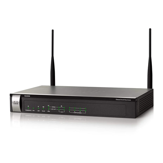
• Back Panel, page 17 Front Panel ISA550 Front Panel ISA550 Cisco Small Business SPEED LINK /ACT POWER/SYS CONFIGURABLE ISA550W Front Panel ISA550W Cisco Small Business SPEED LINK /ACT POWER/SYS WLAN CONFIGURABLE Cisco ISA500 Series Integrated Security Appliance Administration Guide... - Page 21 Green lights when the Site-to-Site VPN tunnel is established. • Green flashes when attempting to establish the Site-to- Site VPN tunnel. • Amber flashes when the system is experiencing problems setting up the Site-to-Site VPN connection. Cisco ISA500 Series Integrated Security Appliance Administration Guide...
- Page 22 Green lights when the link is up. • Green flashes when the port is transmitting and receiving data. The front panel of the ISA550 and ISA570 does not include the WLAN light. NOTE Cisco ISA500 Series Integrated Security Appliance Administration Guide...
-
Page 23: Back Panel
Ports ISA570 and ISA570W Back Panel Power Switch Reset ANT01 Button ANT02 12VDC A NT01 A NT02 CONFIGURABLE L A N RESET POWER WA N Power Connector Configurable Port Port Ports Ports Cisco ISA500 Series Integrated Security Appliance Administration Guide... -
Page 24: Installation
The back panel of ISA550 and ISA570 does not include two threaded connectors NOTE for the antennas. Installation This section describes how to install the security appliance. It includes the following topics: • Before You Begin, page 19 Cisco ISA500 Series Integrated Security Appliance Administration Guide... -
Page 25: Before You Begin
Ambient Temperature: To prevent the security appliance from overheating, do not operate it in an area that exceeds an ambient temperature of 104°F (40°C). • Air Flow: Be sure that there is adequate air flow around the device. Cisco ISA500 Series Integrated Security Appliance Administration Guide... -
Page 26: Wall Mounting
1 8mm/0.32 in 2 25mm/0.98 in 3 6.5mm/0.26in 4 18.6mm/0.73in Insecure mounting might damage the device or cause injury. Cisco is not WARNING responsible for damages incurred by improper wall-mounting. To mount the security appliance to the wall: Determine where you want to mount the security appliance. Verify that the surface STEP 1 is smooth, flat, dry, and sturdy. -
Page 27: Rack Mounting
Install the security appliance into a standard rack as shown below. Place the STEP 2 washers on the brackets so that the holes align to the screw holes and then install the M5 screws. Step 2 Step 1 Cisco ISA500 Series Integrated Security Appliance Administration Guide... -
Page 28: Hardware Installation
For a DSL or cable modem, or other WAN connectivity devices, connect an STEP 3 Ethernet network cable from the device to the WAN port on the back panel. Cisco strongly recommends using Cat5E or better cable. For network devices, connect an Ethernet network cable from the network device STEP 4 to one of the dedicated LAN ports on the back panel. -
Page 29: Getting Started With The Configuration Utility
For the first login, you are forced to immediately change the default user name and password of the default administrator account to prevent unauthorized access. For more information, see Changing the User Name and Password of the Default Administrator Account at Your First Login, page Cisco ISA500 Series Integrated Security Appliance Administration Guide... -
Page 30: Navigating Through The Configuration Utility
Click on the title of a feature or subfeature to open it. Content Pane The content of the feature or subfeature appears in this area. Cisco ISA500 Series Integrated Security Appliance Administration Guide... -
Page 31: Using The Help System
You can use the Configuration Utility to customize all settings, as needed. Settings of particular interest are described below. For a full list of all factory default settings, see Appendix C, "Factory Default Settings." Cisco ISA500 Series Integrated Security Appliance Administration Guide... - Page 32 Changing the User Name and Password of the Default Administrator Account at Your First Login, page 27. You also may want to change the user login settings for authentication. See Configuring the User Authentication Settings, page 277. Cisco ISA500 Series Integrated Security Appliance Administration Guide...
-
Page 33: Performing Common Configuration Tasks
VPN: By default, the VPN feature is disabled. The security appliance can function as a Cisco IPSec VPN server or a Cisco VPN hardware client, or as a SSL VPN gateway so that remote users can securely access the corporate network resources over the VPN tunnels. -
Page 34: Saving Your Configuration
Do not repeat any character more than three times consecutively. Do not set the password as the user name or the reversed user name. The password cannot be set as “cisco”, “ocsic”, or any variant obtained by changing the capitalization of letters. •... -
Page 35: Upgrading The Firmware If Needed
Interrupting the upgrade process at specific points when the flash is being written to can corrupt the flash memory and render the security appliance unusable. Click Device Management -> Firmware and Configuration -> Firmware. STEP 1 The Firmware window opens. Cisco ISA500 Series Integrated Security Appliance Administration Guide... -
Page 36: Resetting The Device
The Revert To Factory Default Settings operation will wipe out the current CAUTION configurations used on your security appliance (including the imported certificates). We recommmend that you save the current settings before reverting to the factory default settings. Cisco ISA500 Series Integrated Security Appliance Administration Guide... - Page 37 Click Device Management -> Firmware and Configuration -> Configuration. STEP 1 The Configuration window opens. In the Backup/Restore Settings -> Revert To Factory Default Settings area, STEP 2 click Default. The security appliance will reboot with the factory default settings. Cisco ISA500 Series Integrated Security Appliance Administration Guide...
-
Page 38: Chapter 2: Wizards
DMZ, and WLAN (for ISA550W and ISA570W only) settings. The first time you log into your security appliance, the Startup Wizard automatically launches. Click Wizard -> Startup Wizard. STEP 1 The Getting Started window opens. A prompt warning message is displayed as below. Cisco ISA500 Series Integrated Security Appliance Administrator Guide... - Page 39 Configuration Utility. Restrict a specific IP address: Only the specified remote host can access the Configuration Utility. Enter the IP address of the remote host in the IP Address field. Cisco ISA500 Series Integrated Security Appliance Administrator Guide...
- Page 40 1 WAN, 1 DMZ, and 5 LAN Switch: The security appliance is set to one WAN port (WAN1), one DMZ port, and five LAN ports. The configurable port GE7 is set to a DMZ port. Cisco ISA500 Series Integrated Security Appliance Administrator Guide...
- Page 41 7. After you are finished, click Next. STEP 5 The Secondary WAN Connection window opens. From this page you can configure the secondary WAN port. Cisco ISA500 Series Integrated Security Appliance Administrator Guide...
- Page 42 The default is 5 seconds. After you are finished, click Next. STEP 7 The LAN Configuration window opens. From this page you can configure the default LAN settings. Cisco ISA500 Series Integrated Security Appliance Administrator Guide...
- Page 43 Default Gateway: Enter the IP address of default gateway. After you are finished, click Next. STEP 8 If you have no DMZ port, skip the next two steps and proceed to the step 10. Cisco ISA500 Series Integrated Security Appliance Administrator Guide...
- Page 44 WINS 2: Optionally, enter the IP address of the secondary WINS server. • Domain Name: Optionally, enter the domain name for the DMZ. • Default Gateway: Enter the IP address of default gateway. Cisco ISA500 Series Integrated Security Appliance Administrator Guide...
- Page 45 2.4 GHz frequency to connect to the access point. 802.11b/g/n mixed: Choose this mode to allow 802.11b, 802.11g, and 802.11n clients operating in the 2.4 GHz frequency to connect to the access point. Cisco ISA500 Series Integrated Security Appliance Administrator Guide...
-
Page 46: Using The Wireless Wizard To Configure The Wireless Settings For Isa550W And Isa570W
Use the Wireless Wizard to configure the wireless radio and Intranet connectivity settings for the ISA550W and ISA570W. It includes the following sections: • Using the Wireless Wizard to Configure the Wireless Settings, page 41 Cisco ISA500 Series Integrated Security Appliance Administrator Guide... -
Page 47: Using The Wireless Wizard To Configure The Wireless Settings
After you are finished, click Next. STEP 3 The Choose SSIDs window opens. From this page you can enable the SSIDs and choose the wireless connectivity type for each active SSID. Cisco ISA500 Series Integrated Security Appliance Administrator Guide... - Page 48 The Summary window opens. The Summary page displays the summary information for all configurations you made for the SSIDs. Click Submit to save your settings and exit the Wireless Wizard. STEP 6 Cisco ISA500 Series Integrated Security Appliance Administrator Guide...
-
Page 49: Configuring The Ssid For Intranet Wlan Access
The default is 3600 seconds. For complete details for other security modes, see Configuring the NOTE Security Mode, page 162. In the Advanced Settings area, enter the following information: STEP 4 Cisco ISA500 Series Integrated Security Appliance Administrator Guide... -
Page 50: Configuring The Ssid For Guest Wlan Access
SSID will be directed to the selected VLAN. For Guest VLAN access, you should choose a VLAN that is mapped to a guest zone. Cisco ISA500 Series Integrated Security Appliance Administrator Guide... -
Page 51: Configuring The Ssid For Guest Wlan Access (Captive Portal)
In the Captive Portal WLAN Access -> Captive Portal Authentication Type area, STEP 5 specify the web authentication type and configure the relevant settings: • Web Authentication Type: Choose one of the following methods: Cisco ISA500 Series Integrated Security Appliance Administrator Guide... -
Page 52: Using The Dmz Wizard To Configure The Dmz Settings
It includes the following sections: • Using the DMZ Wizard to Configure the DMZ Settings, page 47 • Configuring the DMZ, page 48 • Configuring the DMZ Services, page 49 Cisco ISA500 Series Integrated Security Appliance Administrator Guide... -
Page 53: Using The Dmz Wizard To Configure The Dmz Settings
DMZ. After you are finished, click Next. STEP 5 The Summary window opens. The Summary window displays the summary information for all configurations you made. Cisco ISA500 Series Integrated Security Appliance Administrator Guide... -
Page 54: Configuring The Dmz
DHCP Relay, enter the IP address of the remote DHCP server in the Relay IP field. If you choose DHCP Server as the DHCP mode, enter the following information: STEP 4 • Start IP: Enter the starting IP address of the DHCP pool. Cisco ISA500 Series Integrated Security Appliance Administrator Guide... -
Page 55: Configuring The Dmz Services
Click Add to create a DMZ service. STEP 1 Other Options: To edit an entry, click Edit. To delete an entry, click Delete. To delete multiple entries, check the boxes of multiple entries and click Delete Selection. Cisco ISA500 Series Integrated Security Appliance Administrator Guide... - Page 56 Enable DMZ Service: Click On to enable the DMZ service, or click Off to create only the DMZ service. • Description: Enter the name for the DMZ service. Click OK to save your settings. STEP 3 Cisco ISA500 Series Integrated Security Appliance Administrator Guide...
-
Page 57: Using The Dual Wan Wizard To Configure The Wan Redundancy Settings
Configuring the Network Addressing Mode, page 106. After you are finished, click Next. STEP 5 The WAN Redundancy Configuration window opens. From this page you can determine how the two ISP links are used. Cisco ISA500 Series Integrated Security Appliance Administrator Guide... - Page 58 • DNS Detection-DNS Lookup using WAN DNS Servers: If you choose this option, the security appliance sends out the DNS query for www.cisco.com to the default WAN DNS server. If the DNS server can be detected, the network connection is active.
-
Page 59: Using The Site-To-Site Wizard To Establish The Site-To-Site Vpn Tunnels
• Profile Name: Enter the name for the IPSec VPN policy profile. • The Interface for this VPN: Choose the WAN interface that the traffic passes through over the IPSec VPN tunnel. Cisco ISA500 Series Integrated Security Appliance Administrator Guide... - Page 60 IPSec VPN policy profile. You can choose the default or a custom transform policy. For complete detals, see Configuring the Transform Policies, page After you are finished, click Next. STEP 5 The Local and Remote VPN Networks window opens. Enter the following information: Cisco ISA500 Series Integrated Security Appliance Administrator Guide...
-
Page 61: Configuring The Ike Policies
Name: Enter an unique name for the IKE policy. • Encryption: Choose the algorithm used to negotiate the security association. There are four algorithms supported by the security appliance: ESP_3DES, ESP_AES-128, ESP_AES-192, and ESP_AES-256. Cisco ISA500 Series Integrated Security Appliance Administrator Guide... - Page 62 The default is 24 hours. As a general rule, a shorter lifetime provides more secure ISAKMP negotiations. However, with shorter lifetimes, the security appliance sets up future IPsec SAs more quickly. Click OK to save your settings. STEP 3 Cisco ISA500 Series Integrated Security Appliance Administrator Guide...
-
Page 63: Configuring The Transform Policies
Advanced Encryption Standard supports key lengths of 128, 192, 256 bits. ESP_3DES: Encryption with 3DES (168-bit). ESP_AES_128: Encryption with AES (128-bit). ESP_AES_192: Encryption with AES (192-bit). ESP_AES_256: Encryption with AES (256-bit). Click OK to save your settings. STEP 3 Cisco ISA500 Series Integrated Security Appliance Administrator Guide... -
Page 64: Using The Remote Access Wizard To Establish The Ipsec Vpn Tunnels Or Ssl Vpn Tunnels For Remote Access
Tunnels or SSL VPN Tunnels for Remote Access The Remote Access Wizard helps you configure your security appliance as a Cisco IPSec VPN server or as a SSL VPN gateway so that remote users can securely access the corporate network resources over the VPN tunnels. It includes the following sections: •... - Page 65 Using the Remote Access Wizard to Establish the IPSec VPN Tunnels or SSL VPN Tunnels for Remote Access Figure 1 IPSec Remote Access with a Cisco VPN Client Software or a Cisco Device as a Cisco VPN Hardware Client DNS Server 10.10.10.163...
- Page 66 Cisco VPN hardware client is accessible from the corporate network over the tunnel. Specifying a operation mode is mandatory before making a connection because the Cisco VPN hardware client does not have a default mode. For more information, see Modes of Operation, page 240.
- Page 67 Access • NEM: Choose this mode for the group policy that is only used for the Cisco device that supports the Cisco VPN hardware client. The Cisco VPN hardware client will obtain a private IP address from a DHCP server over the IPSec VPN tunnel.
- Page 68 The Cisco IPSec VPN - User Group Setting window opens. From this page you can configure the user groups and enable the Cisco IPSec VPN service for them. The users in the specified user group can use the Cisco IPSec VPN group policies to establish the IPSec VPN tunnels. For complete details, see...
-
Page 69: Configuring The Cisco Ipsec Vpn User Groups
Using the Remote Access Wizard to Establish the IPSec VPN Tunnels or SSL VPN Tunnels for Remote Access Configuring the Cisco IPSec VPN User Groups In the Cisco IPSec VPN - User Group Setting window, follow these procedures to create a Cisco IPSec VPN user group. Click Add to add a Cisco IPSec VPN user group. - Page 70 Client Domain: Enter the domain name used for the SSL VPN clients. • Login Banner: After the user successfully logs into the SSL VPN server, a configurable login banner is displayed. Enter the message text to display along with the banner. Cisco ISA500 Series Integrated Security Appliance Administrator Guide...
- Page 71 SSL VPN group policy to establish the SSL VPN tunnels. For complete details, see Configuring the SSL VPN User Groups, page After you are finished, click Next. STEP 8 Cisco ISA500 Series Integrated Security Appliance Administrator Guide...
-
Page 72: Configuring The Ssl Vpn Group Policies
None: Allows the browser to use no proxy settings. Auto: Allows the browser to automatically detect proxy settings. Bypass-local: Allows the browser to bypass proxy settings that are configured on the remote user. Cisco ISA500 Series Integrated Security Appliance Administrator Guide... - Page 73 To add a destination subnet, enter the destination subnet to which a route is excluded on the SSL VPN client in the Address field and the the subnet mask for the excluded destination in the Netmask field, and then click Add. Cisco ISA500 Series Integrated Security Appliance Administrator Guide...
- Page 74 To use Split DNS, you must also have Split Tunnel mode configured. To add a domain to the Cisco AnyConnect VPN Client for tunneling packets to destinations in the private network, end the domian name in the field and then click Add.
-
Page 75: Configuring The Ssl Vpn User Groups
To create a new member, enter the user name in the User Name field and the password in the Password field, enter the password again in the Password Confirm field, and click Create. Click OK to save your settings. STEP 4 Cisco ISA500 Series Integrated Security Appliance Administrator Guide... -
Page 76: Chapter 3: Status
To access the Status pages, click Status in the left hand navigation pane. System Status The Dashboard page displays the current system status. To open this page, click Status -> Dashboard. Router Information System Name The device name of your security appliance. Cisco ISA500 Series Integrated Security Appliance Administrator Guide... - Page 77 To see complete logs, click details. Emergency Total number of Emergency logs. Click the number link for details. Alert Total number of Alert logs. Click the number link for details. Cisco ISA500 Series Integrated Security Appliance Administrator Guide...
- Page 78 Total number of active IPSec VPN sessions that initiated by your security appliance. Click the IPSec Users link for details. This option is available when your security appliance is set as the Cisco IPSec VPN Server or Cisco IPSec VPN Client. Routing Mode Display the routing mode between WAN and LAN.
- Page 79 The configurable interface that is set as the DMZ interface. Name The name of the DMZ interface. IP Address The subnet IP address of the DMZ interface. Wireless Interface To see complete details for all SSIDs, click details. Cisco ISA500 Series Integrated Security Appliance Administrator Guide...
-
Page 80: Interface Status
Indicates the station IP address, which is associated with the MAC address. MAC Address Indicates the station MAC address, which is associated with the IP address. Flag Indicates the ARP entry status. Cisco ISA500 Series Integrated Security Appliance Administrator Guide... -
Page 81: Dhcp Pool Assignment
The physical port access mode. A WAN or DMZ port is always set to Access mode and a LAN port can be set to Access or Trunk mode. VLAN The VLANs to which the physical port is mapped. Cisco ISA500 Series Integrated Security Appliance Administrator Guide... - Page 82 “Not Link”, the cable may be loose or malfunctioning. Zone The zone to which the WAN interface is assigned. VLAN Table The VLAN table displays the following VLAN information: Cisco ISA500 Series Integrated Security Appliance Administrator Guide...
-
Page 83: Interface Statistics
Link Status Shows if the port is connected or not. Tx Pxts The number of IP packets going out of the port. Rx Pxts The number of IP packets received by the port. Cisco ISA500 Series Integrated Security Appliance Administrator Guide... - Page 84 The VLAN table displays the flow statistic information for all VLANs: Name The VLAN name. Tx Pkts The number of IP packets going out of the VLAN. Rx Pkts The number of IP packets received by the VLAN. Cisco ISA500 Series Integrated Security Appliance Administrator Guide...
-
Page 85: Wireless Status For Isa550W And Isa570W
Use the Wireless pages to view the wireless status and the number of client stations that are connected to the SSIDs. It includes the following sections: • Wireless Status, page 80 • Client Status, page 81 Cisco ISA500 Series Integrated Security Appliance Administrator Guide... -
Page 86: Wireless Status
Tx B/s The number of transmitted bytes of information on the SSID. Rx B/s The number of received bytes of information on the SSID. Up Time How long the SSID has been active. Cisco ISA500 Series Integrated Security Appliance Administrator Guide... -
Page 87: Client Status
The VPN Status pages display the status and statistic information of IPSec and SSL VPN sessions. You can manually connect or disconnect the VPN tunnels. It includes the following sections: • IPSec VPN Status, page 82 • SSL VPN Status, page 83 Cisco ISA500 Series Integrated Security Appliance Administrator Guide... -
Page 88: Ipsec Vpn Status
The name of the IPSec VPN policy that is used for the VPN session. VPN Type The connection type of the IPSec VPN session, such as Site-to-Site, Cisco IPSec VPN Server, or Cisco IPSec VPN Client. WAN Interface The WAN interface used for the IPSec VPN session. -
Page 89: Ssl Vpn Status
Click this button to terminate an active SSL VPN session and hence the associated SSL VPN tunnel. Disconnect All Click this button to terminate all active SSL VPN sessions and hence the associated SSL VPN tunnels. Cisco ISA500 Series Integrated Security Appliance Administrator Guide... - Page 90 The total number of bytes in the CSTP frames received from the client. In CSTP data The number of CSTP data frames received from the client. In CSTP control The number of CSTP control frames received from the client. Cisco ISA500 Series Integrated Security Appliance Administrator Guide...
-
Page 91: Reports
CSTP is a Cisco proprietary protocol for SSL VPN tunneling. “In” means “from the NOTE client” and “Out” means “to the client”. The client is the PC running the Cisco AnyConnect VPN Client software that connects to the security appliance running the SSL VPN server. -
Page 92: Reports Of Event Logs
Web URL Filter, page 226. Click on the domain name or site name of a website to open that site in a new prompt window to see what this website is about. Cisco ISA500 Series Integrated Security Appliance Administrator Guide... -
Page 93: Reports Of Wan Bandwidth
Anti-Virus Report, page 88 • Email Security Report, page 89 • Network Reputation Report, page 90 • IPS Policy Protocol Inspection Report, page 90 • IM and P2P Blocking Report, page 91 Cisco ISA500 Series Integrated Security Appliance Administrator Guide... -
Page 94: Web Security Blocked Report
In the Anti-Virus tab, check the Enable Anti-Virus Report box to enable this report, and then click Save to save your settings. After you enable this report, the corresponding statistic information is displayed. Cisco ISA500 Series Integrated Security Appliance Administrator Guide... -
Page 95: Email Security Report
Graph Shows the total number of emails checked and the total number of spams or supposed spams detected by day for last seven days. Cisco ISA500 Series Integrated Security Appliance Administrator Guide... -
Page 96: Network Reputation Report
Inspection Report box to enable this report, and then click Save to save your settings. After you enable this report, the corresponding statistic information is displayed. Device System The current date for counting the data. Date Cisco ISA500 Series Integrated Security Appliance Administrator Guide... -
Page 97: Im And P2P Blocking Report
Total for today The total number of packets for the predefined IM and P2P applications detected and the number of packets blocked in one day. Cisco ISA500 Series Integrated Security Appliance Administrator Guide... -
Page 98: Process Status
CPU Usage by kernal The percentage of CPU resource used by kernel space processes since the security appliance boots CPU Idle The percentage of CPU idle since the security appliance boots up. Cisco ISA500 Series Integrated Security Appliance Administrator Guide... - Page 99 The amount of memory space not used by the processes at current time. Cached Memory The amount of memory space used as cache at current time. Buffer Memory The amount of memory space used as buffers at current time. Cisco ISA500 Series Integrated Security Appliance Administrator Guide...
-
Page 100: Chapter 4: Networking
VRRP, page 139 • Configuring the Quality of Service, page 140 • Address Management, page 152 • Service Management, page 154 To access the Networking pages, click Networking in the left hand navigation pane. Cisco ISA500 Series Integrated Security Appliance Administrator Guide... -
Page 101: Configuring Ip Routing Mode
Configuring 802.1X Access Control on Physical Ports, page 98 • Configuring the Port Mirroring, page 100 Viewing the Status of Physical Interfaces Click Networking -> Port -> Physical Interface. STEP 1 The Physical Interface window opens. Cisco ISA500 Series Integrated Security Appliance Administrator Guide... -
Page 102: Configuring The Physical Interfaces
You can enable or disable a physical interface, assign the physical interfaces to VLANs, and configure the duplex mode. Click Networking -> Port -> Physical Interface. STEP 1 The Physical Interface window opens. Cisco ISA500 Series Integrated Security Appliance Administrator Guide... - Page 103 To create new VLANs, click Create VLAN. For more information about NOTE how to configure the VLANs, see Configuring the VLAN, page 118. • Flow Control: Click On to control the flow on the port, or click Off to disable Cisco ISA500 Series Integrated Security Appliance Administrator Guide...
-
Page 104: Configuring 802.1X Access Control On Physical Ports
RADIUS servers to provide backups in case access to the primary server fails). It also means that user can enter the same authorized RADIUS username and password pair for authentication, regardless of which switch is the access point into the LAN. Cisco ISA500 Series Integrated Security Appliance Administrator Guide... - Page 105 • Guest Authentication: After you enable 802.1X access control, check the box in this column to enable Guest Authentication, or uncheck the box to disable it. Cisco ISA500 Series Integrated Security Appliance Administrator Guide...
-
Page 106: Configuring The Port Mirroring
Click On to enable port mirroring, or click Off to disable it. STEP 2 If you enable port mirroring, enter the following information: STEP 3 • TX Destination: Choose the port that monitors the tranmitted traffic for other ports. Cisco ISA500 Series Integrated Security Appliance Administrator Guide... -
Page 107: Configuring The Wan
STEP 2 After you click Edit, the WAN - Add/Edit window opens. In the IPv4 tab, enter the following information: STEP 3 • Physical Port: The physical port associated with the primary WAN. Cisco ISA500 Series Integrated Security Appliance Administrator Guide... - Page 108 • DNS Server Source: DNS servers map Internet domain names (example: www.cisco.com) to IP addresses. You can get DNS server addresses automatically from your ISP or use ISP-specified addresses. Get Dynamically from ISP: Choose this option if you have not been assigned a static DNS IP address.
- Page 109 WAN port, and then configure the WAN redundancy settings. Configuring the WAN Redundancy, page 112. • If you are having problems with your WAN connection, see the Internet Connection, page 333 Troubleshooting, page 333. Cisco ISA500 Series Integrated Security Appliance Administrator Guide...
-
Page 110: Configuring The Secondary Wan
• DNS Server Source: DNS servers map Internet domain names (example: www.cisco.com) to IP addresses. You can get DNS server addresses automatically from your ISP or use ISP-specified addresses. Get Dynamically from ISP: Choose this option if you have not been assigned a static DNS IP address. - Page 111 Primary DNS Server: Enter a valid IP address of the primary DNS Server. Secondary DNS Server (Optional): Optionally, enter a valid IP address of the secondary DNS Server. Click OK to save your settings. STEP 5 Click Save to apply your settings. STEP 6 Cisco ISA500 Series Integrated Security Appliance Administrator Guide...
-
Page 112: Configuring The Network Addressing Mode
MTU Value: If you choose Manual, enter the custom MTU size in bytes. NOTE Unless a change is required by your ISP, it is recommended that the MTU values be left as is. Cisco ISA500 Series Integrated Security Appliance Administrator Guide... - Page 113 MTU Value: If you choose Manual, enter the custom MTU size in bytes. NOTE Unless a change is required by your ISP, it is recommended that the MTU values be left as is. Cisco ISA500 Series Integrated Security Appliance Administrator Guide...
- Page 114 MTU Value: If you choose Manual, enter the custom MTU size in bytes. NOTE Unless a change is required by your ISP, it is recommended that the MTU values be left as is. Cisco ISA500 Series Integrated Security Appliance Administrator Guide...
- Page 115 MTU Value: If you choose Manual, enter the custom MTU size in bytes. NOTE Unless a change is required by your ISP, it is recommended that the MTU values be left as is. Cisco ISA500 Series Integrated Security Appliance Administrator Guide...
- Page 116 MTU Value: If you choose Manual, enter the custom MTU size in bytes. NOTE Unless a change is required by your ISP, it is recommended that the MTU values be left as is. Cisco ISA500 Series Integrated Security Appliance Administrator Guide...
-
Page 117: Configuring The Pppoe Profiles
(such as the client user's password). MS-CHAP: MS-CHAP is the Microsoft version of the CHAP. The protocol exists in two versions, MS-CHAPv1 (defined in RFC 2433) and MS- CHAPv2 (defined in RFC 2759). Cisco ISA500 Series Integrated Security Appliance Administrator Guide... -
Page 118: Configuring The Wan Redundancy
WAN redundancy to determine how the two ISP links are used. Before you configure the WAN redundancy, you must configure the secondary NOTE WAN connection. See Configuring the Secondary WAN, page 104. Cisco ISA500 Series Integrated Security Appliance Administrator Guide... -
Page 119: Loading Balancing For Wan Redundancy
Dual WAN configured with the Load Balancing. Figure 2 Example of Dual WAN Ports with Load Balancing Dual WAN Ports (Load Balancing) WAN1 IP ISA500 yourcompany1.dyndns.org Internet yourcompany2.dyndns.org WAN2 IP Cisco ISA500 Series Integrated Security Appliance Administrator Guide... - Page 120 Policy Based Routing Enable: Click On to enable the PBR settings, or click Off to disable it. To configure the PBR settings, click Configure PBR. If you enable PBR, the PBR settings will be applied first and then the NOTE load balancing settings next. Cisco ISA500 Series Integrated Security Appliance Administrator Guide...
-
Page 121: Load Balancing With Policy-Based Routing Configuration Example
Configuring Policy-based Routing Settings, page 134. • Enable the IP Bandwidth, Service Bandwidth, and WAN Bandwidth reports so that you can check the WAN bandwidth usage by IP address, service, and time. See Reports, page Cisco ISA500 Series Integrated Security Appliance Administrator Guide... -
Page 122: Failover For Wan Redundancy
Preempt Delay Timer: Enter the time in seconds that the system will preempt the primary link from the backup link when the primary link is up again. The default is 5 seconds. Click Save to apply your settings. STEP 3 Cisco ISA500 Series Integrated Security Appliance Administrator Guide... -
Page 123: Routing Table For Wan Redundancy
STEP 1 The Link Failover Detection Settings window opens. Enter the following information: STEP 2 • Failover Detection: Click On to enable the Link Failover Detection feature, or click Off to disable it. Cisco ISA500 Series Integrated Security Appliance Administrator Guide... -
Page 124: Configuring The Vlan
DNS servers that you specify in the following fields: DNS Lookup using WAN DNS Servers: The security appliance sends the DNS query for www.cisco.com to the default WAN DNS server. If the DNS server can be detected, the network connection is active. -
Page 125: Configuring The Vlans
Port: Assigns the LAN ports to the VLAN. The traffic through the selected LAN ports is directed to the VLAN. All available ports including the dedicated LAN ports and configurable ports appear in the Port list. Cisco ISA500 Series Integrated Security Appliance Administrator Guide... - Page 126 End IP: Enter the last IP address in the DHCP range. Any new DHCP client joining the VLAN is assigned an IP address between the Start IP address and End IP address. Cisco ISA500 Series Integrated Security Appliance Administrator Guide...
- Page 127 Cisco CallManager and other servers at branch offices. Cisco IP Phones download their configuration from a TFTP server. When a Cisco IP Phone starts, if it does not have both the IP address and TFTP server IP address pre-configured, it sends a request with option 150 or 66 to the DHCP server to obtain this information.
-
Page 128: Configuring Dhcp Reserved Ips
IP Address: Enter the IP address within the VLAN’s DHCP pool that is assigned to the host. Click OK to save your settings. STEP 4 Click Save to apply your settings. STEP 5 Cisco ISA500 Series Integrated Security Appliance Administrator Guide... -
Page 129: Configuring The Dmz
Internet Source Address Translation Public IP Address 209.165.200.225 172.16.2.30 209.165.200.225 DMZ Interface 172.16.2.1 ISA500 LAN Interface Web Server Private IP Address: 172.16.2.30 192.168.75.1 Public IP Address: 209.165.200.225 User User 192.168.75.10 192.168.75.11 Cisco ISA500 Series Integrated Security Appliance Administrator Guide... - Page 130 209.165.200.226. The address 209.165.200.225 is used for the security appliance’s public IP address. The administrator configures the configurable port to be used as a DMZ port and created a firewall access rule to allow inbound Cisco ISA500 Series Integrated Security Appliance Administrator Guide...
- Page 131 Up to five DMZ interfaces can be configured for ISA570 and NOTE ISA570W. Up to four DMZ interfaces can be configured for ISA550 and ISA550W. • Zone: Choose the default or custom DMZ zone to which the DMZ is mapped. Cisco ISA500 Series Integrated Security Appliance Administrator Guide...
- Page 132 In the IPv6 Setting tab, specify the IPv6 addressing for the DMZ if you enable the STEP 6 IPv4/IPv6 mode. • IPv6 Address: Enter the IPv6 address based on your network requirements. • IPv6 Prefix Length: Enter the number of characters in the IPv6 prefix. Cisco ISA500 Series Integrated Security Appliance Administrator Guide...
-
Page 133: Configuring The Zones
This section describes the security level definition for zones, the predefined zones, and how to create new zones. It includes the following topics: • Security Levels for Zones, page 128 • Predefined Zones, page 128 • Configuring the Zones, page 129 Cisco ISA500 Series Integrated Security Appliance Administrator Guide... -
Page 134: Security Levels For Zones
LAN: The LAN zone is a trusted zone. You can map one or multiple VLANs to a trusted zone. By default, the DEFAULT VLAN is mapped to the LAN zone. • DMZ: The DMZ zone is a public zone used for accessible servers. Cisco ISA500 Series Integrated Security Appliance Administrator Guide... -
Page 135: Configuring The Zones
VOICE: The VOICE zone is a security zone designed for voice traffic. Traffic coming and outgoing from this zone will be optimized for voice operations. If you have voice devices, such as a Cisco IP Phone, it is desirable to place the devices into the VOICE zone. -
Page 136: Configuring The Routing
Use the Routing pages to change the routing mode between WAN and LAN, view the routing table, configure the static routing, dynamic routing, and Policy-based Routing settings. It includes the following sections: • Configuring the Routing Mode, page 131 Cisco ISA500 Series Integrated Security Appliance Administrator Guide... -
Page 137: Configuring The Routing Mode
Destination Address: The IP address of the host or the network that the route leads to. • Netmask: The subnet mask of the destination network. • Gateway: The IP address of the gateway through which the destination host or network can be reached. Cisco ISA500 Series Integrated Security Appliance Administrator Guide... -
Page 138: Configuring The Static Routing
Setting as Default Route: Check this box to set this static route as the default route. • Next Hop: Choose an interface or an IP address as the next hop for this static route. Interface: Choose either WAN1 or WAN2 as the next hop. Cisco ISA500 Series Integrated Security Appliance Administrator Guide... -
Page 139: Configuring The Dynamic Routing
This is the default setting. Specify the RIP setting for each available interface: STEP 3 • RIP Enable: Check this box to enable the RIP settings on the interface or VLAN. Cisco ISA500 Series Integrated Security Appliance Administrator Guide... -
Page 140: Configuring Policy-Based Routing Settings
Load Balancing or Routing Table mode before you configure the policy-based routing settings. See Configuring the Secondary WAN, page 104 Configuring the WAN Redundancy, page 112. The security appliance supports up to 100 PBR rules. NOTE Cisco ISA500 Series Integrated Security Appliance Administrator Guide... - Page 141 If one WAN connection is down (a connection failure is detected by NOTE ping the host or DNS server) and the PBR Failover is “Off”, the traffic will be dropped. Click OK to save your settings. STEP 5 Cisco ISA500 Series Integrated Security Appliance Administrator Guide...
-
Page 142: Priority Of Routing Rules
Other options: To edit an entry, click Edit. To delete an entry, click Delete. After you click Add or Edit, the Edit window opens. Enter the following information: STEP 3 • Service: Choose either DynDNS or No-IP service. Cisco ISA500 Series Integrated Security Appliance Administrator Guide... - Page 143 NOT complete yet. Active(updated WAN ): Indicates that the DDNS updating process is complete and the address of WANx is updated to the user-specified domain name. Click OK to save your settings. STEP 4 Cisco ISA500 Series Integrated Security Appliance Administrator Guide...
-
Page 144: Igmp
IGMP Version: Choose either IGMPv1&v2 or IGMPv3. IGMPv1: Hosts can join multicast groups. There are no leave messages. Routers use a time-out based mechanism to discover the groups that are of no interest to the members. Cisco ISA500 Series Integrated Security Appliance Administrator Guide... -
Page 145: Vrrp
Source IP: The source IP address of the master virtual router. If a VRRP router owns the IP address of the virtual router and the IP NOTE address of the physical interface, this router will function as a master virtual router . Cisco ISA500 Series Integrated Security Appliance Administrator Guide... -
Page 146: Configuring The Quality Of Service
Configuring the Quality of Service The Quality of Service (QoS) feature is applied throughout the network to ensure that network traffic is prioritized according to required criteria and that the desired traffic receives preferential treatment. Cisco ISA500 Series Integrated Security Appliance Administrator Guide... -
Page 147: General Qos Settings
Click Save to apply your settings. STEP 3 Configuring the WAN QoS This section describes how to configure the WAN QoS settings. It includes the following topics: • Managing the WAN Bandwidth for Upstream Traffic, page 142 Cisco ISA500 Series Integrated Security Appliance Administrator Guide... -
Page 148: Managing The Wan Bandwidth For Upstream Traffic
The security appliance supports six queues for WAN ports, Q1 to Q6. There are three ways of determining how traffic in queues is handled: Strict Priority (SP), Weighted Round Robin (WRR), and Low Latency Queueing (LLQ). Cisco ISA500 Series Integrated Security Appliance Administrator Guide... - Page 149 Assuming the packet source is using TCP, it will decrease its transmission rate until all the packets reach their destination, indicating that the congestion is cleared. Cisco ISA500 Series Integrated Security Appliance Administrator Guide...
-
Page 150: Configuring The Traffic Selectors For Wan Interfaces
Address to create a new address object. To maintain the address or group address objects, go to the Networking -> Address Object Management page. See Address Management, page 152. • Source Service: Choose Any or choose an existing service from the drop- down list. Cisco ISA500 Series Integrated Security Appliance Administrator Guide... -
Page 151: Configuring The Wan Qos Policy Profiles
Other options: To edit an entry, click Edit. To delete an entry, click Delete. After you click Add or Edit, the QoS Policy Profile - Add/Edit window opens. Enter the following information: STEP 3 Cisco ISA500 Series Integrated Security Appliance Administrator Guide... -
Page 152: Mapping The Wan Qos Policy Profiles To Wan Interfaces
The Policy Profile to Interfaces Mapping window opens. To edit the policy profile settings associated with a WAN interface, click Edit. STEP 2 After you click Edit, the Policy Profile to Interfaces Mapping - Edit window opens. Cisco ISA500 Series Integrated Security Appliance Administrator Guide... -
Page 153: Configuring The Lan Qos
STEP 1 The Queue Settings window opens. If needed, enter the description for each queue in the Queue Description column. STEP 2 Specify how to determine the traffic in queues. STEP 3 Cisco ISA500 Series Integrated Security Appliance Administrator Guide... -
Page 154: Configuring The Lan Qos Classification Methods
Traffic Classification is used to classify the traffic through the LAN interfaces to a given traffic class so that the traffic in need of management can be identified. Click Networking -> QoS -> LAN QoS -> Classification Method. STEP 1 The Classification Method window opens. Cisco ISA500 Series Integrated Security Appliance Administrator Guide... -
Page 155: Mapping Cos To Lan Queue
LAN interface. The possible field values are 0 to 7. The default CoS value is 0. Click Networking -> QoS -> LAN QoS -> Default CoS. STEP 1 The Default CoS window opens. Enter the following information: STEP 2 Cisco ISA500 Series Integrated Security Appliance Administrator Guide... -
Page 156: Configuring The Wireless Qos
CoS or DSCP and wireless queues are editable. 802.1p DSCP Wireless Queue WMM value 000xxx Q3 (Best Effort Priority) 001xxx Q4 (Background Priority) 010xxx Q4 (Background Priority) 011xxx Q3 (Best Effort Priority) Cisco ISA500 Series Integrated Security Appliance Administrator Guide... -
Page 157: Configuring The Wireless Qos Classification Methods
Click Save to apply your settings. STEP 3 Mapping DSCP to Wireless Queue Click Networking -> QoS -> Wireless QoS -> Mapping DSCP to Queue. STEP 1 The Mapping DSCP to Queue window opens. Cisco ISA500 Series Integrated Security Appliance Administrator Guide... -
Page 158: Address Management
After you click Add or Edit, the Address Table - Add/Edit window opens. Enter the following informaiton: STEP 3 • Name: Enter the name for the address object. • Type: Specify the address type and then enter the corresponding information. Cisco ISA500 Series Integrated Security Appliance Administrator Guide... -
Page 159: Configuring The Group Addresses
The Address Object Management window opens. All existing group address objects are listed in the Group Address table. In the Group Address Table area, click Add Group to add a new group address. STEP 2 Cisco ISA500 Series Integrated Security Appliance Administrator Guide... -
Page 160: Service Management
Click Network -> Services. STEP 1 The Services window opens. All existing service objects are listed in the Service table. In the Service Table area, click Add to add a new service. STEP 2 Cisco ISA500 Series Integrated Security Appliance Administrator Guide... -
Page 161: Configuring The Group Services
Services that apply to common applications are grouped as a group service object. The group service object is treated as a single service. A group service can include up to 64 service members. The security appliance can support up to 64 group services. Cisco ISA500 Series Integrated Security Appliance Administrator Guide... - Page 162 To remove the services from the group, select the services from the Member list STEP 5 and click the left arrow <-. Click OK to save your settings. STEP 6 Click Save to apply your settings. STEP 7 Cisco ISA500 Series Integrated Security Appliance Administrator Guide...
-
Page 163: Chapter 5: Wireless Configuration For Isa550W And Isa570W
IEEE 802.11b, 802.11g, and 802.11n. This section describes how to configure the wireless radio settings. It includes the following topics: • Basic Radio Settings, page 158 • Advanced Radio Settings, page 160 Cisco ISA500 Series Integrated Security Appliance Administrator Guide... -
Page 164: Basic Radio Settings
802.11n clients operating in the 2.4 GHz frequency to connect to the access point. • Wireless Channel: Choose a channel or choose Auto to let the system determine the optical channel to use based on the environmental noise levels for the available channels. Cisco ISA500 Series Integrated Security Appliance Administrator Guide... - Page 165 WMM: Check this box to enable the Wi-Fi Multimedia (WMM) QoS feature for the SSID. WMM refers to QoS over Wi-Fi. QoS enables Wi-Fi SSIDs to prioritize traffic and optimizes the way shared network resources are allocated among different applications. Cisco ISA500 Series Integrated Security Appliance Administrator Guide...
-
Page 166: Advanced Radio Settings
Power Output: You can adjust the output power of the access point to get the appropriate coverage for your wireless network. Choose the level you need for your environment. If you are not sure of which setting to select, then keep the default setting, 100%. Cisco ISA500 Series Integrated Security Appliance Administrator Guide... - Page 167 Set the threshold by entering the frame length in bytes. Enter a value from 256 to 2346. The default value is 2346, which effectively disables fragmentation. Click Save to apply your settings. STEP 3 Cisco ISA500 Series Integrated Security Appliance Administrator Guide...
-
Page 168: Configuring The Access Points
Configuring the SSID Schedule, page 171 Configuring the Security Mode This section describes how to configure the security mode for the SSID. Cisco strongly recommends WPA2 for wireless security. Other security modes are NOTE vulnerable to attacks. If the security mode is set as WEP or as WPA with TKIP encryption algorithm for the NOTE SSID that supports 802.11n, the transmit rate for its associated client stations will... - Page 169 WEP encryption is an older encryption method that is not considered to be secure and can easily be broken. Select this option only if you need to allow access to devices that do not support WPA or WPA2. Cisco ISA500 Series Integrated Security Appliance Administrator Guide...
- Page 170 WPA2-Enterprise: WPA2-Enterprise uses an external RADIUS server for client authentication. WPA2-Enterprise always uses AES encryption mechanism for data encryption. This security mode is only available when a RADIUS server is connected to the SSID. Cisco ISA500 Series Integrated Security Appliance Administrator Guide...
- Page 171 Auto to let the security appliance accept both Open System and Shared Key schemes. • Default Transmit Key: Choose a key index as the default transmit key. Key indexes 1 through 4 are available. Cisco ISA500 Series Integrated Security Appliance Administrator Guide...
- Page 172 A value of 0 indicates that the key is not refreshed. The default is 3600 seconds. If you choose WPA/WPA2-Personal Mixed as the security mode, enter the STEP 8 following information: • Encryption: WPA/WPA2-Personal Mixed automtically choose TKIP or AES for data encryption. Cisco ISA500 Series Integrated Security Appliance Administrator Guide...
- Page 173 Secondary RADIUS Server IP Address: The IP address for the secondary RADIUS server. Secondary RADIUS Server Port: The port number for the secondary RADIUS server. Secondary RADIUS Server Shared Secret: The shared secret key for the secondary RADIUS server. Cisco ISA500 Series Integrated Security Appliance Administrator Guide...
- Page 174 Go to the Device Management -> RADIUS Settings page to maintain the RADIUS server settings. See Configuring the RADIUS Servers, page 319. Cisco ISA500 Series Integrated Security Appliance Administrator Guide...
-
Page 175: Controlling The Wireless Access Based On Mac Addresses
• Connection Control: Check the Enable box to enable the MAC Filtering feature for the SSID. If you enabled this feature, choose one of the following options as the MAC filtering policy: Cisco ISA500 Series Integrated Security Appliance Administrator Guide... -
Page 176: Mapping The Ssid To Vlan
VLAN. All traffic from the wireless clients that are connected to this SSID will be directed to the selected VLAN. Click OK to save your settings. STEP 4 Click Save to apply your settings. STEP 5 Cisco ISA500 Series Integrated Security Appliance Administrator Guide... -
Page 177: Configuring The Ssid Schedule
Stop Time: Enter the values in the hour and minute fields, and choose AM or PM from the drop-down list. Click OK to save your settings. STEP 4 Click Save to apply your settings. STEP 5 Cisco ISA500 Series Integrated Security Appliance Administrator Guide... -
Page 178: Configuring Wi-Fi Protected Setup
Check the following WPS status: STEP 6 • WPS Config Status: If you enable WPS, it shows as “Configured”. • Network Name (SSID): Choose the SSID on which the WPS setting is applied. Cisco ISA500 Series Integrated Security Appliance Administrator Guide... -
Page 179: Configuring Wireless Rogue Ap Detection
To set an AP as an authorized AP, click Grant Access. The granted AP is moved to STEP 4 the Known AP list. The security appliance will not detect the authorized APs. You can specify the STEP 5 authorized APs in the known AP list. Cisco ISA500 Series Integrated Security Appliance Administrator Guide... -
Page 180: Configuring Wireless Captive Portal
Enable Captive Portal: Click On to enable the captive portal feature, or click Off to disable it. • Apply On: Choose the SSID on which the captive portal settings are applied. The captive portal WLAN access can be only applied on one SSID. NOTE Cisco ISA500 Series Integrated Security Appliance Administrator Guide... - Page 181 If you choose this option, you can modify the following information on the default web authentication login page: Cisco Logo: If you want to hide the Cisco logo that appears in the top right corner of the default page, choose Hide. Otherwise, choose Show.
- Page 182 • Logo File: You can import your company logo to change the default Cisco logo that appears in the top right corner of the default page. Click Browse to locate and select the logo file from your local PC, and then click Upgrade. To delete the upgraded logo file and revert the default Cisco logo, click Delete.
-
Page 183: Chapter 6: Firewall
Configuring the IP/MAC Binding to Prevent Spoofing, page 206 • Configuring the Attack Protection, page 207 • Configuring the Application Level Gateway, page 209 To access the Firewall pages, click Firewall in the left hand navigation pane. Cisco ISA500 Series Integrated Security Appliance Administrator Guide... -
Page 184: Configuring The Firewall Access Rules To Control Inbound And Outbound Traffic
For more information about the security level definition for zones, see Security Levels for Zones, page 128. From\To Trusted(100) VPN(75) Public(50) GUEST(25) Untrust(0) Trusted(100) Deny Permit Permit Permit Permit VPN(75) Deny Deny Permit Permit Permit Cisco ISA500 Series Integrated Security Appliance Administrator Guide... - Page 185 Deny Deny Deny Permit Permit Permit SSLVPN Deny Deny Deny Permit Permit Permit Deny Deny Deny Deny Permit Permit GUEST Deny Deny Deny Deny Deny Permit Deny Deny Deny Deny Deny Deny Cisco ISA500 Series Integrated Security Appliance Administrator Guide...
-
Page 186: Priorities Of Firewall Access Rules
Management, page 154. • To create the firewall access rule that applies only to a specific address or group address, first create the address or group address object. See Address Management, page 152. Cisco ISA500 Series Integrated Security Appliance Administrator Guide... -
Page 187: General Settings For Configuring The Firewall Access Rules
You can perform other tasks for access rules: STEP 4 • Enable: Check this box to enable an access rule, or uncheck this box to disable it. By default, all default access rules are enabled. Cisco ISA500 Series Integrated Security Appliance Administrator Guide... - Page 188 Reset Count: To set the values in the Hit Count culumn for all access rules to zero, click Reset Count. The default access rules can not be disabled, deleted, edited, and NOTE moved. Cisco ISA500 Series Integrated Security Appliance Administrator Guide...
-
Page 189: Configuring A Firewall Access Rule
New Address to create new address objects, or choose Create New Group to create new group address objects. To maintain the address and address group objects, go to the Networking -> Address Object Management page. See Address Management, page 152. Cisco ISA500 Series Integrated Security Appliance Administrator Guide... - Page 190 Configuring the IP/MAC Binding to Prevent Spoofing, page 206 • Allowing or blocking the websites that contain a specific URL or URL keyword. See Configuring the Content Filtering to Control Access to Internet, page 201. Cisco ISA500 Series Integrated Security Appliance Administrator Guide...
-
Page 191: Configuring A Firewall Access Rule To Allow The Multicast Traffic
• Schedule: Choose Always On for this rule. • Log: Click Off for this rule. We recommend that you disable the Log feature for a multicast firewall access rule. Cisco ISA500 Series Integrated Security Appliance Administrator Guide... -
Page 192: Configuring The Firewall Schedule
Scheduled Time of Day: Schedule the access rules on all days or at a specific time of day. All Days: Choose this option if you want to keep the access rule always Cisco ISA500 Series Integrated Security Appliance Administrator Guide... -
Page 193: Firewall Access Rule Configuration Examples
Go to the Firewall -> NAT -> Port Forwarding page to create a port forwarding STEP 3 rule as follows. Original Service FTP-CONTROL Translated Service FTP-CONTROL Translated IP InternalFTP WAN1 WAN IP WAN1_IP Enable Port Forwarding Cisco ISA500 Series Integrated Security Appliance Administrator Guide... - Page 194 Then go to the Firewall -> ACL Rules -> Rule page to create a firewall access rule STEP 5 as follows to allow the access: From Zone To Zone Services FTP-CONTROL Source Address Destination Address InternalFTP Match Action Permit Cisco ISA500 Series Integrated Security Appliance Administrator Guide...
- Page 195 Enable Port Forwarding Or go to the Firewall -> NAT -> Advanced NAT page to create an Advanced NAT STEP 5 rule as follows. From WAN1 Original source address Original destination PublicIP address Cisco ISA500 Series Integrated Security Appliance Administrator Guide...
- Page 196 192.168.1.110 called “InternalIP”, and then create an access rule as follows. In the example, connections for CU-SeeMe (an Internet video-conferencing client) are allowed only from a specified range of external IP addresses. Parameter Value From Zone To Zone Services CU-SEEME Cisco ISA500 Series Integrated Security Appliance Administrator Guide...
- Page 197 Solution: Create a host address object with the IP address 10.64.173.20 called “OffsiteMail”, and then configure an access rule as follows. Parameter Value From Zone To Zone Cisco ISA500 Series Integrated Security Appliance Administrator Guide...
-
Page 198: Configuring The Nat Rules To Securely Access A Remote Network
Configuring Static NAT Rules, page 194 • Configuring Port Forwarding Rules, page 195 • Configuring Port Triggering Rules, page 196 • Configuring Advanced NAT Rules, page 197 • Viewing NAT Translation Status, page 199 Cisco ISA500 Series Integrated Security Appliance Administrator Guide... -
Page 199: Configuring Dynamic Pat Rules
VLAN into the public IP address specified on the WAN2 port. • VLAN IP: The subnet IP address and netmask of the selected VLAN. Click Save to apply your settings. STEP 4 Cisco ISA500 Series Integrated Security Appliance Administrator Guide... -
Page 200: Configuring Static Nat Rules
IP address object. To maintain the IP address objects, go to the Networking -> Address Object Management page. See Address Management, page 152. Click OK to save your settings. STEP 4 Cisco ISA500 Series Integrated Security Appliance Administrator Guide... -
Page 201: Configuring Port Forwarding Rules
Enter the following information: STEP 3 • Original Service: Choose an existing service as the incoming service. • Translated Service: Choose an existing service as the translated service that you will host. Cisco ISA500 Series Integrated Security Appliance Administrator Guide... -
Page 202: Configuring Port Triggering Rules
You can specify a port triggering rule by defining the type of traffic (TCP or UDP) and the range of incoming and outgoing ports to open when enabled. Cisco ISA500 Series Integrated Security Appliance Administrator Guide... -
Page 203: Configuring Advanced Nat Rules
Click Save to apply your settings. STEP 6 Configuring Advanced NAT Rules Advanced NAT allows you to identify real addresses and real ports for address translation by specifying the source and destination addresses. Cisco ISA500 Series Integrated Security Appliance Administrator Guide... - Page 204 Translated Source Address: Choose the translated source address for the packet. • Translated Destination Address: Choose the translated destination address for the packet. • Translated Service: Choose the translated TCP or UDP service. Cisco ISA500 Series Integrated Security Appliance Administrator Guide...
-
Page 205: Viewing Nat Translation Status
Translated Source Port: The source interface that the specified source port is translated to. • Translated Destination Port: The destination interface that the specified destination port is translated to. • TxPkt: The number of transmitted packets. Cisco ISA500 Series Integrated Security Appliance Administrator Guide... -
Page 206: Priorities Of Nat Rules
1200 seconds. • UDP Timeout: Enter the timeout value in seconds for UDP session. Inactive UDP sessions are removed from the session table after this duration. The default is 180 seconds. Cisco ISA500 Series Integrated Security Appliance Administrator Guide... -
Page 207: Configuring The Content Filtering To Control Access To Internet
A Content Filtering policy profile is used to specify the websites to be blocked or permitted. The security appliance supports up to 16 content filtering policy profiles. NOTE Click Firewall -> Content Filtering -> Content Filtering Policy. STEP 1 The Content Filtering Policy window opens. Cisco ISA500 Series Integrated Security Appliance Administrator Guide... - Page 208 & Zone Mapping page. See Mapping the Content Filtering Policy Profiles to Zones, page 204. • To configure advanced content filtering settings, go to the Advanced Settings page. See Configuring Advanced Settings, page 204. Cisco ISA500 Series Integrated Security Appliance Administrator Guide...
-
Page 209: Configuring The Website Access Control List
• Action: Choose Permit to permit the access, or choose Block to block the access. Click OK to save your settings. STEP 3 Cisco ISA500 Series Integrated Security Appliance Administrator Guide... -
Page 210: Mapping The Content Filtering Policy Profiles To Zones
Java: Check the box to block applets from being downloaded from internet sites. ActiveX: Check the box to prevent ActiveX controls from being downloaded via Internet Explorer. Cisco ISA500 Series Integrated Security Appliance Administrator Guide... -
Page 211: Configuring The Mac Filtering To Permit Or Block Traffic
Specify the list of MAC addresses. To add a MAC address to the table, click Add. STEP 4 To edit an entry, click Edit. To delete an entry, click Delete. To delete all selected entries, check the boxes of multiple entries and click Delete Selection. Cisco ISA500 Series Integrated Security Appliance Administrator Guide... -
Page 212: Configuring The Ip/Mac Binding To Prevent Spoofing
Create a MAC to add a new MAC address object. To maintain the MAC address objects, go to the Networking -> Address Object Management page. See Address Management, page 152. Cisco ISA500 Series Integrated Security Appliance Administrator Guide... -
Page 213: Configuring The Attack Protection
SYN (synchronize) requests to a target system. It blocks all TCP SYN flood attackes (200 packets per seconds) from the WAN interfaces. In the LAN Security Checks section, enter the following information: STEP 3 Cisco ISA500 Series Integrated Security Appliance Administrator Guide... - Page 214 ICMP flood intrusion event is occurring. Enter a value from 0 to 10000 ICMP packets per second. A value of zero indicates that the IGMP Flood feature is disabled. Click Save to apply your settings. STEP 6 Cisco ISA500 Series Integrated Security Appliance Administrator Guide...
-
Page 215: Configuring The Application Level Gateway
Check this box to allow the H.323 sessions to pass through the security appliance, or uncheck this box to block the H.323 sessions. Click Save to apply your settings. STEP 3 Cisco ISA500 Series Integrated Security Appliance Administrator Guide... -
Page 216: Chapter 7: Security Services
About the Security Services, page 211 • Security License, page 212 • Priority of Security Services, page 212 • Managing the Security Services, page 212 • Viewing the Security Service Reports, page 214 Cisco ISA500 Series Integrated Security Appliance Administrator Guide... -
Page 217: About The Security Services
The Network Reputation service checks the source and Reputation destination address of each packet against the address blacklist to determine whether to proceed or drop the packet. For more information, see Network Reputation, page 231. Cisco ISA500 Series Integrated Security Appliance Administrator Guide... -
Page 218: Security License
In the License Status area, check the expiration date for the security license. If the STEP 2 security license expires, go to the Device Management -> License Management page to renew the license. In the Settings Summary area, you can perform the following tasks: STEP 3 Cisco ISA500 Series Integrated Security Appliance Administrator Guide... - Page 219 • For the signature-based security services, such as Anti-Virus and IPS, click Check for Updates Now to check for new signatures from the Cisco server. The date and time of the last check are displayed in the Last Check column.
-
Page 220: Viewing The Security Service Reports
Enabling IPS consumes additional system resources and may impact the system CAUTION performance. Go to the Status -> Dashboard page to view the CPU and memory utilizations. To conserve the system resources, disable the IPS service when it is no longer needed. Cisco ISA500 Series Integrated Security Appliance Administrator Guide... -
Page 221: General Ips Settings
Email Alert Setting: IPS sends an alert message to the specified email account if an attack hits the email alert threshold. Click this link to see the email alert settings for IPS Alert events. Cisco ISA500 Series Integrated Security Appliance Administrator Guide... -
Page 222: Configuring The Ips Policy And Protocol Inspection
• Manual Signature Updates: To manually update the IPS signatures, you first need to download the latest signature file from the Cisco server to your local PC. The user name and password of your registered CCO account are required to log into the Cisco server. Then click Browse to locate and select the signature file from your local PC, and click Upload. - Page 223 To save the IPS logs in the lcoal syslog daemon, you need to enable the Log feature, set the log buffer size and the severity for local log, and then check the Local Log box for the IPS (signature based) and IPS (reputation based) log facilities. Cisco ISA500 Series Integrated Security Appliance Administrator Guide...
-
Page 224: Blocking The Instant Messaging And Peer-To-Peer Applications
For example, if you choose MSN, only the signatures under the MSN application are displayed. To display all signatures, choose All. • View P2P Blocking Item: Allows you to view the signatures under a specific P2P application. Cisco ISA500 Series Integrated Security Appliance Administrator Guide... - Page 225 To send the IPS alert emails to the specified email accont, you first need to enable the IPS Alert feature and configure the email account settings, see Configuring the Email Alert Settings, page 316. Cisco ISA500 Series Integrated Security Appliance Administrator Guide...
-
Page 226: Anti-Virus
Click Security Services -> Anti-Virus -> General Settings. STEP 1 The General Settings window opens. Enter the following information: STEP 2 • Enable Anti-Virus: Click On to enable Anti-Virus, or click Off to disable it. Cisco ISA500 Series Integrated Security Appliance Administrator Guide... - Page 227 HTTP protocol to download the files containing viruses. Drop Connection: Drops the connection when viruses are detected. Destruct File: Destructs the file when viruses are detected. Cisco ISA500 Series Integrated Security Appliance Administrator Guide...
- Page 228 Configuring the Email Notification, page 223. • If you select Alert or Alert+Drop Connection for HTTP protocol, go to the HTTP Notification page to configure the HTTP notification settings. See Configuring the HTTP Notification, page 224. Cisco ISA500 Series Integrated Security Appliance Administrator Guide...
-
Page 229: Configuring The Email Notification
[Tag] Email Subject format. • Mail Content: Enter the content that appears in the alert email. Click Save to apply your settings. STEP 3 Cisco ISA500 Series Integrated Security Appliance Administrator Guide... -
Page 230: Configuring The Http Notification
CPU and memory utilizations. To conserve the system resources, disable the service when it is no longer needed. Click Security Services -> Anti-Spam. STEP 1 The Email Reputation Filter window opens. Enter the following information: STEP 2 Cisco ISA500 Series Integrated Security Appliance Administrator Guide... - Page 231 Deliver all emails without checking for spam: If you choose this option, you can deliver all emails without checking for spam. This is the default setting if Email Reputation Filter service is unavailable. Click Save to apply your settings. STEP 5 Cisco ISA500 Series Integrated Security Appliance Administrator Guide...
-
Page 232: Web Url Filter
After you click Add or Edit, the Add/Edit window opens. Enter the following information: STEP 3 • Policy: Enter an unique name for the policy profile. • Description: Enter a brief message to describe the policy profile. Cisco ISA500 Series Integrated Security Appliance Administrator Guide... -
Page 233: Configuring The Whitelist And Blacklist Of Websites
The Add/Edit window opens. The URLs and URL keywords specified in the whitelist and blacklist are displayed in the website access control list. To add an access control rule for a website, click Add. STEP 2 Cisco ISA500 Series Integrated Security Appliance Administrator Guide... -
Page 234: Mapping The Web Url Filter Policy Profiles To Zones
Click Security Services -> Web URL Filter -> Zone Mapping. STEP 1 The Zone Mapping window opens. Click On to enable the Web URL Filter feature, or click Off to disable it. STEP 2 Cisco ISA500 Series Integrated Security Appliance Administrator Guide... -
Page 235: Configuring Advanced Web Url Filter Settings
Cookies: Check the box to block cookies, which typically contain session information. • If Web URL Filter services are unavailable: Specify one of the following actions if Web URL Filter services are unavailable: Cisco ISA500 Series Integrated Security Appliance Administrator Guide... -
Page 236: Web Reputation Filter
CPU and memory utilizations. To conserve the system resources, disable the service when it is no longer needed. Click Security Services -> Web Reputation Filter. STEP 1 The Web Reputation Filter window opens. Cisco ISA500 Series Integrated Security Appliance Administrator Guide... -
Page 237: Network Reputation
The blacklist data is automatically updated in its entirety a few times per day. No configuration is needed for the Network Reputation feature. You only need to NOTE enable or disable this feature from the Security Services -> Dashboard page. Cisco ISA500 Series Integrated Security Appliance Administrator Guide... -
Page 238: Chapter 8: Vpn
VPN solutions: • Cisco IPSec VPN Server: The Cisco IPSec VPN Server feature allows the security appliance to act as a head-end device in remote access VPNs. The server pushes the security policies to remote clients, so that remote clients have up-to-date policies in place before establishing the connections. -
Page 239: Configuring The Cisco Ipsec Vpn Server
Configuring the L2TP Server, page 266. The security appliance can function as a Cisco IPSec VPN server or as a Cisco NOTE IPSec VPN client, but not both simutaneously. It does not have a default role. Configuring the Cisco IPSec VPN Server The Cisco IPSec VPN Server feature allows remote users to establish the IPSec VPN tunnels to securely access the corporate network resources. -
Page 240: Cisco Vpn Client Compatibility
Configuring the Cisco IPSec VPN Server Cisco VPN Client Compatibility The remote client can be a Cisco device that supports the Cisco IPSec VPN Client feature (a Cisco VPN hardware client) or a PC running the Cisco VPN Client software (v4.x or 5.x, a Cisco VPN software client). -
Page 241: Configuring The Group Policies For Cisco Ipsec Vpn Server
IPSec VPN tunnels. To add a group policy, click Add. Other Options: To edit an entry, click Edit. To delete an entry, click Delete. After you click Add or Edit, the Cisco IPSec VPN Server - Add/Edit window opens. In the Basic Settings tab, enter the following information: STEP 4 •... - Page 242 In the Zone Access Control tab, you can control the access from the PC running STEP 5 the Cisco VPN Client software or the private network of the Cisco VPN hardware client to the zones over IPSec VPN tunnels. Click Permit to permit the access, or click Deny to deny the access.
- Page 243 1 has the highest priority and the backup server 3 has the lowest priority. The backup servers that you specified on the Cisco IPSec VPN NOTE Server will be sent to the remote clients when initiating the VPN connection.
-
Page 244: Configuring The Cisco Ipsec Vpn Client
VPN tunnel from a remote Cisco IPSec VPN Server. This solution is ideal for remote offices with little IT support or for large customer premises equipment (CPE) deployments where it is impractical to configure multiple remote devices individually. -
Page 245: Restrictions For Cisco Ipsec Vpn Client
The Cisco IPSec VPN Client feature requires that the destination peer is a Cisco ISA500 Series Integrated Security Appliance that works as the Cisco IPSec VPN Server, or a Cisco IOS router (such as C871, C1801, C1812, C1841, and C2821) or a Cisco ASA5500 platform that supports the Cisco IPSec VPN Server feature. -
Page 246: Modes Of Operation
VPN tunnel form a private network that does not use any IP addresses in the IP address space of the desination server. In Client mode, the outside interface of the Cisco VPN hardware client can be assigned an IP address by the remote server. -
Page 247: Network Extension Mode
PAT is not used, which allows the client PCs and hosts to have direct access to the PCs and hosts at the destination network. In NEM mode, the Cisco VPN hardware client obtains a private IP address from a DHCP server over the VPN tunnel. -
Page 248: General Settings
Cisco IPSec VPN Client 10.0.0.4 General Settings You can enable the Cisco IPSec VPN Client feature, configure the Auto Initiation Retry settings, or manually connect or disconnect the IPSec VPN tunnels. Click VPN -> Remote User Access -> Cisco IPSec VPN Client. -
Page 249: Configuring The Group Policies For Cisco Ipsec Vpn Client
As a Cisco VPN hardware client, the security appliance will initiate the VPN connection with a remote Cisco IPSec VPN Server. You can specify up to 16 group policies used for Cisco IPSec VPN Client to establish the IPSec VPN tunnel. - Page 250 Configuring the Cisco IPSec VPN Client • Server (Remote Address): Enter the IP address of the remote Cisco IPSec VPN server. • Connection on Startup: Click On to establish the connection with the remote server when your security appliance starts up, or click Off to disable it.
- Page 251 VPN connection to the backup servers. The backup server 1 has the highest priority and the backup server 3 has the lowest priority. The Cisco VPN hardware client can get the backup servers from the NOTE remote Cisco IPSec VPN server during the tunnel negotiation. The...
-
Page 252: Configuring The Site-To-Site Vpn
Configuration Tasks to Establish a Site-to-Site VPN To establish a Site-to-Site VPN tunnel, complete the following configuration tasks: • Add the subnet IP address objects of the local network and remote network. See Address Management, page 152. Cisco ISA500 Series Integrated Security Appliance Administrator Guide... -
Page 253: General Site-To-Site Vpn Settings
Zone Access: The zone to which the remote peer can access. • Local: The local network of the local peer. • Remote: The remote network of the remote peer. • Policy: The IKE policy used for the IPSec VPN policy. Cisco ISA500 Series Integrated Security Appliance Administrator Guide... -
Page 254: Configuring The Ipsec Vpn Policies
After you click Add or Edit, the IPSec Policies - Add/Edit window opens. In the Basic Settings tab, enter the following information: STEP 3 • Description: Enter the name for the IPSec VPN policy. Cisco ISA500 Series Integrated Security Appliance Administrator Guide... - Page 255 Site-to-Site VPN, choose Any for the local network. • Remote Network: Choose the IP address of the remote network. You must know the IP address of the remote network before connecting the IPSec VPN tunnel. Cisco ISA500 Series Integrated Security Appliance Administrator Guide...
- Page 256 Hold: Traffic from local network to remote network can trigger the security appliance to re-initiate the IPSec VPN tunnel over the timeout. We recommend that you use Hold when the remote peer uses a static IP address. Cisco ISA500 Series Integrated Security Appliance Administrator Guide...
- Page 257 IP addressing scheme. Two routers are connected with a VPN tunnel, and the networks behind each router are the same. For Cisco ISA500 Series Integrated Security Appliance Administrator Guide...
- Page 258 Internet for connectivity to locations other than the two sites; in other words, you need to add another router or firewall on each side, with multiple routes configured on the hosts. Cisco ISA500 Series Integrated Security Appliance Administrator Guide...
- Page 259 If the primary tunnel is up for the specified number of seconds, the security appliance will switch to the primary tunnel by disabling the backup tunnel. Cisco ISA500 Series Integrated Security Appliance Administrator Guide...
-
Page 260: Configuring The Ipsec Ike Policies
To add a new IKE policy, click Add. STEP 2 Other options: To edit an entry, click Edit. To delete an entry, click Delete. The default IKE policy (DefaultIke) can not be edited or deleted. Cisco ISA500 Series Integrated Security Appliance Administrator Guide... - Page 261 The default is 24 hours. As a general rule, a shorter lifetime provides more secure ISAKMP negotiations (up to a point). However, with shorter lifetimes, the security appliance sets up future IPsec SAs more quickly. Cisco ISA500 Series Integrated Security Appliance Administrator Guide...
-
Page 262: Configuring The Ipsec Transform Policies
ESP_MD5_HMAC: Authentication with MD5 (128-bit). MD5 has a smaller digest and is considered to be slightly faster than SHA_1. A successful (but extremely difficult) attack against MD5 has occurred; however, the HMAC variant IKE uses prevents this attack. Cisco ISA500 Series Integrated Security Appliance Administrator Guide... -
Page 263: Configuring The Ssl Vpn
Figure 12 shows an example of SSL VPN. Users can remotely access the network by using the Cisco AnyConnect VPN Client software. When the VPN tunnel is established, each user will have an IP address on the internal network, such as 10.10.10.x. -
Page 264: Elements Of The Ssl Vpn
Elements of the SSL VPN, page 258 • Configuration Tasks to Establish a SSL VPN Tunnel, page 259 • Installing the Cisco AnyConnect VPN Client on User’s PC, page 260 • Importing the Certificates for User Authentication, page 260 •... -
Page 265: Configuration Tasks To Establish A Ssl Vpn Tunnel
Configuring the SSL VPN Users, page 260. • Launch the Cisco AnyConnect VPN Client on the user’s PC, enter the gateway IP Address:gateway interface to connect the remote gateway, and then enter the user name and password to establish a SSL VPN tunnel. •... -
Page 266: Installing The Cisco Anyconnect Vpn Client On User's Pc
Configuring the SSL VPN Installing the Cisco AnyConnect VPN Client on User’s PC You can set up a user’s PC to run the Cisco AnyConnect VPN Client in standalone mode by installing the client software for the appropriate operating system directly on the user’s PC. -
Page 267: Configuring The Ssl Vpn Gateway
255 that is used to allocate IP addresses to the remote clients. Enter the IP address pool for all remote clients. The client is assigned an IP address by the SSL VPN gateway. Cisco ISA500 Series Integrated Security Appliance Administrator Guide... - Page 268 Rekey Method: Specify the session rekey method (SSL or New Tunnel). Rekey allows the SSL keys to be renegotiated after the session has been established. • Rekey Interval: Enter the frequency of the rekey in this field. Cisco ISA500 Series Integrated Security Appliance Administrator Guide...
-
Page 269: Configuring The Ssl Vpn Group Policies
SSL VPN Portal Message: Enter the message that you want to display on the SSL VPN portal. The SSL VPN portal provides a link to download the Cisco AnyConnect VPN Client software installer from Cisco.com website. The CCO account is required to log into the website for downloading. For... - Page 270 Include Traffic: Allows you to add the client routes on the SSL VPN client so that only traffic to the destination networks redirected through the SSL VPN tunnels. To add a client route, enter the destination subnet to which Cisco ISA500 Series Integrated Security Appliance Administrator Guide...
- Page 271 To use Split DNS, you must also have Split Tunneling configured. To add a domain to the Cisco AnyConnect VPN Client for tunneling packets to destinations in the private network, end the domian name in the field and then click Add.
-
Page 272: Configuring The Ssl Vpn Portal
Enter the message that you want to display on the SSL VPN portal. STEP 2 The SSL VPN portal provides a link to download the Cisco AnyConnect VPN Client STEP 3 software installer from Cisco.com website. Click Download to open the website and enter your CCO account to login. - Page 273 L2TP clients must provide to establish a connection. The pre-shared key must be entered exactly the same here and on the L2TP clients. Click Save to apply your settings. STEP 4 Cisco ISA500 Series Integrated Security Appliance Administrator Guide...
-
Page 274: Configuring The Vpn Passthrough
IPSec: Click On to allow the IPSec traffic to pass through the security appliance over the IPSec VPN tunnel, or click Off to disable it. The VPN tunnel can be established by a Site-to-Site VPN session or a Cisco IPSec VPN session. -
Page 275: Monitoring The Ipsec Vpn Status
WAN Interface: The WAN interface that is used for the IPSec VPN session. • Remote Gateway: The IP address of the remote gateway for a Site-to-Site VPN session or the IP address of the remote client for a Cisco IPSec VPN session. •... -
Page 276: Monitoring The Ssl Vpn Status
Viewing the VPN Status • Remote Gateway: The IP address of the remote gateway for a Site-to-Site VPN session or the IP address of the remote client for a Cisco IPSec VPN session. • Tx Bytes: The total volume of traffic in Kilobytes transmitted from the VPN tunnel. - Page 277 CSTP is a Cisco proprietary protocol for SSL VPN tunneling. “In” means “from the client” and “Out” means “to the client”. The client is the PC running the Cisco AnyConnect VPN Client software that connects to the security appliance running the SSL VPN server.
- Page 278 The total number of bytes in the CSTP frames sent to the client. Out CSTP data The number of CSTP data frames sent to the client. Out CSTP The number of CSTP control frames sent to the client. control Cisco ISA500 Series Integrated Security Appliance Administrator Guide...
-
Page 279: Chapter 9: User Management
• Web Login: Allows the members of the group to log into the Configuration Utility through the web brower to view the configurations only or to set all configurations. Cisco ISA500 Series Integrated Security Appliance Administrator Guide... -
Page 280: Default User And Group
The Cisco AnyConnect VPN Client must be installed on the user’s PC. • Cisco IPSec VPN: Allows the members of the group at the remote site to securely access your network resources over the IPSec VPN tunnels. •... -
Page 281: Configuring The Users And Groups
Configuring Local User Groups, page 276 Configuring Local Users The local database supports up to 100 users. You can add new accounts for specific services, such as the SSL VPN and Cisco IPSec VPN services. Click Users -> Users & Groups. STEP 1 The Users &... -
Page 282: Configuring Local User Groups
New Password Confirm: Enter the password again for confirmation. • Group: Choose the user group to which the user belongs. For SSL VPN or Cisco IPSec VPN users, you need to enable the NOTE corresponding services for the user groups to which they belongs. -
Page 283: Configuring The User Authentication Settings
Configuring the SSL VPN Group Policies, page 263. Cisco IPSec VPN: Click Enable to enable the Cisco IPSec VPN service so that all members of the group can access the your network resources over the IPSec VPN tunnels, or click Disable to disable it. -
Page 284: Authentication Methods For User Login
Using LDAP for Authentication, page 283. • LDAP + Local Database: Allows you to use both the LDAP and local database for authentication. See Using Local Database and LDAP for Authentication, page 286. Cisco ISA500 Series Integrated Security Appliance Administrator Guide... -
Page 285: Using Local Database For Authentication
The user group service policies can only be configured locally. All user groups on NOTE an AAA server need to be duplicated locally. Click Users -> Settings. STEP 1 The User Settings window opens. Cisco ISA500 Series Integrated Security Appliance Administrator Guide... - Page 286 For example, the RADIUS server has three user groups (Group1, Group2, and Group3) and the local database has two user groups (Group1, and Group2). The following table displays the user group membership settings. Cisco ISA500 Series Integrated Security Appliance Administrator Guide...
- Page 287 Group1 and the User1 in the local database belongs to the Group2, then the User1 belongs to the Group2 after passed the RADIUS authentication. If the User1 doex not exist in the local database, it is set to the specified default group. Cisco ISA500 Series Integrated Security Appliance Administrator Guide...
-
Page 288: Using Local Database And Radius Server For Authentication
STEP 3 The RADIUS Settings window opens. To configure the RADIUS server settings for user authentication, see Using RADIUS Server for Authentication, page 279. Click Save to apply your settings. STEP 4 Cisco ISA500 Series Integrated Security Appliance Administrator Guide... -
Page 289: Using Ldap For Authentication
Login User Name: If you choose Give Login Name or Location in Tree or Give Bind Distinguished Name as the login method, enter the user name of the account that can log into the LDAP directory. Cisco ISA500 Series Integrated Security Appliance Administrator Guide... - Page 290 In the Directory tab, enter the user direction information in the following fields: STEP 6 • Primary Domain: Enter the user domain used by your LDAP implementation. The domain components all use “dc=”, the domain is formatted as “dc=ExampleCorporation,dc=com”. Cisco ISA500 Series Integrated Security Appliance Administrator Guide...
- Page 291 Password fields to test the configured LDAP settings. Click Test to verify whether the LDAP user is valid. Click OK to save your settings. STEP 9 Click Save to apply your settings. STEP 10 Cisco ISA500 Series Integrated Security Appliance Administrator Guide...
-
Page 292: Using Local Database And Ldap For Authentication
If you enable this feature, enter the time in minutes in the Login Session Limit field. The default value is 10 minutes. Click Save to apply your settings. STEP 3 Cisco ISA500 Series Integrated Security Appliance Administrator Guide... -
Page 293: Viewing Active User Sessions
Login Method: How the user logs into the security appliance, such as web login, SSL VPN, or Cisco IPSec VPN. • Session Duration: How long the user logged into the security appliance. To terminate an active user session, click Logout. STEP 2 Cisco ISA500 Series Integrated Security Appliance Administrator Guide... -
Page 294: Chapter 10: Device Management
Measuring and Limiting Traffic with the Traffic Meter, page 328 • Configuring the ViewMaster, page 330 • Configuring the CCO Account, page 331 • Configuring the Device Properties, page 332 • Configuring the Debug Settings, page 332 Cisco ISA500 Series Integrated Security Appliance Administrator Guide... -
Page 295: Remote Management
HTTP Listen Port Number: If you enable remote management by using HTTP, enter the port number to be listened on. By default, the listened port for HTTP is 80. • Access Type: Choose the level of permission for remote management: Cisco ISA500 Series Integrated Security Appliance Administrator Guide... -
Page 296: Administration
Click Device Management -> Administration. STEP 1 The Administration window opens. In the Administrator name & password area, enter the following information: STEP 2 Cisco ISA500 Series Integrated Security Appliance Administrator Guide... -
Page 297: Configuring The User Session Settings
Do not repeat any character more than three times consecutively. Do not set the password as the user name or the reversed user name. The password cannot be set as “cisco”, “ocsic”, or any variant obtained by changing the capitalization of letters. •... -
Page 298: Snmp
SNMP. SNMPv3 provides important security features: Confidentiality: Encryption of packets to prevent snooping by an unauthorized source. Integrity: Message integrity to ensure that a packet has not been tampered with in transit. Cisco ISA500 Series Integrated Security Appliance Administrator Guide... - Page 299 • Trap Receiver Host: Enter the IP address or the host name of the remote host that is used to receive the SNMP traps. Click Save to apply your settings. STEP 6 Cisco ISA500 Series Integrated Security Appliance Administrator Guide...
-
Page 300: Configuration Management
If you want to encrypt the configurations, check the Encrypt box and enter the password in the Key field, and then click OK. d. Locate where to save the configuration file, and then click Save. Cisco ISA500 Series Integrated Security Appliance Administrator Guide... -
Page 301: Restoring Your Settings From A Saved Configuration File
If the selected configurantion file is encrpted, the Encryption window opens. Enter the password in the Key field, and then click OK. c. The security appliance automatically reboots with the saved settings of the selected configuration file. Cisco ISA500 Series Integrated Security Appliance Administrator Guide... -
Page 302: Reverting To The Factory Default Settings
STEP 1 The Configuration window opens. In the Backup/Restore Settings -> Revert To Factory Default Settings area, STEP 2 click Default. The security appliance automatically reboots with the factory default settings. STEP 3 Cisco ISA500 Series Integrated Security Appliance Administrator Guide... -
Page 303: Firmware Management
STEP 1 The Firmware window opens. The Network -> Status area, the following firmare information is displayed: STEP 2 • Primary Firmware Version: The version of the primary firmware that you are using. Cisco ISA500 Series Integrated Security Appliance Administrator Guide... -
Page 304: Checking For New Firmwares
Checking for New Firmwares The security appliance uses a built-in IDA client to query and upgrade the firmware. The IDA client connects to Cisco’s IDA sever through the Internet. This feature requires an active WAN connection. Click Device Management -> Firmware and Configuration -> Firmware. -
Page 305: Upgrading The Firmware
Make sure that the USB Driver Status shows as “UP” when you use the USB device to manage the firmware. c. In the USB -> Backup/Restore Settings area, all firmware images located on the USB device appears in the list. Cisco ISA500 Series Integrated Security Appliance Administrator Guide... -
Page 306: Using The Secondary Firmware
Click Device Management -> Firmware and Configuration -> Firmware. STEP 1 The Firmware window opens. In the Swap Image area, click Switch to switch the secondary firmware to the STEP 2 primary firmware. Cisco ISA500 Series Integrated Security Appliance Administrator Guide... -
Page 307: Firmware Auto Fall Back Mechanism
You can use a TFTP client to upload a firmware image to upgrade. The IP address of the TFTP server is 192.168.1.1. For more information about the Rescue mode, see Using the Rescue Mode to Recover the System, page 302. Cisco ISA500 Series Integrated Security Appliance Administrator Guide... -
Page 308: Using The Rescue Mode To Recover The System
Use the Loggings pages to view the event logs, configure the log settings and log facilities. It includes the following sections: • Configuring the Log Settings, page 303 • Configuring the Log Facilities, page 305 Cisco ISA500 Series Integrated Security Appliance Administrator Guide... -
Page 309: Configuring The Log Settings
Syslog Email feature and configure the email account settings, click the link or go to the Device Management -> Email Alert Settings page. See Configuring the Email Alert Settings, page 316. Cisco ISA500 Series Integrated Security Appliance Administrator Guide... - Page 310 Day field and the time in the Time field. Day: If syslogs are sent on a weekly basis, choose the day of the week Time: Choose the time of day when syslogs should be sent. Cisco ISA500 Series Integrated Security Appliance Administrator Guide...
-
Page 311: Configuring The Log Facilities
Email Alert: Check the box at the left side of the Email Alert heading to enable the email alert setting for all log facilities, or check the box for a log facility to enable the email alert settings for the selected log facility. Cisco ISA500 Series Integrated Security Appliance Administrator Guide... -
Page 312: Viewing The Logs
IP address. Click Device Management -> Loggings -> View Logs. STEP 1 The View Logs window opens. Specify the logs to be viewed: STEP 2 Cisco ISA500 Series Integrated Security Appliance Administrator Guide... -
Page 313: Managing The Security License
It includes the following sections: • Checking the License Status, page 308 • Renewing the Security License, page 309 Cisco ISA500 Series Integrated Security Appliance Administrator Guide... -
Page 314: Checking The License Status
To check the device credential information, click Device Credentials. STEP 2 The Device Credentials window opens. The device credential information is requested by Cisco sales or support for licensing purpose. Click Email Alert Settings, the Email Alert Settings window opens. STEP 3 You can see the following settings of the License Expiration Alert. -
Page 315: Renewing The Security License
• License Code (PAK) from cisco.com: Automatically retrieves and installs the license on the security appliance from the Cisco server. If you choose this option, enter the following credential information. These credentials are required to authenticate to the Cisco server. -
Page 316: Managing The Certificates For Authentication
Certificate Signing Request (CSR): A certificate request generated by your security appliance that needs to be sent to the Certificate Authority (CA) for signing. CSR contains all the information required to create your digital certificate. Cisco ISA500 Series Integrated Security Appliance Administrator Guide... -
Page 317: Managing The Certificates
Perform the following tasks to manage different types of certificates: • To export a local certificate or a CSR to your PC, check the box and click Download. See Exporting the Certificates to Local PC, page 312. Cisco ISA500 Series Integrated Security Appliance Administrator Guide... -
Page 318: Exporting The Certificates To Local Pc
If you are downloading a local certificate, the Download Certificate window opens. Enter the certificate management password in the Enter Export Password field, and then click Download. The certificate file will be saved in .p12 format. Cisco ISA500 Series Integrated Security Appliance Administrator Guide... -
Page 319: Exporting The Certificates To A Usb Device
(.p12) encoded file: If you choose this option, enter the certificate name in the Certificate Name field and the protection password in the Import Password field, click Browse to locate and select a local certificate file from your local PC, and then click Import. Cisco ISA500 Series Integrated Security Appliance Administrator Guide... -
Page 320: Importing The Certificates From A Mounted Usb Device
Click Browse to locate and select the signed certificate file for the CSR from your STEP 3 local PC, and then click Upload. The signed certificate file should be PEM(.pem or .crt) encoded. NOTE Cisco ISA500 Series Integrated Security Appliance Administrator Guide... -
Page 321: Generating New Certificate Signing Requests
PC for submission to a Registration or CA. The CSR file will be saved in .PEM format. You can change the file name that you download as needed. Cisco ISA500 Series Integrated Security Appliance Administrator Guide... -
Page 322: Configuring The Email Alert Settings
Category: The security appliance sends the alert messages if events or behaviors for the specific category are detected. To enable the email alert settings for a category, check the Enable box and then configure the corresponding settings. Cisco ISA500 Series Integrated Security Appliance Administrator Guide... - Page 323 Service, page 214. Firmware Sends an alert email if a To Email Address: Enter Upgrade new firmware is found after the email address to Alert automatically checking the receive the alert messages. firmware. Cisco ISA500 Series Integrated Security Appliance Administrator Guide...
- Page 324 Anti-Virus service and Alert Interval: Specify how specify the protocols to often, in minutes, the scan for viruses. For more security appliance sends information, see Anti-Virus, the alert messages for virus page 220. events. Cisco ISA500 Series Integrated Security Appliance Administrator Guide...
-
Page 325: Configuring The Radius Servers
Primay RADIUS Server Port: Enter the port number on the primary RADIUS server that is used to send the RADIUS traffic. The default is 1812. • Primay RADIUS Server Pre-shared Key: Enter the pre-shared key that is configured on the primary RADIUS server. Cisco ISA500 Series Integrated Security Appliance Administrator Guide... -
Page 326: Configuring The Time Zone
Automatically Adjust for Daylight Savings Time: Click On to automatically adjust the time for Daylight Savings Time, or click Off to disable it. • Use Default NTP Servers: Click this option to use the default Network Time Protocol (NTP) server. Cisco ISA500 Series Integrated Security Appliance Administrator Guide... -
Page 327: Device Discovery
UPnP: Click On to enable UPnP, or click Off to disable UPnP. If UPnP is disabled, the security appliance will not allow for automatic device configuration. • LAN: Choose an existing VLAN to which the UPnP information is broadcasted and listened on. Cisco ISA500 Series Integrated Security Appliance Administrator Guide... -
Page 328: Bonjour
To dissociate the VLANs from the default services, check the boxes next to the appropriate VLANs and click Delete. • Click Reset to revert to the default settings. Click Save to apply your settings. STEP 5 Cisco ISA500 Series Integrated Security Appliance Administrator Guide... -
Page 329: Cdp
Device Management Device Discovery Cisco Discovery Protocol (CDP) is a device discovery protocol that runs on all Cisco manufactured equipment. Each CDP enabled device sends periodic messages to a multicast address and also listens to the periodic messages sent by others in order to learn about neighboring devices and determine the status of these devices. -
Page 330: Lldp
The following tools are supported to diagnose your network. • Ping, page 325 • Tracert, page 325 • DNS Lookup, page 326 • Packet Capture, page 326 • System Diagnostics, page 327 Cisco ISA500 Series Integrated Security Appliance Administrator Guide... -
Page 331: Ping
The Tracert window opens. Enter the following inforamtion: STEP 2 • IP or URL Address: Enter the IP address or URL of the destination. • Max Hops: Choose the maximum hop number. Cisco ISA500 Series Integrated Security Appliance Administrator Guide... -
Page 332: Dns Lookup
Choose the network that you want to capture the packets from the Select STEP 2 Network drop-down list. Click Start to start capturing the packets, click Stop to stop capturing, or click STEP 3 Download to download the captured packets. Cisco ISA500 Series Integrated Security Appliance Administrator Guide... -
Page 333: System Diagnostics
SMTP Server: The IP address of the SMTP server. • SMTP Authentication: Shows if the SMTP authentication is enabled or disabled. If you enable SMTP authentication, the user name and password are required to log into the SMTP server. Cisco ISA500 Series Integrated Security Appliance Administrator Guide... -
Page 334: Measuring And Limiting Traffic With The Traffic Meter
• Traffic Limit Type: Specify the restriction on the volume of data being transferred through the primary WAN port. No Limit: The default option, where no limits on data transfer are imposed. Cisco ISA500 Series Integrated Security Appliance Administrator Guide... - Page 335 In the When Limit is Reached area, specify the action when the traffic limit is STEP 4 reached. • Traffic Block Status: Choose one of the following options: Block All Traffic: Blocks all traffic through the WAN interface when the traffic limit is reached. Cisco ISA500 Series Integrated Security Appliance Administrator Guide...
-
Page 336: Configuring The Viewmaster
ViewMaster, the devices accept the HTTP or HTTPS connections with the Local Management Agent that is embodied in the security appliance. Click Device Management -> ViewMaster. STEP 1 The ViewMaster window opens. Cisco ISA500 Series Integrated Security Appliance Administrator Guide... -
Page 337: Configuring The Cco Account
Configuring the CCO Account Use the CCO Account page to configure your registered CCO account. The CCO account is used to log into Cisco.com for specific services. For example, if you want to download the IPS signatures or automatically update the IPS signatures, you are required to provide the CCO account information. -
Page 338: Configuring The Device Properties
24 hours, so you need to ask for a new password once it expires. To set the root password for remote support, enter the password in the Remote STEP 3 Support Password field. Click Save to apply your settings. STEP 4 Cisco ISA500 Series Integrated Security Appliance Administrator Guide... -
Page 339: Appendix A: Troubleshooting
PC to the security appliance and reboot your If your IP address has changed and you don’t know what it is, reset the security STEP 4 appliance to the factory default settings. Cisco ISA500 Series Integrated Security Appliance Administrator Guide... - Page 340 Close the browser and launch it again. Ensure that you are using the correct login information. The factory default login STEP 6 name is cisco and the password is cisco. Ensure that CAPS LOCK is off when entering this information. Symptom: The security appliance does not save my configuration changes.
- Page 341 MAC Address Source drop-down list, and then enter the required MAC address in the MAC Address field. Symptom: The security appliance can obtain an IP address, but PC is unable to load Internet pages. Recommended Actions: Cisco ISA500 Series Integrated Security Appliance Administrator Guide...
-
Page 342: Date And Time
Click Device Management -> Time Zone / Clock Settings in the left hand STEP 1 navigation pane. Click On to enable the Automatically adjust for Daylight Savings Time feature. STEP 2 Click Save to apply your settings. STEP 3 Cisco ISA500 Series Integrated Security Appliance Administrator Guide... -
Page 343: Pinging To Test Lan Connectivity
If the LAN port LED is off, verify that the corresponding link LEDs are lit for your network interface card and for any hub ports that are connected to your workstation and security appliance. If the path is still not up, test the network configuration: STEP 6 Cisco ISA500 Series Integrated Security Appliance Administrator Guide... -
Page 344: Testing The Lan Path From Your Pc To A Remote Device
MAC address of just a single PC connected to that modem. If this is the case, configure your security appliance to clone or spoof the MAC address from the authorized PC. See Configuring the WAN, page 101. Cisco ISA500 Series Integrated Security Appliance Administrator Guide... -
Page 345: Restoring Factory Default Settings
After a restore to factory defaults, the following settings apply: • LAN IP address: 192.168.1.1 • Username: cisco • Password: cisco Cisco ISA500 Series Integrated Security Appliance Administrator Guide... -
Page 346: Appendix B: Technical Specifications And Environmental Requirements
EN 301 489-17 EN55024 EN 301 489-17 EN61000-3-2 EN55024 EN61000-3-2 EN55024 EN61000-3-3 EN61000-3-2 EN61000-3-3 EN61000-3-2 CISPR22 EN61000-3-3 CISPR22 EN61000-3-3 CISPR24 CISPR22 CISPR24 CISPR22 AS/NZS CISPR22 CISPR24 AS/NZS CISPR22 CISPR24 AS/NZS CISPR22 AS/NZS CISPR22 Cisco ISA500 Series Integrated Security Appliance Administrator Guide... - Page 347 70°C) 70°C) Operating 10 to 90 percent 10 to 90 percent 10 to 90 percent 10 to 90 percent Humidity relative humidity, relative humidity, relative humidity, relative humidity, non-condensing non-condensing non-condensing non-condensing Cisco ISA500 Series Integrated Security Appliance Administrator Guide...
- Page 348 1.24 inches (31.6 mm) inches (31.6 mm) to depth. to depth. Weight (with 1.20 kg (3.22 lb) 1.26 kg (3.38 lb) 1.3 kg (3.48 lb) 1.36 kg (3.64 lb) Power Supply) Cisco ISA500 Series Integrated Security Appliance Administrator Guide...
-
Page 349: Appendix C: Factory Default Settings
Reports, page 359 • Default Service Objects, page 360 • Default Address Objects, page 363 Device Management Features Settings Remote Management enable Remote Managaement by enable using HTTPS Access Type All IP Address Cisco ISA500 Series Integrated Security Appliance Administrator Guide... - Page 350 Automatically Adjust for disable Daylight Savings Time Use Default NTP Servers enable Maximum Certificate Number SNMP disable SNMP Versions SNMP V1 & V2, SNMP V3 Default SNMP Version SNMP V1 & V2 UPnP disable Cisco ISA500 Series Integrated Security Appliance Administrator Guide...
- Page 351 WAN UP/DOWN Alert disable IPSec Alert disable Firmware Upgrade Alert disable License Expiration Alert disable CPU Overload Alert disable Debug Support disable Anti-Virus Alert disable Syslog Email disable Debug Support disable Host Name Router Cisco ISA500 Series Integrated Security Appliance Administrator Guide...
-
Page 352: User Management
RADIUS Settings for Authentication RADIUS Server Index RADIUS Server Timeout 10 seconds Retries RADIUS Users Settings Allow Only Users Listed disable Locally Mechanism for setting user Use RADIUS Filter-ID group memberships for RADIUS users Cisco ISA500 Series Integrated Security Appliance Administrator Guide... -
Page 353: Networking
Inactivity timeout 5 minutes Login Session Limit for Web disable Logins Networking Feature Settings IPv4/IPv6 Routing Mode IPv4 only Physical Interface Number for ISA550 and ISA550W Dedicated WAN Port Dedicated LAN Ports Cisco ISA500 Series Integrated Security Appliance Administrator Guide... - Page 354 Weighted By Link 1 (1 to 1000) Bandwidth-WAN1 Weighted By Link 1 (1 to 1000) Bandwidth-WAN2 Default Settings for WAN Failover Auto Failover To WAN1 Preempt Delay Timer 5 (3 to 30) Cisco ISA500 Series Integrated Security Appliance Administrator Guide...
- Page 355 Spanning Tree=disable DHCP Pool Settings=DHCP Server DHCP Pool-Start IP =192.168.2.100 DHCP Pool-End IP:1=192.168.2.200 Lease Time=1 day Default Gateway=192.168.2.1 Zones Maximum number of Zones Predefined Zones WAN, LAN, DMZ, VPN, GUEST, SSLVPN, VOICE Cisco ISA500 Series Integrated Security Appliance Administrator Guide...
- Page 356 Mapping Cos to Queue Mapping all CoS values to Queue4 Mapping DSCP to Queue Mapping all DSCP values to Queue4 Default CoS All Port Defaut CoS=0 All Port Trust mode=Trust WLAN QoS disable Cisco ISA500 Series Integrated Security Appliance Administrator Guide...
- Page 357 DSCP 110xxx=Queue1 DSCP 111xxx=Queue1 Service Management Maximum number of Group Service Objects Maximum number of Service Objects Address Management Maximum number of Group Address Objects Maximum number of Address Objects VRRP disable Cisco ISA500 Series Integrated Security Appliance Administrator Guide...
-
Page 358: Wireless
SSID Broadcast for All enable SSIDs Station Isolation (between disable clients) Security Mode for All SSIDs Open WMM for All SSIDs disable Connection Control (MAC disable Address Filtering) Advanced Radio Settings Cisco ISA500 Series Integrated Security Appliance Administrator Guide... -
Page 359: Vpn
Site VPN policies ISA550 and ISA550W enable enable DPD Delay Time 30 (10 to 300) DPD Detection Timeout 120 (120 to 1800) DPD Action Hold Authentication Method Pre-shared Key Remote Type Static IP Cisco ISA500 Series Integrated Security Appliance Administrator Guide... - Page 360 Cisco IPSec VPN Server disable Maximum number of group policies WAN Failover disable Authentication Method Pre-shared Key Network Mode Client mode Zone-based Access Control Permit Split Tunnel disable Cisco IPSec VPN Client disable Cisco ISA500 Series Integrated Security Appliance Administrator Guide...
- Page 361 Client DPD Timeout Gateway DPD Timeout Keep Alive Lease Duration 43200 Max MTU 1406 Rekey Method Rekey Interval 3600 Maximum number of SSL VPN group policies L2TP Server enable Listen WAN Interface WAN1 Cisco ISA500 Series Integrated Security Appliance Administrator Guide...
-
Page 362: Security Services
Anti-Virus disable Select which zone to scan WAN zone for viruses Maximum Scan Compression File Size Web URL Filter disable Policy to zone mapping for Default_Profile all predefined zones and new zones Cisco ISA500 Series Integrated Security Appliance Administrator Guide... -
Page 363: Firewall
All all web traffic until Email Reputation Reputation Filter services Filter services are restored are unavailable Network Reputation disable Firewall Features Settings Default firewall rules Prevent all inbound traffic and allow all outbound traffic Cisco ISA500 Series Integrated Security Appliance Administrator Guide... - Page 364 200 per seconds) Block UDP Flood (Threshold: disable 200 per seconds) Block ICMP Notification enable Block Fragmented Packets disable Block Muticast Packets disable SYN Flood Detect Rate 0 (0 to 65535) [max/sec] Cisco ISA500 Series Integrated Security Appliance Administrator Guide...
-
Page 365: Reports
Maximum number of IP&MAC Binding rules Reports Feature Settings IP Bandwidth Report disable Service Bandwidth Report disable TopN Web Report disable WAN Bandwidth Report disable Security Service Reports Network Reputation Report enable Cisco ISA500 Series Integrated Security Appliance Administrator Guide... -
Page 366: Default Service Objects
AIM-CHAT 5190 5190 File transfer and chat BOOTP_client BOOTP_server CU-SEEME TCP/UDP 7648 7652 Server control port:7648 Client contact port:7649 Data stream over UDP port: 7648 to 7652, 24032, and more. TCP/UDP FINGER Cisco ISA500 Series Integrated Security Appliance Administrator Guide... - Page 367 ?not passive? HTTP HTTPS ICMP-TYPE-0 ICMP ICMP-TYPE-3 ICMP ICMP-TYPE-4 ICMP ICMP-TYPE-5 ICMP ICMP-TYPE-6 ICMP Alternate host address ICMP-TYPE-7 ICMP ICMP-TYPE-8 ICMP ICMP-TYPE-9 ICMP ICMP-TYPE-10 ICMP ICMP-TYPE-11 ICMP ICMP-TYPE-13 ICMP 5190 5190 IMAP IMAP2 Cisco ISA500 Series Integrated Security Appliance Administrator Guide...
- Page 368 563. POP3 PPTP 1723 1723 L2TP 1701 1701 RCMD REAL-AUDIO 7070 7070 REXEC RLOGIN RTELNET RTSP TCP/UDP SFTP SMTP SNMP TCP/UDP SNMP-TRAPS TCP/UDP SQL-NET 1521 1521 TCP/UDP STRMWORKS 1558 1558 TACACS TELNET Cisco ISA500 Series Integrated Security Appliance Administrator Guide...
-
Page 369: Default Address Objects
IDENT VDOLIVE 7000 7000 TCP/UDP TCP/UDP 5060 5060 DHCP (Protocol IPSEC-UDP- 4500 4500 ENCAP Default Address Objects Address Name Type Start IP End IP WAN1_IP Host 192.168.100.100 192.168.100.100 WAN1_GW Host 192.168.100.1 192.168.100.1 Cisco ISA500 Series Integrated Security Appliance Administrator Guide... - Page 370 GUEST_GW Host 192.168.2.1 192.168.2.1 GUEST_DNS1 Host 192.168.2.1 192.168.2.1 GUEST_DNS2 Host 192.168.2.1 192.168.2.1 GUEST_WINS1 Host 192.168.2.1 192.168.2.1 GUEST_WINS2 Host 192.168.2.1 192.168.2.1 GUEST_NETWORK Network 192.168.2.0 192.168.2.255 DEFAULT_DHCP_POO Range 192.168.1.100 192.168.1.200 GUEST_DHCP_POOL Range 192.168.2.100 192.168.2.200 Cisco ISA500 Series Integrated Security Appliance Administrator Guide...
- Page 371 Where to Go From Here Cisco provides a wide range of resources to help you and your customers obtain the full benefits of the Cisco ISA500 Series Integrated Security Appliance. Where to Go From Here Support Cisco Small Business www.cisco.com/go/smallbizsupport...
Need help?
Do you have a question about the ISA500 Series and is the answer not in the manual?
Questions and answers