Table of Contents
Advertisement
Quick Links
control – motion –
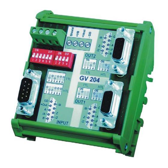
Impulse Splitter for Incremental Encoders
• Programmable encoder input A, /A, B, /B, Z, /Z, for use with RS422 or
TTL differential signals or with HTL signals (differential or single-ended)
• Two encoder outputs (A, /A, B, /B, Z, /Z each), with individually programmable
output levels (TTL 5 V or HTL 10 - 30 V)
• Max. frequency 750 kHz (TTL) or 300 kHz (HTL)
• Power supply either 5 V DC or 10 - 30 V DC
• Aux. voltage output +5 V for encoder supply (with 10 -3 0V power supply)
GV20401a_e.doc / Sep-08
interface
GV204
Operating Instructions
Page 1 / 10
Advertisement
Table of Contents

Related Manuals for Motrona GV204


Summary of Contents for Motrona GV204
- Page 1 – motion – interface GV204 Impulse Splitter for Incremental Encoders • Programmable encoder input A, /A, B, /B, Z, /Z, for use with RS422 or TTL differential signals or with HTL signals (differential or single-ended) • Two encoder outputs (A, /A, B, /B, Z, /Z each), with individually programmable output levels (TTL 5 V or HTL 10 - 30 V) •...
- Page 2 Safety Instructions • This manual is an essential part of the unit and contains important hints about function, correct handling and commissioning. Non-observance can result in damage to the unit or the machine, or even in injury to persons using the equipment ! •...
-
Page 3: Table Of Contents
Table of Contents 1. Compatibility Hint ................... 4 2. Application ...................... 5 3. Block Diagram ....................5 4. Power Supply ....................6 4.1. Supply from an unstabilized 10 - 30 volts DC source 4.2. Supply from a stabilized +5 volts DC source 5. -
Page 4: Compatibility Hint
- GV202 (dual splitter with TTL Input) - GV203 (dual splitter with HTL input) The new GV204 model is fully compatible to the previous models with all functions, connections, dimensions and technical specifications. Merely the successor model provides an additional DIL switch to set the input format to either TTL or HTL level, which allows to replace both parent models by just one new model. -
Page 5: Application
The output signal level is individually selectable to 5 volts or to 10 - 30 volts, by corresponding DIL switch setting. 3. Block Diagram The subsequent block diagram shows all essential circuit details of a GV204 unit: Shield +V Output 2... -
Page 6: Power Supply
4. Power Supply Supply from an unstabilized 10 - 30 volts DC source 4.1. In general, the unit is supplied with an unstabilised DC voltage of 10 - 30 V, using the screw terminals +V and GND. In this case pin 4 of the input Sub-D-connector will also provide a +5 V auxiliary output for encoder supply (max. -
Page 7: Impulse Inputs
Other switch positions than shown above are reserved for special applications and must only be used upon advice of motrona. Where for encoder supply a voltage higher than 5.4 volts should be required, please apply an appropriate voltage to terminal +Vext. -
Page 8: Impulse Outputs And Output Levels
6. Impulse Outputs and Output Levels The output signals are available on the two Sub-D-connectors marked "OUT1" and OUT2" (female connectors on unit site). The pin assignment is shown in the block diagram and is also printed to the top side of the unit. The four-position DIL-Switch provides individual setting of the output levels for each of the two output channels. -
Page 9: Dimensions
7. Dimensions 2 3 4 5 6 12 3 4 (3.543’’) 85 (3.346’’) (1.496’’) (1.969’’) GV20401a_e.doc / Sep-08 Page 9 / 10... -
Page 10: Specifications
8. Specifications Power supply 10 - 30 V DC or 5 - 30 V DC Current consumption approx. 5 mA to 50 mA dependent on input voltage and output loads (always with the aux. encoder supply output unloaded) Aux. output +5.4 volts, max.
Need help?
Do you have a question about the GV204 and is the answer not in the manual?
Questions and answers