Table of Contents
Advertisement
Quick Links
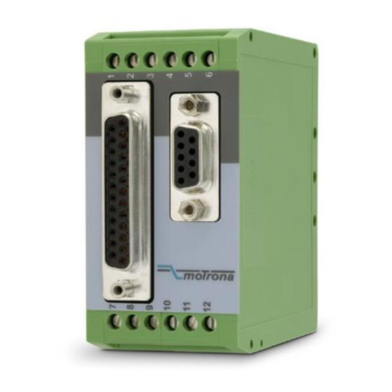
Operating Manual
Universal SSI / RS232 signal converter for operation with absolute SSI sensors and encoders
Product Features:
Converts SSI data as well as serial data to parallel binary, Gray oder BCD data format
Linearization facilities by freely programmable in-/output curves
Additional facilities like bit-blanking, round-loop-operation etc.
Parallel output 25 bits (push-pull, short circuit proof)
RS232 interface for serial readout of the sensor data
SSI: Master or Slave operation
18 to 30 VDC power supply
motrona GmbH, Zeppelinstraße 16, DE - 78244 Gottmadingen, Tel. +49 (0) 7731 9332-0, Fax +49 (0) 7731 9332-30, info@motrona.com, www.motrona.com
IP251
Advertisement
Table of Contents

Subscribe to Our Youtube Channel
Related Manuals for Motrona IP251


Summary of Contents for Motrona IP251
- Page 1 RS232 interface for serial readout of the sensor data SSI: Master or Slave operation 18 to 30 VDC power supply motrona GmbH, Zeppelinstraße 16, DE - 78244 Gottmadingen, Tel. +49 (0) 7731 9332-0, Fax +49 (0) 7731 9332-30, info@motrona.com, www.motrona.com...
- Page 2 Smaller corrections and modulations Legal notices: All contents included in this manual are protected by the terms of use and copyrights of motrona GmbH. Any reproduction, modification, usage or publication in other electronic and printed media as well as in the internet requires prior written authorization by motrona GmbH.
-
Page 3: Table Of Contents
Table of Contents 1. Safety Instructions and Responsibility ............4 1.1. General Safety Instructions ................... 4 1.2. Use according to the intended purpose ..............4 1.3. Installation ......................5 1.4. Cleaning, Maintenance and Service Notes ............5 2. Introduction ....................6 2.1. -
Page 4: Safety Instructions And Responsibility
1. Safety Instructions and Responsibility 1.1. General Safety Instructions This operation manual is a significant component of the unit and includes important rules and hints about the installation, function and usage. Non-observance can result in damage and/or impairment of the functions to the unit or the machine or even in injury to persons using the equipment! Please read the following instructions carefully before operating the device and observe all safety and warning instructions! Keep the manual for later use. -
Page 5: Installation
For placement, wiring, environmental conditions as well as shielding and earthing/grounding of the supply lines the general standards of industrial automation industry and the specific shielding instructions of the manufacturer are valid. Please find all respective hints and rules on www.motrona.com/download.html --> “[General EMC Rules for Wiring, Screening and Earthing]”. -
Page 6: Introduction
2. Introduction IP251 represents a small and low-cost, but highly performing converter for industrial applications, where the information of a sensor or encoder with SSI interface needs to be converted to a parallel signal or a serial RS232 data format. Also it is possible to convert serial RS232 data to a parallel format. -
Page 7: Connections
We recommend to connect the screen to GND and earth potential on both sites. 4.2. SSI encoder, Slave operation With this mode, the IP251 converter operates in parallel to another unit, acting as a „listener“ to the existing data communication. Quite according to need, the common potential of the master can be connected to terminal 4 (GND), or remain open for fully differential operation. -
Page 8: Parallel Outputs
4.4. Parallel outputs The unit provides 25 push-pull outputs which are short-circuit proof. The separate common output voltage for the outputs must be applied to screw terminal 1 (COM+). The maximum voltage to COM+ should not exceed +27 V, otherwise no continuous short-circuit proof of the outputs can be guaranteed. -
Page 9: Serial Interface
For PC setup and for serial readout of the encoder position, a serial RS232 interface is available. The serial interface allows to operate and setup the unit as well as readout the encoder position by a PC or Notebook. IP251 PC connection cable (female) (male) Ip251_02b_oi_e.doc / Apr-16... -
Page 10: Dil Switch Settings
5. DIL Switch Settings The DIL switch located on the top site of the unit provides encoder settings and customer- specific settings of the desired operation modes. Changes of switch settings will become active only after the next power-up cycle! 1 2 3 4 5 6 7 8 Set Default: OFF: Unit loads default settings with every power-up cycle... -
Page 11: Extended Functions With Pc Setup
In case your text and color fields remain empty and the headline says „OFFLINE“, you must verify your serial settings. To do this, select „Comms“ from the menu bar. Ex factory, all motrona units use the following serial standard settings: Unit No. 11, Baud rate 9600, 1 start/ 7 data/ parity even/ 1 stop bit If the serial settings of the unit should be unknown, you can run the „SCAN“... -
Page 12: Self-Test
6.1. Self-Test On your PC screen, in the ”Outputs” field, you find several indicator boxes. When the ”Self-test passed” box lights red, this indicates that the unit has correctly initialized and is ready to work. The fields ”Status SSI-CLK” and ”Status SSI-Data” indicate that the clock and data lines work correctly (red color = o.k.) *) You may observe that these boxes blink, because of the update cycle of your PC. -
Page 13: Parameters
You can read out the actual SSI position of the encoder at any time from the serial link. For setting of communication parameters (baud rate etc.) you need a PC. IP251 uses the DRIVECOM communication standard according to ISO 1745. Details about this protocol can be found in the file Serpro1a.doc, (available for Download from www.motrona.com) - Page 14 If you like to convert the SSI encoder data to the parallel output with a 7.2.2. different scaling: Example: encoder 16 Bit = 65536 steps to be converted to a range of 0 - 10 000 on the parallel output ...
-
Page 15: Ring Counter, Parameter "Round Loop
x-registers must follow continuously increasing settings, i.e. P1(x) must receive the lowest setting and P16(x) must receive the highest setting All entries use a percent format of xx.xxx% full scale. Setting 0.000% means zero output and setting 100.000% means full scale encoder output ... - Page 16 The zero position of the round-loop counter can be set by register “SSI-Offset” which allows settings between 0 and the Round-Loop value. Register “Direction” allows to set the counting direction of the round loop counter (0 = up, 1 = down). The following drawings explain the coherence between original SSI encoder data, Round-Loop setting, SSI-Offset and Direction register.
-
Page 17: More Parameters
The Round-Loop function is also suitable to suppress the encoder overflow, if you do not like to change the mechanical situation. As shown in the subsequent picture, you need to set the Round-Loop register to the full encoder resolution and then shift the zero transition by setting the SSI Offset correspondingly. - Page 18 Parameter Description SSI Low Bit: Defines the lowest bit (LSB) for evaluation when the bit blanking function is used. Must be set to “01” for full evaluation of the encoder range. SSI High Bit: Defines the highest bit (MSB) for evaluation when the bit blanking function is used.
- Page 19 Parameter Description SSI Baud Rate: Sets the communication speed of the SSI interface with SSI encoders. Setting range: 100 Hz to 1MHz. You are free to set any desired frequency between 0.1 kHz and 1000.0 kHz. For technical reasons however, in the upper frequency range with Master operation, the unit will only generate one of the following frequencies accurately: 1 000.0 kHz 888.0 kHz...
- Page 20 The subsequent drawing explains the timing with use of equidistant update mode with a SSI Wait Time setting of 3 ms. With equidistant operation mode, the SSI wait time setting is limited to maximum 90 ms. The shortest possible time for equidistant updating is 2 ms, due to internal processing times (SSI Wait Time set to 0.001).
- Page 21 SSI Error Bit: Defines the position of the error bit (if available with the encoder in use). no error bit available bit 13 represents the error bit bit 25 represents the error bit etc. Errors indicated by the encoder can be read out via serial code ;9 (semicolon nine, error indication = 2000hex).
-
Page 22: Parameters For Rs232 Settings
7.5. Parameters for RS232 settings Parameter Description Unit Number : Any address numbers between 11 and 99 * can be chosen (Factory setting = 11). Please note: The address must not contain a “0“ because these numbers are reserved for collective addressing. Serial Baud Setting Baud-Rate... - Page 23 For clarification of register codes see the following figure. The most important register codes are: Register ASCII SSI Value (HW) SSI Value Display Value Parallel Value IP251 Overview Legende - SSI Format Legende Legend Hardware (13,21,25 bit) Comments SSI Value (HW) (;0)
- Page 24 *) The serial port of the unit can operate in either “PC mode“ or “Printer mode“. With PC mode, the unit receives a request string and responds with a corresponding data string. For details of the protocol see separate description “SERPRO“.
-
Page 25: Test Functions
8. Test Functions When you select TEST from the TOOLS menu, you are able to verify the following data, by clicking to the corresponding field: Actual encoder position, DIL switch settings, Internal supply voltages, Parallel output state Additionally, the following registers can be recorded by using the monitor function: Ip251_02b_oi_e.doc / Apr-16 Page 25 / 28... -
Page 26: Technical Specifications
9. Technical Specifications Power supply: Input voltage: 18 … 30 VDC Protection circuit: reverse polarity protection Ripple: ≤ 10 % at 24 VDC Consumption: approx. 200 mA Connections: screw terminals, 1.5 mm² / AWG 16 Encoders / sensors: Usable types: absolute encoders (single-turn, multi-turn or comparable) Interface: SSI (6 …... -
Page 27: Dimensions
10. Dimensions 40 mm 91mm (3.583’’) (1.575’’) 74 mm (2.913’’) Front view Top view Side view Ip251_02b_oi_e.doc / Apr-16 Page 27 / 28... -
Page 28: Parameter List, Default Settings
11. Parameter List, Default Settings Parameter Min. value Max. value Default Pos. Char. Ser. Code X Operand -10.0000 +10.0000 1.0000 +/- 6 / Operand 10.0000 1.0000 +/- Operand -99999999 99999999 +/- 8 Linear In -99999999 +99999999 +/- 8 Linear Out -99999999 +99999999 10000...
Need help?
Do you have a question about the IP251 and is the answer not in the manual?
Questions and answers