Advertisement
Quick Links
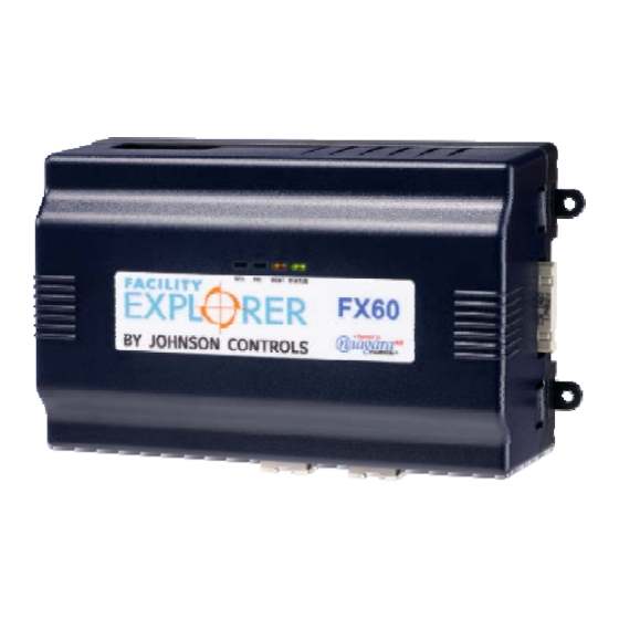
FX20/FX60 Supervisory Controllers
Application
The FX20 and FX60 are Web-based supervisory class
controllers in the Facility Explorer product family. The
FX20/FX60 manages networks of field controllers
using open communication protocols, such as N2,
L
W
®, and BACnet® protocols.
ON
ORKS
Figure 1: FX60 Supervisory Controller
North American Emissions Compliance
United States
This equipment has been tested and found to comply
with the limits for a Class A digital device pursuant to
Part 15 of the FCC Rules. These limits are designed to
provide reasonable protection against harmful
interference when this equipment is operated in a
commercial environment. This equipment generates,
uses, and can radiate radio frequency energy and, if
not installed and used in accordance with the
instruction manual, may cause harmful interference to
radio communications. Operation of this equipment in
a residential area is likely to cause harmful
interference, in which case the user will be required to
correct the interference at his/her own expense.
Canada
This Class (A) digital apparatus meets all the
requirements of the Canadian Interference-Causing
Equipment Regulations.
Cet appareil numérique de la Classe (A) respecte
toutes les exigences du Règlement sur le matériel
brouilleur du Canada.
© 2014 Johnson Controls, Inc.
Part No. 24-10174-77, Rev. D
Installation Instructions
Installation Instructions
Issue Date
Installation
Parts Included
Unpack the FX20/FX60 and accessories
(power module, option cards), if ordered. Inspect the
contents of the packages for damaged or missing
components. If damaged, notify the appropriate carrier
and return any damaged components for repair or
replacement.
Included in this package are the following items:
FX Supervisory Series controller
Hardware bag containing a grounding wire with
quick disconnect 0.187 in. (4.75 mm) female
connector.
Power module (if ordered). The power module
may be one of the following:
LP-FXPM24-0
(24 VAC, DIN rail mountable)
LP-FXPM263-0
(90-263 VAC, DIN rail mountable)
LP-FXPMUS-0
(90-240 VAC, with U.S. wall adapter)
LP-FXPMEU-0
(90-240 VAC, with European wall adapter)
LP-FXPMUK-0
(90-240 VAC, with U.K. wall adapter)
Communication cards (if ordered)
LP-FXLONFTT-1
LP-FXRS232-0
LP-FXRS485-0
LP-FXMDM-0
LP-FXWTC-0
Expansion Input/Output (NDIO) Modules
(if ordered)
LP-FXNDIO16-0
LP-FXNDIO34-0
LP-FXRIO16-0
April 9, 2014
1
www.johnsoncontrols.com
Advertisement

Related Manuals for Johnson Controls Facility Explorer FX20


Summary of Contents for Johnson Controls Facility Explorer FX20
- Page 1 Equipment Regulations. (if ordered) Cet appareil numérique de la Classe (A) respecte LP-FXNDIO16-0 toutes les exigences du Règlement sur le matériel LP-FXNDIO34-0 brouilleur du Canada. LP-FXRIO16-0 © 2014 Johnson Controls, Inc. Part No. 24-10174-77, Rev. D www.johnsoncontrols.com...
- Page 2 Materials and Special Tools Needed Safety Precautions You may require the following materials and tools for The following information relates to the installation and installation: startup of the FX20/FX60. DIN Rail: type NS35/7.5 (35 x 7.5 mm) and DIN rail end clips.
- Page 3 Static Discharge Precautions Accessories Static charges produce voltages high enough to The FX20/FX60 has a 20-pin, right-angle, Euro-DIN damage electronic components. The microprocessors connector that accepts accessory modules. The and associated circuitry within a FX20/FX60 are connector provides power and signal lines to any sensitive to static discharge.
- Page 4 Table 1: Accessory Module Details Model Description Notes LP-FXPM24-0 Power module for FX20/FX60 Install only one power module per FX20/FX60, regardless of type. 24 VAC/DC, DIN rail mountable LP-FXPM263-0 Power module for FX20/FX60 Install only one power module per FX20/FX60, regardless of type.
- Page 5 Mounting Mount the unit on a 35-mm wide DIN rail (recommended). The FX20/FX60 unit base and Mount the FX20/FX60 in a location that allows its accessories have molded DIN rail slots and clearance for wiring, servicing, and module removal. locking clips.
- Page 6 6.719 in. (170.66 mm) 0.170 in. Diameter (4.32 mm) FX-20/60 3.75 in. (95.25 mm) 2.50 in. Note: Electronic and printed versions of t his document may not show 4.00 in. the dimensions to scale. Verif y all measurements before drilling. (63.50 mm) (101.6 mm) DIN mounting is recommended over tab mounting.
- Page 7 Figure 4: Using End Clips to Secure Modules Figure 3: DIN Rail Mounting Figure 5: Mounting Accessories 7 FX Supervisory Controller Installation Instructions...
- Page 8 Removing and Replacing the Cover Board Layout The FX20/FX60 cover is removable. You must remove See Figure 6 for the location of Light-Emitting Diodes the FX20/FX60 cover to connect the battery on a new (LEDs), option slots, and other features of the unit, to replace the battery on an existing unit or to FX20/FX60.
- Page 9 Expansion Options The FX20/FX60 provides for field-installable expansion with two options: CAUTION: Risk of Property Damage. Do not apply power to the system before checking Option Cards: these are installed on connectors all wiring connections. Short circuited or improperly inside the FX20/FX60 base unit.
- Page 10 Table 3: COM Port and Option Slot Assignments for FX20/FX60 Option Cards Option Slot 1 Option Slot 2 Onboard RS232 Onboard RS485 None None COM1 COM2 RS-232 = COM3 None COM1 COM2 RS-232 = COM3 RS-232 = COM4 COM1 COM2 RS-232 = COM3 RS-485 = COM4, COM5 COM1...
- Page 11 Mounting Option Cards Wiring For complete details, refer to the specific mounting See Figure 6 to locate connectors and other and wiring guide that shipped with the option card. components on the FX20/FX60. Follow these basic steps: Make connections to the FX20/FX60 in the following 1.
- Page 12 Power Wiring Wall Mount Power Module The FX20/FX60 must be powered by an approved 15 Three models of wall power modules are available: VDC power source. This can come from one of the United States (U.S.), European Union (EU), and following: United Kingdom (U.K.).
- Page 13 LP-FXPM (cov er removed) FX-20/FX-60 Earth Ground 24 VDC Pow er Supply Dedicated 24 VAC transformer (polarity not critical) Neither side of secondary tied Neither side tied to to earth ground. earth ground. Line voltage 24 VDC 24 VAC (Mains) Figure 7: LP-FXPM Power Module Wiring Connections Located at the bottom of the power module is a LP-FXPM263-0 Line Voltage Power Module...
- Page 14 Remove cover. 6-pin connector not used. FX-20/FX-60 or last NDIO-16. AC Input 120 or 240 VAC 50-60 Hz Single Phase Line Earth Ground Neutral Figure 8: LP-FXPM263-0 Line Voltage Power Module Wiring Connections To wire the DIN rail mount line voltage power module, see Figure 8 and follow these instructions: CAUTION: Risk of Property Damage.
- Page 15 Communications Wiring Prior to connecting cables, provide strain relief for them to prevent damage to the controller. Connect communications wiring to the ports on the bottom of the FX20/FX60. Ethernet (RJ-45) Primary Ethernet (RJ-45) Battery in bracket LAN 2 LAN 1 (on top of option cards, if any) 20-pin...
-
Page 16: Setup And Adjustments
Table 4: Serial Port Pinouts Pinout References Signal DB-9 Base RS-485 Plug Pin Port (COM2) Pinouts DB-9 Plug (Male) Data carrier detect Receive data Transmit data Data terminal ready Ground Data set ready Request to send Clear to send Not used on the FX20/FX60 RS-485 Port Setup and Adjustments An RS-485 non-isolated port uses a 3-position, screw... -
Page 17: Operation
Connecting the Backup Battery About the Battery With the cover removed from the FX20/FX60, locate The FX20/FX60 is provided with a custom, 10-cell the red and black wires with a plug on the backup NiMH battery pack mounted to the unit under the battery. - Page 18 Niagara build, a license, and four LED should blink about once per second. If the BEAT Johnson Controls® specific Java® Archive (JAR) files. LED stays on constantly, does not light, or blinks very With these components in place, you only need to...
- Page 19 IP Address Initially, you use these default credentials to open a platform connection (log in) to the FX20/FX60. Like the When shipped, a new FX20/FX60 Series controller is factory-assigned IP address, default credentials are pre-configured with an IP address of 192.168.1.149 intended to be temporary.
-
Page 20: Repair Information
Cleaning Remove the old battery and bracket assembly by removing the four screws holding it in place. Set If dust or metal filings are present inside the unit, clean the screws aside for later. with vacuum or compressed air. Otherwise, no cleaning inside the unit is required. - Page 21 Remove any screws fastening ensure proper credit for a FX20/FX60 still under the FX20/FX60 and remove the FX20/FX60. warranty, contact the Johnson Controls Product Sales Remove the cover from the old FX20/FX60 (see Operations Team for return authorization. Removing and Replacing the Cover). Note the position of installed option boards, if any.
- Page 22 Building Efficiency 507 E. Michigan Street, Milwaukee, WI 53202 Johnson Controls® is a registered trademark of Johnson Controls, Inc. All other marks herein are the marks of their respective owners. © 2014 Johnson Controls, Inc. FX20/60 Supervisory Controllers Installation Instructions...
Need help?
Do you have a question about the Facility Explorer FX20 and is the answer not in the manual?
Questions and answers