Table of Contents
Advertisement
TABLE OF CONTENTS
General Information ............................................................1
Installation .......................................................................2-4
Wiring ..............................................................................5-6
Unit Configuration .........................................................7-23
Troubleshooting ..........................................................24-25
Electrical Specifications ....................................................25
Agency Approvals .............................................................26
Intrinsically Safe Installations............................................26
Dimensional Specifications...............................................27
Replacement Parts............................................................27
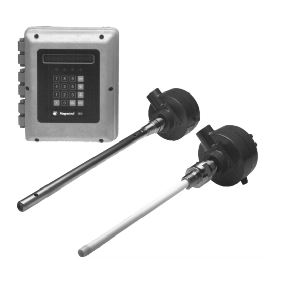
The Kotron II Series 801 Transmitter is a new generation RF
Capacitance transmitter that offers the user unparalleled
power. The Series 801 can interface with two separate
vessels, essentially making it a mini-multiplexer, while soft-
ware mathematics allows for the Sum or Difference of the
two signals.
TM
Kotron
II
Series 801
RF Capacitance
Transmitter For
Level/Flow/Volume
Instruction Manual and Parts List
MODEL IDENTIFICATION
Each Series 801 capacitance transmitter has a nameplate on
which the model number of the unit is shown. The model
number is coded to identify the options of that specific unit.
KOTRON II
SERIES 801 TRANSMITTER
NUMBER OF PROBES/OUTPUT
2 = 1 probe, One 4-20mA (isolated),
RS-232
4 = 2 probes, One 4-20mA (isolated),
RS-232
INPUT POWER
0 = 120 VAC
1 = 240 VAC
2 = 24 VDC
3 = 120 VAC with heater and thermostat
4 = 240 VAC with heater and thermostat
DIGITAL, 16 CHARACTER, LCD DISPLAY
REMOTE MOUNTING CONFIGURATION
1 = NEMA 4X
4 = NEMA 4X with I.S. probe circuit
HOUSING
A = NEMA 4X Noryl (electronics)
w/stainless steel remote probe housing
N =NEMA 4X Noryl (electronics)
w/aluminum sand cast remote probe housing
(4) 10 AMP SPDT RELAYS
OPTIONS
0 = None
2 = 31-day Data Logger (Smart Watch)
PRINCIPLE OF OPERATION
The amount of capacitance developed in any application is
determined by the size (surface area) of the probe, the dis-
tance from the probe to its ground reference, and the dielec-
tric constant of the medium being measured.
Considering that the probe's mounting position is fixed, and
the dielectric value of the medium is constant, the amount of
capacitance developed in any vessel becomes dependent
upon the probe's diameter and length.
As a medium rises and falls in the tank, the amount of
capacitance developed between the sensing probe and the
ground reference also rises and falls. The Pulsatel circuit,
mounted on the probe, changes the capacitance signal to a
digital signal which can then be sent to the main electronics
located up to 2500 feet (760 M) away.
801 -
3
-
4
Advertisement
Table of Contents
Troubleshooting

Related Manuals for Magnetrol Kotron II Series 801


Summary of Contents for Magnetrol Kotron II Series 801
-
Page 1: Table Of Contents
The Kotron II Series 801 Transmitter is a new generation RF upon the probe's diameter and length. Capacitance transmitter that offers the user unparalleled power. -
Page 2: Installation
INSTALLATION LOCATION NOTE: These comments also apply to glass-lined metal walled tanks. Kotron II Series 801 transmitters should be located with easy access for service, calibration and monitoring. The Vertical Mounting electronics should not be exposed to ambient temperatures as follows: below -20°... - Page 3 INSTALLATION cont. MOUNTING PROCEDURE MOUNTING PROCEDURE cont. Transmitter Mounting Procedure Standard Rigid Probe There are two predrilled holes in the enclosure for connect- 1. Thread probe into mounting bushing on tank. ing 3/4" NEMA 4X conduit; one for power and one for the 2.
-
Page 4: Installation
INSTALLATION cont. MOUNTING PROCEDURE cont. MOUNTING PROCEDURE cont. Flexible Probe Flexible Probe cont. CAUTION: Flexible probes are shipped with the CAUTION: Check probe terminal connection careful- cable clamp and the probe nut hand tightened. The ly to be certain lug will not short to packing gland or interfere with assembly of remote housing to probe. -
Page 5: Wiring
ELECTROSTATIC DISCHARGE (ESD) HANDLING PROCEDURE Magnetrol’s electronic instruments are manufactured to the 2. Use a grounding wrist strap when installing and remov- highest quality standards. These instruments utilize electron- ing circuit boards. A grounded workstation is also ic components which may be damaged by static electricity recommended. -
Page 6: Wiring
Refer to Figure 6. Spade lugs should be used. For optimum operator safety, observe the wiring colors To connect the preamplifier to the transmitter, use a shield- listed in Table 1. ed twisted pair of 22 gauge stranded conductors (Magnetrol P/N 009-7146-001). U.S. Europe U.K. -
Page 7: Unit Configuration
UNIT CONFIGURATION GENERAL CONFIGURATION INSTRUCTIONS GENERAL CONFIGURATION INSTRUCTIONS cont. The Kotron II Series 801 capacitance transmitter contains a Operator keypad microprocessor-based operator interface which allows for All Unit Configuration instructions in this manual will show easy configuration of level, flow or volume control applica- the local transmitter display exactly as it will appear to the tions. - Page 8 UNIT CONFIGURATION cont. NOTE: Prior to programming, it is suggested that the installation is reviewed and all data such as probe lo and probe hi points, desired units of measurement, 4–20 mA settings, and relay set points are written down to aid in the programming. SERIES 801 MAIN MENU STRUCTURE SINGLE PROBE OPERATION Series 801...
- Page 9 UNIT CONFIGURATION cont. NOTE: Prior to programming, it is suggested that the installation is reviewed and all data such as probe lo and probe hi points, desired units of measurement, 4–20 mA settings, and relay set points are written down to aid in the programming. SERIES 801 MAIN MENU STRUCTURE DUAL PROBE OPERATION Series 801...
- Page 10 UNIT CONFIGURATION cont. NOTE: Prior to programming, it is suggested that the installation is reviewed and all data such as probe lo and probe hi points, desired units of measurement, 4–20 mA settings, and relay set points are written down to aid in the programming. SERIES 801 MAIN MENU STRUCTURE DIFFERENCE OR SUM OPERATION Series 801...
- Page 11 UNIT CONFIGURATION cont. MEASURED VALUES MENU This menu is used to view present values being measured in the Series 801. The menu layout is shown below. Series 801 Measured Values Level Present measurement Volume (Volume mode only) Present measurement Flow (Flow mode only) Present measurement Totalizer (Flow mode only) Present measurement...
- Page 12 UNIT CONFIGURATION cont. SYSTEM CONFIG MENU cont. SYSTEM CONFIG MENU cont. Level Measurement Level Units This menu is used to configure the main control parame- Inches ters of the Series 801 for level measurement. Feet For the purposes of this manual, and to become familiar with Centimeters the configuration parameters of this unit, all instructions will be shown.
- Page 13 UNIT CONFIGURATION cont. SYSTEM CONFIG MENU cont. Level Measurement cont. Press ENT to display current Probe Lo value. Enter the exact low level of the process medium. Use proper level units (inches, centimeters, etc.) previously selected. When the desired value is displayed, press ENT to store the value. Supr Password? will be displayed if the selection is changed.
- Page 14 UNIT CONFIGURATION cont. SYSTEM CONFIG MENU cont. SYSTEM CONFIG MENU cont. Volume and Level Measurement Level Units This menu is used to configure the main control parameters Inches of the Series 801 for volume and level measurements. Feet For the purposes of this manual and to become familiar with Centimeters the configuration parameters of this unit, all instructions will be shown.
- Page 15 UNIT CONFIGURATION cont. SYSTEM CONFIG MENU cont. Volume and Level Measurement - Vessel Drawings Side View Top View Horizontal/Spherical Vertical/Flat Top View Side View Vertical/Conical Horizontal/Flat Side View Horizontal/Elliptical Spherical...
- Page 16 UNIT CONFIGURATION cont. SYSTEM CONFIG MENU cont. SYSTEM CONFIG MENU cont. NOTES: Custom Table 1. The Probe Lo and Probe Hi points are the most critical entries in the calibration procedure. Be sure of the val- If a custom table is selected, Password? will be displayed. ues before they are entered.
- Page 17 UNIT CONFIGURATION cont. SYSTEM CONFIG MENU cont. SYSTEM CONFIG MENU cont Level Units Flow and Level Measurement Inches This menu is used to configure the main control parame- Feet ters of the Series 801 for flow and level measurements. Centimeters For the purposes of this manual and to become familiar with Meters the configuration parameters of this unit, all instructions will...
- Page 18 UNIT CONFIGURATION cont. SYSTEM CONFIG MENU cont SYSTEM CONFIG MENU cont Flow and Level Flow Units Flow Element cont. Cubic Feet/Sec Rectangular/End Contractions (Rct/Cntr) Cubic Feet/Min Rectangular Cubic Feet /Hr Cipolletti Gallons/Min Palmer Bowlus 4" Gallons/Hr 6" Million Gals/Day 8" Cubic Meters/Sec 10"...
- Page 19 UNIT CONFIGURATION cont. SYSTEM CONFIG MENU cont. Flow and Level Measurement cont. Press ENT to display current Probe Lo value. Enter the exact low level of the process medium. Use proper level units (inches, centimeters, etc.) previously selected. When the desired value is displayed, press ENT to store the value. Remote rigid probe Supr Password? will be displayed if the selection is changed.
- Page 20 UNIT CONFIGURATION cont. I/O CONFIGURATION MENU I/O CONFIGURATION MENU cont This menu is used to configure relay settings, 4–20 mA cur- Please refer to the Relay Settings menu layout at bottom rent output, totalization, and communications parameters of left for the configuration instructions below. the Series 801.
- Page 21 UNIT CONFIGURATION cont. I/O CONFIGURATION MENU cont I/O CONFIGURATION MENU cont Password? will be displayed if any of the selections have Totalizer (Flow Mode Only) been changed. Your chosen password must be entered at Control w/Probe 1 this time. The unit will display the current menu item - Relay (Dual Probes, Difference, and Summing Settings.
- Page 22 ENTer to set and then asks for the supervisory password. Enter Tag This menu shows the present tag - Magnetrol 801. (If utiliz- ing multiple probes, Probe 1 Select will be displayed. A tag may be entered for each probe).
-
Page 23: Unit Configuration
UNIT CONFIGURATION cont. DIAGNOSTICS MENU DIAGNOSTICS MENU cont. This menu is used to provide the user with testing the func- Extended Errors cont. tionality and providing useful information for troubleshooting BIT 1: A one (1) will appear if the Series 801 fails the inter- of the unit. -
Page 24: Troubleshooting
TROUBLESHOOTING These are troubleshooting displays which may appear on the Series 801. SYMPTOM PROBLEM SOLUTION The probe high point being entered has a lower CAP TOO LO Raise the probe high point being entered. capacitance than the present lo point. The probe low point being entered has a higher CAP TOO HI Lower the probe low point being entered. -
Page 25: Electrical Specifications
TROUBLESHOOTING cont. SYMPTOM PROBLEM SOLUTION CCO/PROBE Consult Extended Errors section on page 23 of Various (1) or (2) FAIL this manual. If you need the real time functions, contact The real time clock was not found on the board. NO CLOCK PRESENT the factory to determine if your unit was ordered No data logging or time sampling is allowed. -
Page 26: Agency Approvals
Non-hazardous indoor/outdoor indoor/outdoor TYPE 4X 801-XX31-N4X NEMA 4X IP65 Intrinsically Safe Remote indoor/outdoor TYPE 4X Intrinsically Safe Remote when installed per Magnetrol (indoor/outdoor, NEMA 4X IP65 drawing 99-5043-001 CSA* when installed per Magnetrol Class I, II & III 801-XX34-N4X drawing 99-5043-001 Groups A, B, C, D, E, F, &... -
Page 27: Dimensional Specifications
SPECIFICATIONS cont. DIMENSIONAL SPECIFICATIONS inches (mm) 4.63 4.63 9.50 (118) Dia. (118) Dia. (241) 3.00 3.00 (76) (76) 2.75 2.75 (70) (70) Optional 3/4" NPT 3/4" NPT 3.23 Optional Mounting 4.67 (82) Mounting Flange (119) 9.50 13.00 Flange (241) (330) 3/4"... -
Page 28: Description
Note: See ESD Handling Procedure on page 5. damage will be allowed. 5300 Belmont Road • Downers Grove, Illinois 60515-4499 • 630-969-4000 • Fax 630-969-9489 • www.magnetrol.com 145 Jardin Drive, Units 1 & 2 • Concord, Ontario Canada L4K 1X7 • 905-738-9600 • Fax 905-738-1306 Heikensstraat 6 •...
Need help?
Do you have a question about the Kotron II Series 801 and is the answer not in the manual?
Questions and answers