Magnetrol Eclipse 706GWR Safety Manual
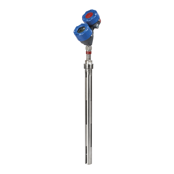
Radar level transmitter
Hide thumbs
Also See for Eclipse 706GWR:
- Installation and operating manual (108 pages) ,
- Operating manual (48 pages)
Table of Contents
Advertisement
Quick Links
Download this manual
See also:
Operating Manual
SIL Safety Manual
for Eclipse
High Performance uided Wave
Radar Level Transmitter
This manual complements and is intended to be used with the
Magnetrol
®
Eclipse
®
Model 706 High Performance Guided Wave
Radar Installation and Operating manual ( ulletin 57- 606).
pplication
The HART
version of the ECLIPSE Model 706
®
Guided Wave Radar level transmitter can be applied in
most process or storage vessels, bridles, and bypass
chambers up to the probe's rated temperature and pres-
sure. It can be used in liquids, slurries, or solids with a
dielectric constant in the range 1.4–100 to meet the
safety system requirements of IEC 61508 (Edition 2.0,
2010) and IEC 61511-1.
Benefits
The MAGNETROL ECLIPSE Model 706 (HART)
transmitter provides the following benefits to your
operation:
• Suitable for use to SIL 2 (Safe Failure Fraction =
93%) as standalone device independently assessed
(hardware assessment) by exida as per IEC 61508/
IEC 61511-1.
• Probe designs to +850 °F (+454 °C), 6250 psig
(430 bar) and full vacuum.
• Cryogenic applications to -320 °F (-190 °C).
• Intrinsically safe, Explosion-proof and Non-Incendive
approvals.
• Quick connect/disconnect probe coupling.
Model 706
®
Advertisement
Table of Contents

Subscribe to Our Youtube Channel
Related Manuals for Magnetrol Eclipse 706GWR


Summary of Contents for Magnetrol Eclipse 706GWR
- Page 1 1.4–100 to meet the safety system requirements of IEC 61508 (Edition 2.0, 2010) and IEC 61511-1. Benefits The MAGNETROL ECLIPSE Model 706 (HART) transmitter provides the following benefits to your operation: • Suitable for use to SIL 2 (Safe Failure Fraction =...
-
Page 2: Table Of Contents
Eclipse Model 706 High Performance Guided Wave Radar Level Transmitter ® SIL Safety Manual for Eclipse Model 706 ® Table of Contents 1.0 Introduction ..............3 6.5.1 General............7 1.1 Product Description ..........3 6.5.2 Configuration..........7 1.2 Theory of Operation..........3 6.5.3 Write Protecting /Locking ......7 1.3 Determining Safety Integrity Level (SIL) ....3 6.6 Site Acceptance Testing ..........7 pplicable Models ............4... -
Page 3: Introduction
Introduction Product Description The ECLIPSE Model 706 High Performance Guided Wave Radar Level Transmitter is a loop-powered, 24 VDC level transmitter, based on Guided Wave Radar (GWR) technology. Table 1 NOTE: For Safety Instrumented Systems usage, it is assumed that the ECLIPSE 706 Model Number 4–20 mA output is used as the primary safety variable. -
Page 4: Pplicable Models
• The only unsafe mode is when the unit is reading an incorrect level within the 4–20 mA range (> ±2% deviation). • MAGNETROL defines a safe failure as one in which the 4–20 mA current is driven out of range (i.e., less than 3.8 mA or greater than 21.5 mA). -
Page 5: Mean Time To Restoration (Mttr)
Overvoltage Category II is a local level, covering appliances, portable equipment, etc., with smaller, transient, overvoltages than those characteristic of Overvoltage Category III. This category applies from the wall plug to the power-supply isolation barrier (transformer). As the typical plant environment is Overvoltage Category II, most equipment evaluated to the requirements of IEC/EN 61010 are considered to belong in that classification. -
Page 6: Environmental
6.1.2 Environmental Refer to Installation and Operating Manual 57-606 for Environmental limitations. 6.1.2.1 Storage The device should be stored in its original shipping box and not be subjected to temperatures outside the storage temperature range of -50 to +185 °F (-46 to +85 °C). Installation Refer to the Model 706 Installation and Operating Manual 57-606 manual for complete installation instructions. -
Page 7: Configuration
Configuration 6.5.1 General The ECLIPSE Model 706 Transmitter can be configured via the local display, a HART compatible handheld terminal, or a personal computer using PACTware and the associated ™ DTM. 6.5.2 Configuration Ensure the parameters have been properly configured for the application and probe. -
Page 8: Recording Results
200 mS). A message will appear and the output current will be driven to 3.6 or 22mA (customer dependent) upon detection of a Fault. 6.8.2 Troubleshooting Report all failures to the MAGNETROL Technical Support Department. Refer to the Model 706 Installation and Operating Manual Bulletin 57-606 for troubleshooting device errors. -
Page 9: Recording Results
7.1.3 Recording Results Results of the Proof Test should be recorded for future reference. 7.1.4 Suggested Proof Test The suggested proof test below, in combination with the built-in automatic diagnostics, will detect 98% of possible DU failures in Model 706-511x-xxx. Step Action Bypass the PLC or take other action to avoid a false trip. - Page 10 Step Action Use the DIAGNOSTICS menu to observe the present Echo Curve. Confirm that the ECHO Waveform is normal. The echo curve is dependent on the type of probe, the installation conditions and the level of process on the probe. Comparison of the present Echo Curve to the one stored at the time of commis- sioning the unit gives additional confidence of the normal operation of the unit.
-
Page 11: Ppendices
SIL Declaration of Conformity Functional safety according to IEC 61508/IEC 61511. Magnetrol International, Incorporated, 705 Enterprise Street, Aurora, Illinois 60504, declares as the manufacturer, that the level transmitter: Guided Wave Radar (4–20 mA) Model 706-51x-xxx is suit- able for the use in safety instrumented systems according to... -
Page 12: Fmeda Report: Exida Management Summary
FMED Report: exida Management Summary 57-656 SIL Safety Manual for ECLIPSE Model 706... - Page 13 57-656 SIL Safety Manual for ECLIPSE Model 706...
-
Page 14: Specific Model 706 Values
Specific Model 706 Values Specific Model 706 ECLIPSE Product Model 706-51Ax-xxx SIL 2 93.0% PFD avg 6.67E-04 Annually Proof Test Interval (refer to PFD Graph below) PFD Graph The resulting PFD Graph generated from the exSILentia tool for a proof test interval of one year is displayed below. value for a single, Model 706-511x-xxx with proof test intervals of one year. -
Page 15: Report: Lifetime Of Critical Components
Report: Lifetime of Critical Components According to section 7.4.9.5 of IEC 61508-2, a useful life- time, based on experience, should be assumed. Although a constant failure rate is assumed by probabilistic estimation method, this only applies provided that the use- ful lifetime of components is not exceeded. - Page 16 84.00.01-2004” Disclaimer The SIL values in this document are based on an FMEDA analysis using exida’s SILVER Tool. MAGNETROL accepts no liability whatsoever for the use of these numbers or for the correctness of the standards on which the general calculation methods are based.
Need help?
Do you have a question about the Eclipse 706GWR and is the answer not in the manual?
Questions and answers