Table of Contents
Advertisement
Quick Links
Advertisement
Table of Contents

Related Manuals for RGBlink FLEX RS1


Summary of Contents for RGBlink FLEX RS1
- Page 1 FLEX RS1 USER MANUAL Article No: RGB-RD-UM-FLEX RS1 E001 Revision No: V1.0...
-
Page 2: Table Of Contents
2.2 Plugging in Main Power......................10 Chapter 3 Using Your Product........................11 3.1 XPOSE Operation........................11 3.1.1 XPOSE Installation......................11 3.2 XPOSE Controls FLEX RS1.......................16 3.2.1 Login in XPOSE........................ 16 3.2.2 Web Links...........................18 3.2.3 Connect Device......................... 18 3.2.4 System Setting........................19 3.2.4.1 Connect Setting..................... -
Page 3: Declarations
30 days after the transfer of risks. In the event of justified notice of compliant, RGBlink can repair the fault or provide a replacement at its own discretion within an appropriate period. If this measure proves to be impossible or unsuccessful, the purchaser can demand a reduction in the purchase price or cancellation of the contract. -
Page 4: Operators Safety Summary
Installation Safety Summary Safety Precautions For all FLEX RS1 installation procedures, please observe the following important safety and handling rules to avoid damage to yourself and the equipment. To protect users from electric shock, ensure that the chassis connects to earth via the ground wire provided in the AC power Cord. - Page 5 The AC Socket-outlet should be installed near the equipment and be easily accessible. Unpacking and Inspection Before opening FLEX RS1 shipping box, inspect it for damage. If you find any damage, notify the shipping carrier immediately for all claims adjustments. As you open the box, compare its contents against the packing slip.
-
Page 6: Chapter 1 Your Product
HDMI to DVI HDMI Cable DVI Cable Cord Cable RJ 45 to USB Cable Antistatic DB9 Cable Note: AC Power Cable supplied as standard according to destination market. USB is contained on the Warranty/Registration Card. Please keep. User Manual FLEX RS1... -
Page 7: Product Overview
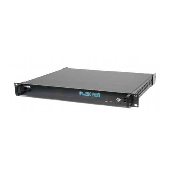
FLEX RS1 enables creative video split including any degree rotation, edge blending for the projector and video wall hard splicing. FLEX RS1 supports up to 4K2K, the UHD input resolution. It supports two HDMI inputs, a dual-link DVI input, a Display Port input and four DVI outputs. -
Page 8: Front Panel
1.2.1 Front Panel Panel Instruction SIGNAL Signal indicator lights when device USB Interface To upgrade the device has connected with input signal. POWER Power indicator lights when device has power supply. User Manual FLEX RS1... -
Page 9: Back Panel
4 DVI outputs Control Interface SLAVE IN and OUT SLAVE IN Connect to XPOSE software by . RGBlink supports a USB to RS 232 converter and the RS 232 to RJ11 cable for this connection, as standard accessories. ART-NET IN Connect to ARTNET(DMX) controller. -
Page 10: Dimension
1.2.3 Dimension Following is the dimension of FLEX RS1for your reference: User Manual FLEX RS1... -
Page 11: Chapter 2 Installing Your Product
Connect signals to the product (ensure all devices are powered off first). Tighten connector screws/locks where provided.Connect to XPOSE software by DB9 to RJ45cable. RGBlink provides a DB9 to RJ45 cable for this connection, as a standard accessories. Please check in the package for this cable.. -
Page 12: Chapter 3 Using Your Product
Operating system: Windows 7 or above (full version, not Ghost version or compact version) Double click icon, it will pop-up the installer language box, select the language, for example, select “English”, and click “OK” to confirm. Click “Next” to install: FLEX RS1 User Manual... - Page 13 Select “Browse...” to select the XPOSE software install location: Click “Install”: FLEX RS1 User Manual...
- Page 14 During installation, it will pop up the window of Install Shield Wizard for Virtual Com port: If user install the XPOSE software for the first time, click “Next” FLEX RS1 User Manual...
- Page 15 Then click “Install", as shown in the figure below: Click “Finish” and complete the installation, as shown in the figure below: Select”Finish”and the device driver is completed installed,: FLEX RS1 User Manual...
- Page 16 Click “Finish” and is ready to run the XPOSE : FLEX RS1 User Manual...
-
Page 17: Xpose Controls Flex Rs1
Double click the icon on the desktop. Login interface will pop up, the user name is Admin, and there is no password, select “FLEX RS1”, and enter the XPOSE by clicking “Login”. If user want to change the language, click the drop down arrow after “Language” and there are “English”... - Page 18 XPOSE management software interface is shown as follows: XPOSE management software contains the functions including: Operation Mode, Input Settings, Output Settings, System Settings and Log out. In the following parts come with the detail. FLEX RS1 User Manual...
-
Page 19: Web Links
“Download” will be found. 3.2.3 Connect Device The remote controller PC which runs XPOSE connects with Flex RS1 by the USB to the RS 232 converter and the RS 232 to RJ45 cable (with the standard accessories). FLEX RS1... -
Page 20: System Setting
3.2.4 System Setting Click “System Setting” in the main interface: 3.2.4.1 Connect Setting Click “Connect Setting”: Select ”COM Port” and “Baud Rate”, click the drop down arrow after them, and click “OK”. FLEX RS1 User Manual... -
Page 21: Ip Setting
Default “Auto get IP address”. Users can also set IP address, Mask and GateWay manually. This is usually used if one computer control some devices or remote control. It takes effect after reboot the software if change IP through network. FLEX RS1 User Manual... -
Page 22: System Information
Display the device version information. Including Model Number, Serial Number, IP Address, firmware version, etc. 3.2.4.4 Factory Reset Click “Factory Reset”, and pop-up window as follows: Click “OK” or “Cancel” to confirm or cancel the IP reset. FLEX RS1 User Manual... -
Page 23: Fan Control
3.2.4.5 Fan Control Click “Fan Control”, and pop-up window as follows: Enable or disable the Auto Fan Control, set Fan Speed and click ”Set”, that will load. FLEX RS1 User Manual... -
Page 24: Output Settings
Test Pattern and DE Setting are included in output settings, specific as follows: 3.2.5.1 Test Pattern Click the “Test Pattern”, and pop-up window as follows: Click the drop down arrow of “Output”and select any Ports among the four boards. FLEX RS1 User Manual... - Page 25 Click the drop down arrow of “Color Choose”and select any Ports among the sixteen boards. FLEX RS1 User Manual...
-
Page 26: De Setting
(6) De Swith: Select on or off. (7) X, Y, Width, Height: Select the as requirement. (8) LinePolarity: Select the Pos or Neg as requirement. (9) ScenePolarity: Select the Pos or Neg as requirement and click ”Set” to confirm. FLEX RS1 User Manual... -
Page 27: Input Setting
Under the ‘Work Mode” of 4K x 2K, users can only choose one input. Under the “Work Mode” of 4K x 1K or 2K x 1K,Users can choose two same input or two different input. See the example below when users select 4K x 1K “Work Mode”. FLEX RS1 User Manual... - Page 28 Dual DVI/HDMI1.4/HDMI2.0/DP1.2 Port EDID Set. After choosing Input type, users can do corresponding port EDID set of Width, Height and Frequency. FLEX RS1 User Manual...
-
Page 29: Operation Mode
3.2.7 Operation Mode Click the “Operation Mode”, and enter the interface as follows: There are 3 working modes, including the Rotation Mode, Projection Mode, Independent mode. FLEX RS1 User Manual... -
Page 30: Independent Mode
B. Choose number directly: click the left or right window, select any layer and choose any number as X, Y, W, H to ensure accurate position and size. FLEX RS1 User Manual... - Page 31 Click drop down arrow of Port and select any port among the four boards. This mode allow set each port resolution independently. Click drop down arrow of “resolution” and select any resolution among the 15 boards. FLEX RS1 User Manual...
- Page 32 Users can choose Custom when the non standard resolution is proper. Width, Height and Frequency can be filled after users choose Custom. Select “Set All” if users want all the four outputs at same resolution. FLEX RS1 User Manual...
- Page 33 Independent mode is applied when each display independently show same or different content at same or different resolution. Each output is allowed to show mirror image under this mode. FLEX RS1 User Manual...
-
Page 34: Rotation Mode
3.2.7.2 Rotation Mode To exit current interface, just click the red cross on the right top. And go back to the Operation Mode interface. Click the “Rotation Mode”, and enter the following interface. FLEX RS1 User Manual... - Page 35 For example, when Disp Area 1 is selected and rotate it at 45 °, its finder frame is selected with 45 ° rotation. Users can select the display content for Disp Area by dragging the finder frame. FLEX RS1 User Manual...
- Page 36 Monitor, set monitor size and border size here. Sync to View Finder. Synchronize display area and finder frame. FLEX RS1 User Manual...
- Page 37 Save Script, Users can save the setting to computer or USB drive by clicking Load Script, users can load previously saved setting from computer or USB drive by clicking it. Reset, if the operation is not proper, reset to clear former setting. FLEX RS1 User Manual...
-
Page 38: Projection Mode
Finder Frame 3 allow users to key in exact pixels of right and top Finder Frame 4 allow users to key in exact pixels of left and top Projection mode is applied to adjust the border blending of each projection output display to make perfect splicing . FLEX RS1 User Manual... - Page 39 Gamma Users can set R,G,B value for each output. Value range from 0~255 Sync Reconnect XPOSE to device and synchronize data from device to XPOSE. FLEX RS1 User Manual...
-
Page 40: Chapter 4 Ordering Codes
Chapter 4 Ordering Codes Product 700-0001-01-0 FLEX RS1 FLEX RS1 User Manual... -
Page 41: Chapter 5 Support
Chapter 5 Support 5.1 Contact Us FLEX RS1 User Manual... -
Page 42: Chapter 6 Appendix
Interface Appearance Number of Inputs Connector DVI-I Supported Single Standards Output SMPTE 720p@50/60 |1080p@/50/60 Resolutions VESA 800x600@50/60 | 1024x768@60 | 1280x720@50/50.9460 | 1280x800@60 | 1280x1024@60 | 1360x768@60 | 1366x768@60 1400x1050@ | 1440x900@60 | 1680x1050@60 | 1920x1080@30/50/59.94/60 FLEX RS1 User Manual... - Page 43 4xRJ45 Power Supply AC: 110~240V , 50/60HZ Max Power °C -4 °C Working Environment Relativity Humidity 10% –85 % RH Weight 2.5kg Dimensions 483mm x 303mm x 45mm Product Warranty 3 years parts and labor warranty FLEX RS1 User Manual...
-
Page 44: Flex Rs1Upgrade
Download the package (the ZIP file). 2. Unzip the package. 3. Read FLEX RS1 Upgrade Guide and follow the guide to install upgrade tool , the XTOOl. 4. Connect FLEX RS1 with USB cable In The Box to Computer and follow the Upgrade Guide to upgrade the device. -
Page 45: Terms & Definitions
This serves as a color synchronizing signal to establish a frequency and phase reference for the chroma signal. Color burst is 3.58 MHz for NTSC and 4.43 MHz for PAL. FLEX RS1 User Manual... - Page 46 1280x720 and interlaced 1920x1080 resolution. Up to 32 audio signals are carried in the ancillary data. “JPEG” (Joint photographic Expects Group): Commonly used method of lossy compression for photographic images using a discreet cosine transfer function. The FLEX RS1 User Manual...
- Page 47 It is also called RS-232-C, which is the third version of the RS-232 standard, and is functionally identical to the CCITT V.24 standard. “Saturation”: Chroma, chroma gain. The intensity of the color, or the extent to which FLEX RS1 User Manual...
- Page 48 USB continues to grow, from keyboards, mice, and printers to scanners, digital cameras, and ZIP drives. “VESA”: Video Electronics Standards Association. A nonprofit number organization dedicated to facilitating and promoting personal computer graphics through improved standards for the benefit of the end-user. www.vesa.org FLEX RS1 User Manual...
- Page 49 4. It has a pixel by line resolution of 640×480 with a color palette of 16 bits and 256,000 colors. “YCrCb”: Used to describe the color space for interlaced component video. “YPbPr”: Used to describe the color space for progressive-scan (non-interlaced) component video. 、 FLEX RS1 User Manual...
-
Page 50: Revision History
6.4 Revision History The table below lists the changes to the User Manual of FLEX RS1. Format Time ECO# Description Personnel V1.0 2019-2-27 0000# Release Fanny FLEX RS1 User Manual...
Need help?
Do you have a question about the FLEX RS1 and is the answer not in the manual?
Questions and answers