Table of Contents
Advertisement
Quick Links
Advertisement
Table of Contents

Related Manuals for RGBlink D4


Summary of Contents for RGBlink D4
- Page 1 USER MANUAL Article No: RGB-RD-UM-D4 E001 Revision No: V1.2 User Manual...
-
Page 2: Table Of Contents
1.2.3 Dimension..........................11 Chapter 2 Install Your Product........................12 2.1 Plug in Signals..........................12 2.2 Plug in Main Power.......................... 12 2.3 Turn on Your D4..........................12 Chapter 3 Use Your Product........................13 3.1 Use the MENU Button........................13 3.2 MENU Structure..........................13 3.3 Menu Operation..........................14 3.3.1 Output Setting........................ -
Page 3: Declarations
30 days after the transfer of risks. In the event of justified notice of compliant, RGBlink can repair the fault or provide a replacement at its own discretion within an appropriate period. If this measure proves to be impossible or unsuccessful, the purchaser can demand a reduction in the purchase price or cancellation of the contract. -
Page 4: Operators Safety Summary
Installation Safety Summary Safety Precautions For all D4 processor installation procedures, please observe the following important safety and handling rules to avoid damage to yourself and the equipment. To protect users from electric shock, ensure that the chassis connects to earth via the ground wire provided in the AC power Cord. - Page 5 If there is damage, notify the shipping carrier immediately for all claims adjustments. Site Preparation The environment in which you install your D4 should be clean, properly lit, free from static, and have adequate power, ventilation, and space for all components.
-
Page 6: Chapter 1 Your Product
Chapter 1 Your Product 1.1 In the Box AC Power U Disk 2×HDMI USB Cable Cord Cable Antistatic Note: AC Power Cable supplied as standard according to destination market. Upgrade tool package and user manual are stored in the USB disk, please keep it. User Manual... -
Page 7: Product Overview
Whether for scaling, presentation switching, 4K distribution or broadcast. Truly an All-In-One solution, D4 accept a wide range of input signals in a huge array of formats. Inputs can be converted, scaled, transcoded to standard to HDMI 2.0outputs or output to optional ports including DP1.2,12G/6G/3G/HD/SD SDI, Fiber port and HDBaseT. -
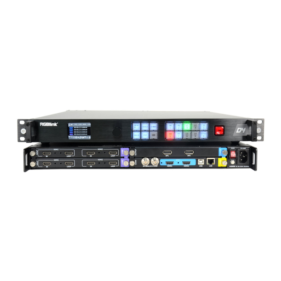
Page 8: Front Panel
1.2.1 Front Panel Button Instruction Number button 0~9, use for scale, crop, zoom and custom Input signal source button setting Show operation menu items Test pattern button Layer selection button Short cut button to open Effect menu Confirm and adjust OLED menu Scale button Menu and back button Dimmer button... - Page 9 Genlock Lock MENU Mini Delay Mode Mirror Flip Not Remote Presentation Remote Rotate Spit Standard Temperature Unlock HDCP 2.X, UHD, 4K, HDR10, HLG, HDMI 2.0, DP 1.2, HDMI 2.1, DP 1.4, 6G SDI, 12G SDI, H.264, H.265 User Manual...
-
Page 10: Back Panel
1.2.2 Back Panel Chassis Module Structure 2 input module slots, support DP1.2,12G SDI HDMI 2.0 and 3G SDI Communication connectors including:1 Input Module ( The bottom slot LAN port, and 1 USB-B support HDR) standard HDMI output (HDR Power switch Supported) 1 output module slot, support 4K HDMI,DP 12G SDI and 3G SDI output... -
Page 11: Dimension
1.2.3 Dimension Following is the dimension of D4 for your reference: HDCP 2.X, UHD, 4K, HDR10, HLG, HDMI 2.0, DP 1.2, HDMI 2.1, DP 1.4, 6G SDI, 12G SDI, H.264, H.265 User Manual... -
Page 12: Chapter 2 Install Your Product
2.2 Plug in Main Power Connect IEC cable to device and plug into wall socket. Turn on power at wall socket. 2.3 Turn on Your D4 The device will enter to the boot interface, and OLED display will show as below, completing initialization before loading last settings and input/output configuration. -
Page 13: Chapter 3 Use Your Product
Chapter 3 Use Your Product 3.1 Use the MENU Button Push【MENU】button to enter main menu. Turn the knob to select corresponding menu item. The symbol >indicate that the item is selected. Push the knob or【OK】button to confirm the operation. The symbol* means the selected item is under editing state, ready to be set or checked The operation diagram is as follows:... -
Page 14: Menu Operation
3.3 Menu Operation Use the menu system for convenient and intuitive operation. D4 TST display shows the menu items. The TST display will show the default state when the menu is not in use, or the operation has timed out. Using the 【MENU】 button and rotary knob in the front panel, the TST display will show the corresponding menus according to user selections. - Page 15 2. Output Format: users can rotate the knob to choose desired output resolution from 60 types of normal resolutions up to 4096x2160@60 Output Format 3840x2160@50 3. Custom Format In the first page of MENU items, there is Customize Format available. Input >>...
- Page 16 4. Genlock: users can turn on or off Genlock and set Genlock Format. >Genlock Genlock Format 3840x2160@50 Users can turn the knob to choose Genlock Y or Frame lock. 5. Split: It is provided for users to do splitting on One Machine or Multi Machine. One or Multi One or Multi One Machine...
- Page 17 6. Effects: users can set output image effects here.users can set output image effects here. To open up Effect menu, just press Effect button on the front panel. Layer Brightness >> Contrast >> Chroma >> Black&White Layer: Layer 1 or 2. Layer option is available under the system mode of Dual, Split and Mini Delay Under mode of Standard and Switch, there is no Layer in Effect menu Brightness: ranging from -1024 to 1024, users can not only adjust the overall brightness but also...
- Page 18 6 noise reduction made available.Each rang from 0 to 3. Horizontal NR Combining NR Vertical NR TemporalNR Block NR Mosquito NR Flip V: vertical mirror On or Off, Flip H: horizontal mirror, on or Off Reset:On or Off, select on to reset all above parameter. 7.
-
Page 19: Input Setting
3.3.2 Input Setting 1. Input Info: shows the input info of each input port as input resolution, Color Space(RGB/YUV) and HDR. Input 1: No Input No HDR 2.Sizing Adjust: 1)adjust input size and position. H Size 1408 V Size H Pos V Pos Reset Size H Size+H Pos ≦... -
Page 20: Transition Setting
Customize Format: *3840x2160@60 Width<4096 3.3.3 Transition Setting 1. Mode: to select the transition mode for for switching. Cut or Fade available. 2. Duration: the duration time of transition. If under Fade Mode, duration time range from 0.0-2.0s Mode Duration Invalid 3.3.4 Test Pattern 1. -
Page 21: Save&Load
3.3.5 Save&Load Save To >> Load From >> 1. Save To: save settings made above to Save_1,2,3...16,use knob to choose SAVE 1,2,3...16 Save To > Save_1 2. Load From:load saved settings from Save_1,2,3...16,use knob to choose SAVE 1,2,3...16 Load From >... - Page 22 Standard Mode Both output channels are duplicated offering the same output as program and monitor. PIP’s are available in this mode with PiP/layer count dependent on output resolution and layer arrangement. Example: 4K input scaled across a 4K output with 4K PIP source overlaid 2.2 Switch (Preview) Mode Both outputs are set to the same resolution, whether 2K or 4K, with one channel serving as program (PGM), and the other channel as preset preview (PST) for full seamless alpha switching...
- Page 23 2.4 Independent (Dual 4K) Mode Each of output channels separately configured for image, resolution, scale and other attributes Example: Two separate inputs to two separate outputs, each at different resolution 2.5 Split Mode Output channels are utilised to split or splice input source(s) to create large seamless and fully synchronized video wall.
- Page 24 3. Lanauge 语言:to switch language English or Chinese. User can also press MENU+SCALE for 3S to switch language. 4. Ethernet IP Address >> Subnet Mask >> Gateway >> Users can manually set IP address, Subnet mask, Gateway by rotating the knob if needed. 5.
-
Page 25: Factory Reset
Fan Speed Adjust fan speed from 1% to 99% by rotating the knob. 3.3.7 Factory Reset Factory Reset YES<OK>,NO<MENU> 3.3.8 Tech Support show the contact info of RGBlink Sales Hotline: 4008-592-114 After-Sale Service: 4008-592-315 sales@rgblink.com HDCP 2.X, UHD, 4K, HDR10, HLG, HDMI 2.0, DP 1.2, HDMI 2.1, DP 1.4, 6G SDI, 12G SDI, H.264, H.265... -
Page 26: Shortcut Button Operation
3.4 Shortcut Button Operation 3.4.1 Scale Button Press Scale Button on the front panel to enter scale setting menu under different system mode as follows: Under Standard/Switch mode: Reset H Size V Size H/V Size H POS V Pos Under Presentation mode: Layer Layer A V Size... -
Page 27: Pip Button
Presentation Layer: Choose from layer A /B/ C/ D Template: BG+3 1,BG+3 2, Square Channel: choose from CH.1, CH.2 H SIZE: set the horizontal pixels of output image V SIZE: set the vertical pixels of output image H/V Size: Set the scale ratio by putting in the horizontal width, the vertical height will be auto adjusted according to the ratio of new width/old width.e.g. -
Page 28: Dimmer Button
3.4.3 DIMMER Button Press Dimmer Button on the front panel to set Dimmer value or long pressing Dimmer button the value can immediately skip from 0 to 128. >Dimmer Dimmer range:0-128 3.4.4 HDR Button Press HDR button on the front panel to activate HDR feature: >Input Port Port3 In HDR Support... -
Page 29: Chapter 4 Ordering Codes
Chapter 4 Ordering Codes 4.1 Product 120-0004-01-0 4.2 Options 4.2.1 Input Options 191-0004-01-0 Dual DP 1.2 Input Module Dual HDMI 2.0 Input Module 191-0004-02-0 191-0004-03-0 3G SDI Input Module 191-0004-04-0 12G SDI Input Module 4.2.2 Output Options 191-0004-21-0 Dual DP 1.2 Output Module User Manual... -
Page 30: Chapter 5 Support
Chapter 5 Support 5.1 Contact Us User Manual... -
Page 31: Chapter 6 Appendix
Chapter 6 Appendix 6.1 Specification DP1.2 Input Module Connector Appearance Numbers of Input Connector DisplayPort Type Supported Standard Input Resolutions VESA 720p@25/30/50/60 | 1080i@50/59.94/60 | 1080p@23.98/24/25/29.97/30/50/59.94/60 | 2160p@30/50/60 SMPTE 1920×1200@60 | 2560×1600@60 | 3840×2160@23.98/24/25/29.97/30/50/60 | 4096×2160@50/60 HDMI 2.0 Input Module Connector Appearance Numbers of Input... - Page 32 3G SDI Input Module Connector Appearance Numbers of Input 2 (2 Input, 2Loop) Connector Type Supported Standard SMPTE 425M (Level A ) | SMPTE 424M | SMPTE 292M | SMPTE 259M-C | DVB-ASI Support Resolution SMPTE 720P@50/59.94/60 | 1080i@59.94/60 | 1080P@23.98/24/25/29.97/30/50/60 | 1080psf@23.98/24/25/29.97/30 3G SDI In supports Level A only (does not support Level B)
- Page 33 1920×1200@60 | 2048×1152@60 | 2560×812@60 | 2560×816@60 | 2560×1600@60 | 3840×1080@60| 3840×2160@23.98/24/25/29.97/30/50/60 | 4096×2160@50/60 HDMI 2.0 Output (Standard) Connector Appearance Numbers of Output Connector Type HDMI-A Supported Standard HDMI 2.0 Supported SMPTE 720p@25/30/50/60 | Resolution 1080p@23.98/24/25/29.97/30/50/59.94/60 | 1080i@50/59.94/60 | 2160p@30/50/60 VESA 800×600@60 | 1024×768@60 | 1280×768@60 | 1280×800@60 |1280×1024@60 | 1360×768@60 |...
-
Page 34: Terms & Definitions
6.2 Terms & Definitions ●RCA:Connector used primarily in consumer AV equipment for both audio and video. The RCA connector was developed by the Radio Corporation of America. ●BNC: Stands for Bayonet Neill-Concelman. A cable connector used extensively in television (named for its inventors). - Page 35 ●HDMI : High Definition Multimedia Interface: An interface used for the transmission of uncompressed high definition video, up to 8 channels of audio, and control signals, over a single cable. ●HDMI 1.3: released on June 22 2006, and increased the maximum TMDS clock to 340 MHz (10.2 Gbit/s). Support resolution 1920 ×...
- Page 36 communication links and for applications where high power must be transmitted. ●Single-mode Fiber: Fiber that support a single mode are called single-mode fibers. Single-mode fibers are used for most communication links longer than 1,000 meters (3,300 ft). ●SFP : small form-factor pluggable , is a compact, hot-pluggable network interface module used for both telecommunication and data communications applications.
- Page 37 USB 2.0 USB 3.0 3.1&3.2 ●NTSC : The colour video standard used in North America and some other parts of the world created by the National Television Standards Committee in the 1950s. NTSC utilizes an interlaced video signals. ●PAL: Phase Alternate Line. A television standard in which the phase of the colour carrier is alternated from line to line.
- Page 38 ●SDVoE: Software Defined Video over Ethernet (SDVoE) is a method for transmission, distribution and management AV signals using a TCP/IP Ethernet infrastructure for transport with low latency. SDVoE is commonly used in integration applications. ●Dante AV: The Dante protocol was developed for and widely adopted in audio systems for the transmission of uncompressed digital audio on IP based networks.
- Page 39 applications. Built on the DMX512 data format, ArtNet enables multiple “universes” of DMX512 to be transmitted using ethernet networks for transport. ●MIDI: MIDI is the abbreviation of Musical Instrument Digital Interface. As the name indicates the protocol was developed for communication between electronical musical instruments and latterly computers.
- Page 40 composite video signal. This serves as a colour synchronizing signal to establish a frequency and phase reference for the Chroma signal. Colour burst is 3.58 MHz for NTSC and 4.43 MHz for PAL. ●Colour Bars: A standard test pattern of several basic colours (white, yellow, cyan, green, magenta, red, blue, and black) as a reference for system alignment and testing.
-
Page 41: Revision History
6.3 Revision History The table below lists the changes to the Video Processor User Manual. Format Time ECO# Description Principal V1.0 2019-5-13 0000# Release Fanny V1.1 2019-6-6 0001# Revise Fanny V1.2 2020-03-20 0002# ● Add System mode,UI , button color 2. Fanny ●...
Need help?
Do you have a question about the D4 and is the answer not in the manual?
Questions and answers