Table of Contents
Advertisement
Quick Links
Advertisement
Table of Contents

Related Manuals for RGBlink FLEX 8


Summary of Contents for RGBlink FLEX 8
- Page 1 FLEX 8 USER MANUAL Article No: RGB-RD-UM-FLEX 8 E001 Revision No: V1.1...
-
Page 2: Table Of Contents
Chapter 3 Use Your Product........................12 3.1 Matrix Panel Operation........................12 3.1.1 MENU Operation........................12 3.1.2 Button Operation........................14 3.2 XPOSE Control FLEX 8........................16 3.2.1 Install Software........................16 3.2.3 Login to the Software......................19 3.2.4 Connect to Software......................20 3.2.5 Output Setting........................22 Output setting..........................23... -
Page 3: Declarations
30 days after the transfer of risks. In the event of justified notice of compliant, RGBlink can repair the fault or provide a replacement at its own discretion within an appropriate period. If this measure proves to be impossible or unsuccessful, the purchaser can demand a reduction in the purchase price or cancellation of the contract. -
Page 4: Operators Safety Summary
Installation Safety Summary Safety Precautions For all FLEX 8 installation procedures, please observe the following important safety and handling rules to avoid damage to yourself and the equipment. To protect users from electric shock, ensure that the chassis connects to earth via the ground wire provided in the AC power Cord. - Page 5 The AC Socket-outlet should be installed near the equipment and be easily accessible. Unpacking and Inspection Before opening FLEX 8 shipping box, inspect it for damage. If you find any damage, notify the shipping carrier immediately for all claims adjustments. As you open the box, compare its contents against the packing slip.
-
Page 6: Chapter 1 Your Product
Chapter 1 Your Product 1.1 In the Box AC Power HDMI-DVI Cable CAT5 Cable DVI To RCA Cord Connector Antistatic Bag DVI To VGA Connector Note: AC Power Cable supplied as standard according to destination market. User Manual FLEX 8... -
Page 7: Product Overview
1.2 Product Overview FLEX 8 is a matrix capable to distribute any input signal to any output signal through its consistent modular capability to control up to 16 different inputs and 16 different outputs independently. Different devices can be connected in each output and input. It supports HDMI, DVI, SDI, USB and HDBaseT input and output signals, as well as DP output. -
Page 8: Basic Front Panel
Power Indicator Lan Indicator Light up when device power on Lights up when LAN Keep lighting when device is communication occurs working Serial Port Indicator Infrared Indicator Lights up when serial communication occurs User Manual FLEX 8... -
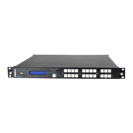
Page 9: Matrix Front Panel
1.2.2 Matrix Front Panel Matrix front panel fit for FLEX 8 with matrix feature (with EXT4F-OM installed) Panel Instruction USB INTERFACE To upgrade POWER BUTTON the device Turn on/off button. Indicator lights when the device is powered up or in standby state. -
Page 10: Back Panel
Supports input signals including HDMI, DVI, SDI, USB and HDBaseT. Output Interface Output Card Slots Supports output signals including HDMI, DVI, SDI, USB, HDBaseT and DP. Control Interface Communication Ports RS232&LAN Connect to XPOSE software Power Connection Power Socket-IEC User Manual FLEX 8... -
Page 11: Dimension
1.2.4 Dimension Following is the dimension of FLEX 8for your reference: User Manual FLEX 8... -
Page 12: Chapter 2 Install Your Product
Connect signals to the product (ensure all devices are powered off first). Tighten connector screws/locks where provided.Connect to XPOSE software by CAT5 cable. RGBlink provides a network cable for this connection, as a standard accessories. Please check in the package for this cable. -
Page 13: Chapter 3 Use Your Product
Shows : the status of each input to output and the LCD screen shows the exact info, as following example In→Out, 1→1 2→2 3→3 4→4 And the software version, serial number and IP address of the device. FLEX 8 User Manual... - Page 14 The LCD shows info as follow: FRONT PANEL LOCKED PRESS MENU 3S UNLOCK After front panel is unlocked, MENU button light goes out. WORK TIME Show the total boot times and working time up to now. BOOT TIMES: TOTAL TIME:650MIN FLEX 8 User Manual...
-
Page 15: Button Operation
I : 6 6 6 6 6 6 6 6 Press button ALL again, all lights go out except button 1 in OUT. SAVE If the IN→OUT (matrix) setting need to be saved, press button SAVE , LCD will show FLEX 8 User Manual... - Page 16 In stand by mode, press POWER for 3S, all buttons flashes one by one immediately and LCD shows RGBLINK FLEX 8 5S later, the device goes back to work and in the status before stand by. FLEX 8 User Manual...
-
Page 17: Xpose Control Flex 8
3.2 XPOSE Control FLEX 8 3.2.1 Install Software Minimum Requirements Windows Operation System Windows 7/8/10 Processor 1GHz/32 bit or 64 bit processor Memory Hard Disk 16Gb Graphics 128Mb/DirectX9 Display 1280X720 Operation System Mac OS Processor 1.0GHz+ Memory 512M+ Hard Disk... - Page 18 , it will pop-up the Installer Language box, select the language, for example, select “English”, and click “OK” to confirm. It will pop-up the installer box, and click “Next” to install, as follows: 2. Select “Browse...” to select the XPOSE software install location and click install: FLEX 8 User Manual...
- Page 19 3. User should get the rights in “Roles Management” when install the software to disk C if the system is Windows 7 or above. 4. Click “Finish” and is ready to run the XPOSE management software: FLEX 8 User Manual...
-
Page 20: Login To The Software
Admin, and defaultly there is no password. Select “FLEX 16”, select language “English” and enter the software by clicking “Login”. 2. If user wants to change the language to Chinese, click the drop down arrow after “Language” and select “中文”, then click “Login” to enter the software. FLEX 8 User Manual... -
Page 21: Connect To Software
Settings and Log out. In the following parts come with the detail. 3.2.4 Connect to Software Connect the remote controller PC which runs XPOSE to Flex 8 by the network cable In The Box.Click search to find the device as follows:... - Page 22 After Sync, enter the following interface. Close the current interface, just click the X on the right top corner and enter the main menu interface. FLEX 8 User Manual...
-
Page 23: Output Setting
3.2.5 Output Setting Click Output setting and enter the interface as below: FLEX 8 User Manual... -
Page 24: Output Setting
Note: avoid using following resolution 720×480i@60Hz and 720×576i@50Hz (not supported on all output modules, except via adapter through DVI module connected to EXT 4F-OM matrix output ext interface ), 2560×816@60Hz and 2048×1152@60Hz (not supported on DVI and HDMI output) . FLEX 8 User Manual... -
Page 25: De Setting
Board Type: select EXT-6 (EXT4F-OS) or EXT-4 (EXT4F-OM) based on the real installation of the device. Out/In: Output setting or Input setting Port:Port1-Port 8 to choose Output Type:DVI or HDMI Color Range:Image or Video Bits:8bit Brightness:0-128 FLEX 8 User Manual... -
Page 26: Operation Mode
There are 2 working modes, including the Matrix mode and Splitting Mode. Click the “Operation Mode”, and enter the interface as follows: Matrix Mode and Splitting Mode are included in operation mode, specific as follows: Matrix Mode Click the “Matrix Mode”, and enter to the interface as follows: FLEX 8 User Manual... - Page 27 In→Out 1. Choose input source from the signal source list 2. Drag the signal souce to Signal 3. Click Take 4. The display will show the input source correspondingly as the following show: FLEX 8 User Manual...
- Page 28 For FLEX 8 with matrix front panel, users can use XPOSE or front panel panel to control the device. For FLEX 8 with basic front panel, users can only use XPOSE to control. 1 IN-All Out Choose one input source from the signal source list...
- Page 29 Output Card Click each output port, users can set output resolution of each port Choose Advance, scale and crop setting can be done. FLEX 8 User Manual...
-
Page 30: Splitting Mode
Click the “Splitting Mode”, and pop-up window as follow: To do quick splitting, users can choose signal from signal list and drag it to the window. Drag the border of the layer to cover all the monitors. FLEX 8 User Manual... - Page 31 Input Setting The signal list is shown as follows: It displays the input module type, the quantity of inputs and input format. Click”... “afer the format of input for the following settings: FLEX 8 User Manual...
- Page 32 Set Input Property: Right click the input and select “Input Property”, it will enter to the interface as follows: Scale: Set the X, Y, width and height. Crop: Crop the left, top, width and height. Display Mode: Select “Live” or “Freeze”. FLEX 8 User Manual...
- Page 33 Test Pattern: Slide the Test Pattern switch to enable or disable the function. For USB input setting there is USB player setting select “USB Player”, it will enter to the USB Player interface, including movie and picture, default play the USB picture. FLEX 8 User Manual...
- Page 34 USB picture player setting: Can select play in order, random, single cycle and all cycle, and switch to pre or next, pause or play. DVI module of FLEX 8 is compatible with VGA,CVBS, YPbPr signals via adapter , therefore for other signal such as VGA input, users need to choose VGA in DVI input...
- Page 35 Reset outputs: User can reset outputs by clicking the shortcut on the right side of the interface. Swap outputs: User can swap outputs by clicking the shortcut on the right side of the interface, as shown in the figure below. FLEX 8 User Manual...
- Page 36 1, and adjust the size. Click this monitor, then press button C and don’t let go, select the monitor that will set, the size of the selected monitor will be changed to the same size of monitor 1, as shown in the figure below: FLEX 8 User Manual...
- Page 37 1. Auto Adaptive 2. Adjust the proportion of output area on the interface window automatically. 3. Up Down Left Right Arrow to move the position 4. + - to adjust the size FLEX 8 User Manual...
- Page 38 Choose Board 1-4 Color Choose: Signal Souce, Color Bar, Pure Color Set TP OK FLEX 8 User Manual...
- Page 39 ”. The selected layer will pasted to the bank. Adaptive: If scale the output area to a large area, click the adaptive shortcut “ ” on the right side of the interface, the output area will be return to the best position. FLEX 8 User Manual...
- Page 40 The take interface is shown as the figure below: Set the transition time, and the adjustment range is 0~10S. Slide the black out switch to enable or disable the black function. Auto take on is the FLEX 8 User Manual...
- Page 41 The special display project or LED display application would like to require special resolution settings to meet the requirement. Select the suitable input port to customize the EDID. As shown in the figure below: Loop Click the loop shortcut “ ”, and pop-up window as follows: Timing Loop FLEX 8 User Manual...
- Page 42 “ON”, the exact time to play the bank can be set. Times Loop Slide the loop switch to enable or disable the times loop function for the bank. If select “ON”, the exact length of time to play the bank can be set. FLEX 8 User Manual...
- Page 43 (Save Script) or chose Offline Saved to save saved bank to local computer Offline Saved as follows: Offline Saved Choose offline saved, it will pop window with saved banks. Choose the bank to be save and click OK, bank will be saved to local computer. FLEX 8 User Manual...
- Page 44 Click the factory reset shortcut “ ” to reset to factory settings. Factory reset is to go back to the factory initial setting of each IN-OUT. Page Set Click the page set shortcut “ ” to load and save pages. FLEX 8 User Manual...
- Page 45 Grey page indicate this page has been used, a setting has been saved in this page. Load Page Green page indicated that there is a saved available to load. Shortcut Keys Click the shortcut “ ”, and pop-up window as follows: FLEX 8 User Manual...
- Page 46 Use shortcut key to operate fast and easily. FLEX 8 User Manual...
-
Page 47: System Settings
Click “Connect Setting”: Select ”COM Port” and “Baud Rate”, click the drop down arrow after them, and click “OK”. Setting the device connecting ways: Serial Connect, Ethernet Connect and Search by this configuration. After setting ”COM Port” and “Baud Rate”, pop-up window as follows: FLEX 8 User Manual... - Page 48 This is usually used if one computer control some devices or remote control. It takes effect after reboot the software if change IP through network. System Information Click “System Information”, and pop-up window as follows: FLEX 8 User Manual...
- Page 49 Display the device version information. Including Model Number, Serial Number, IP Address, firmware version, etc. Factory Reset Click “Factory Reset”, and pop-up window as follows: Click “OK” or “Cancel” to confirm the reset. FLEX 8 User Manual...
-
Page 50: Logout
To disable Auto Fan cotrol setting, slide OFF to ON, Set Fan Speed at 0~100 3.2.8 Logout Click “Logout” to exit the XPOSE sorftware, and pop up window as follows: Click “cancel” or “OK” to confirm User also can be click the right corner red button to exit software directly FLEX 8 User Manual... -
Page 51: Chapter 4 Ordering Codes
Chapter 4 Ordering Codes Product 710-0008-01-0 FLEX 8 Modules 4.2.1 Input 190-0001-10-2 Single USB2.0 Input/Backup Input Module 190-0001-07-2 Single 3G SDI In/Loop Module 190-0001-13-2 Single HDMI Input Module 190-0001-04-2 Single DVI Input Module 190-0002-29-0 Single HDBaseT Input Module 980-0004-01-0 Single EXT4F-IM Input Interface 4.2.2 Output... -
Page 52: Chapter 5 Support
Chapter 5 Support FLEX 8 User Manual... -
Page 53: Chapter 6 Appendix
800×600@60 | 1024×768@60 | 1280×720@50/59.94/60 | 1280×800@60 | 1280×960@60 | 1280×1024@60 | 1400×1050@60 | 1600×1200@60 | 1920×1080@23.98/24/25/29.97/30/50/59.94/60 DVI Composite Input Module Connector Appearance Numbers of Connectors Connectors DVI-I (Compatile with VGA,CVBS,YPbPr via Adapter) Supported Standard UXGA FLEX 8 User Manual... - Page 54 .DAT | .MPG 1920×1080@ 20Mbps | .MPEG MPEG2 .MPG 1920×1080@ 20Mbps MPEG4 .AVI | .MP4 DVIX | XVID 1920×1080@ 20Mbps | .3GP | .ASF RM | RMVB .RM | .RMVB RV8 | RV9 | 1280×720@3 10Mbps FLEX 8 User Manual...
- Page 55 Full Range DP Output Module Connector Appearance Numbers of Connectors Connectors DisplayPort Supported Standard DP1.1 SMPTE 720p@50/59.94/60 | 1080i@50/59.94/60 | Supported 1080p@50/59.94/60 Resolution VESA 800x600@60 | 1024x768@60 | 1280x720@50/59.94/60 | 1280x800@60 | 1280x960@60 | 1280x1024@60 | FLEX 8 User Manual...
- Page 56 1280×768@60 | 1280×800@60 |1280×1024@60/75/85 | 1360×768@60 | 1366×768@60 |1400×900@60 |1600×1050@60 | 1600×1200@60 |1680×1050@60 | 1920×1080@60 | 1920×1200@60 |2048×1152@60 | 2560 ×816@60 DVI Output Module Connector Appearance Numbers of Connectors Connectors DVI-I (Compatile with VGA,CVBS,YPbPr via Adapter) Supported Standard FLEX 8 User Manual...
- Page 57 Power Supply AC 90-264V 50/60Hz 1.8A Max Max Power °C-4 °C Working Environment Relativity Humidity 10% –85 % RH Weight 4.5 kg Dimensions 484mm × 449mm × 45mm Product Warranty 3 years parts and labor warranty FLEX 8 User Manual...
-
Page 58: Terms & Definitions
In the computer, the most commonly used color bars are two rows of reversed color bars. “Color burst”: In color TV systems, a burst of subcarrier frequency located on the back porch of the composite video signal. This serves as a color synchronizing FLEX 8 User Manual... - Page 59 10 bit depth and 4:2:2 color quantization over a single coaxial cable with a data rate of 1.485 Gbit/second. Multiple video resolutions exists including progressive 1280x720 and interlaced 1920x1080 resolution. Up to 32 audio signals are carried in the ancillary data. FLEX 8 User Manual...
- Page 60 The standard specifies component connection standards with regard to the computer interface. It is also called RS-232-C, which is the third version of the RS-232 standard, and is functionally identical to the CCITT V.24 FLEX 8 User Manual...
- Page 61 The number of devices being designed for USB continues to grow, from keyboards, mice, and printers to scanners, digital cameras, and ZIP drives. “VESA”: Video Electronics Standards Association. A nonprofit number organization FLEX 8 User Manual...
- Page 62 4. It has a pixel by line resolution of 640×480 with a color palette of 16 bits and 256,000 colors. “YCrCb”: Used to describe the color space for interlaced component video. “YPbPr”: Used to describe the color space for progressive-scan (non-interlaced) component video. FLEX 8 User Manual...
-
Page 63: Revision History
6.3 Revision History The table below lists the changes to the User Manual of FLEX 8. Format Time ECO# Description Personnel V1.0 2019-4-29 0000# Release Fanny V1.1 2019-9-26 0001# Update Fanny FLEX 8 User Manual...
Need help?
Do you have a question about the FLEX 8 and is the answer not in the manual?
Questions and answers