Table of Contents
Advertisement
Advertisement
Chapters
Table of Contents

Related Manuals for Beckhoff CX5120


Summary of Contents for Beckhoff CX5120
- Page 1 Manual CX51x0 Embedded-PC Version: Date: 2018-01-25...
-
Page 3: Table Of Contents
Setting up the audio interface (N020) ................ 40 Windows Embedded Standard 7 P.................... 41 7.2.1 Identification of the Ethernet interfaces (X000, X001) ............. 41 7.2.2 Enabling jumbo frames .................... 42 7.2.3 Set NIC Teaming...................... 43 7.2.4 Restoring the Beckhoff real-time driver................ 45 CX51x0 Version: 1.9... - Page 4 Enabling jumbo frames .................... 47 7.3.3 Set NIC Teaming...................... 48 7.3.4 Restoring the Beckhoff real-time driver................ 50 Beckhoff Device Manager...................... 51 7.4.1 Starting the Beckhoff Device Manager ................ 51 7.4.2 Enabling a remote display.................... 52 TwinCAT ............................ 53 7.5.1 Tree view.......................... 53 7.5.2 Searching for target systems ................... 54 7.5.3...
-
Page 5: Notes On The Documentation
EP0851348, US6167425 with corresponding applications or registrations in various other countries. ® EtherCAT is registered trademark and patented technology, licensed by Beckhoff Automation GmbH, Germany Copyright © Beckhoff Automation GmbH & Co. KG, Germany. The reproduction, distribution and utilization of this document as well as the communication of its contents to others without express authorization are prohibited. -
Page 6: Explanation Of Symbols
Notes on the documentation Explanation of symbols The following symbols with corresponding warnings or explanatory text are used in the documentation. Read and follow the warnings. Symbols that warn of personal injury: Serious risk of injury Note this warning. Hazard with high risk of death or serious injury. DANGER Risk of injury Note this warning. -
Page 7: Related Documents
Please refer to the corresponding documentation for important information and notes regarding operation of the CX51x0 Embedded PCs in potentially explosive atmospheres. In particular, read and follow the sections on safety contained in this document: http://www.beckhoff.de Document name Notes on using the CX51x0 in potentially explosive atmospheres. -
Page 8: For Your Safety
Beckhoff Automation GmbH & Co. In addition, the following actions are excluded from the liability of Beckhoff Automation GmbH & Co. KG: • Failure to comply with this documentation. -
Page 9: Staff Qualification
For your safety Staff qualification All operations involving Beckhoff software and hardware may only be carried out by qualified personnel with knowledge of control and automation engineering. The qualified personnel must have knowledge of the administration of the Embedded PC and the associated network. - Page 10 • The sensitivity of a PC against malicious software increases with the number of installed and active software. • Uninstall or disable unnecessary software. Further information about the safe handling of networks and software can be found in the Beckhoff Information System: http://infosys.beckhoff.de...
-
Page 11: Transport And Storage
Embedded PC must be protected from • mechanical stress and • use the original packaging. Table 1: Dimensions and weight of the individual modules. CX5120 CX5130 CX5140 Dimensions (W x H x D) 123 mm x 100 mm x 91... -
Page 12: Product Overview
Product overview Product overview The CX5100 product family comprises three Embedded PCs, which differ in terms of processor type, RAM and housing size. The CX51x0 Embedded PC is a full-fledged PC with the following basic configuration: • CFast card slot, •... -
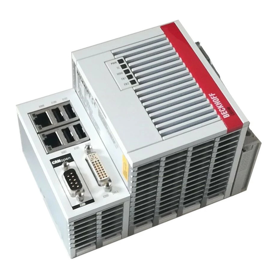
Page 13: Configuration Of The Cx51X0 Embedded Pc
Product overview Configuration of the CX51x0 Embedded PC Fig. 1: Example: CX5140 Embedded PC. Table 3: Legend for the configuration. Component Description Space for interfaces such as RS232, EtherCAT, CANopen or Optional interface [} 21] others. (X300). The optional interface must be ordered ex factory and cannot be retrofitted retrospectively. -
Page 14: Name Plate
Product overview Name plate The CX51x0 Embedded PC features a name plate on the left-hand side of the housing. Fig. 2: CX51x0 name plate. Table 4: Legend for the name plate. Description UL approval with prescribed information on power supply, fuse, temperature and cable cross-sections. -
Page 15: Types
TwinCAT version of the Embedded PC. Fig. 3: Nomenclature for the CX51x0 Embedded PC. The Embedded PCs CX5120, CX5130 and CX5140 are available with the following software options: Table 5: CX51x0, ordering information for software. Modul... -
Page 16: Architecture Overview
Product overview Architecture overview The Embedded PCs of the CX51x0 family all have the same architecture. This is described below. The CX51x0 Embedded PCs are based on the Intel Atom microarchitecture, which was developed by Intel. The following CPUs are used: ®... - Page 17 Product overview The interfaces (USB, DVI, and LAN) are standard interfaces. Devices that meet the corresponding standard can be connected to and operated at these interfaces. A VGA monitor can be connected to the DVI-I interface with an adapter. ® Intel i210 Gigabit Ethernet controllers are used as network controllers.
-
Page 18: Description Of The Interfaces
Description of the interfaces Description of the interfaces USB (X100, X101, X102, X103) Fig. 4: USB interfaces (X100, X101, X102, X103). The Embedded PC has four independent USB interfaces for connecting keyboards, mice, touchscreens and other input or data storage devices. Fig. 5: USB interface, pin numbering. -
Page 19: Ethernet Rj45 (X000, X001)
Description of the interfaces Ethernet RJ45 (X000, X001) The two Ethernet interfaces are independent; no switch is integrated. The independent Ethernet interfaces can be configured in different ways. In delivery state the Ethernet interfaces (X000, X001) are configured for EtherCAT communication. Note that an additional switch is required for a line topology. -
Page 20: Dvi-I (X200)
The DVI-I interface (X200) transfers digital data and is suitable for connection to digital or analog monitors. The resolution at the display or the Beckhoff Control Panel depends on the distance from the display device. The maximum distance is 5 m. Beckhoff offers various Panels with an integrated “DVI extension”. These make a cable length of up to 50 meters possible. -
Page 21: Optional Interfaces
N010 interface (DVI-D interface) is used, the first DVI-I interface can be operated either in VGA mode or in DVI mode. The resolution at the display or the Beckhoff Control Panel depends on the distance from the display device. The maximum distance is 5 m. Beckhoff offers various Panels with an integrated “DVI extension”. -
Page 22: Displayport (N011)
Description of the interfaces 5.4.2 DisplayPort (N011) The DisplayPort transfers image and audio signal at the same time and is therefore suitable for connecting panels or monitors to the Embedded PC. Fig. 10: DisplayPort X300. Version 1.1a of the DisplayPort (DisplayPort++) is installed on the Embedded PC. Adapters from DisplayPort to DVI-D or DisplayPort to HDMI can be used to connect monitors without DisplayPort to the Embedded PC. -
Page 23: Audio Interface (N020)
Description of the interfaces 5.4.3 Audio interface (N020) Two inputs are available: "LINE IN" (X300) and "MIC IN" (X301). The "LINE OUT" interface (X302) is intended for audio signal output. The 3.5 mm sockets are designed for jack plugs. It can also be used for connecting headphones with a maximum output of 200 mW. -
Page 24: Rs232 (N030)
Description of the interfaces 5.4.4 RS232 (N030) The optional N030 interface provides an RS232 interface (X300). The RS232 interface is implemented on a 9-pin D-sub connector. Fig. 14: RS232 interface X300 with pin numbering. The maximum baud rate on both channels is 115 kbit. The interface parameters are set via the operating system or from the PLC program. -
Page 25: Rs422/Rs485 (N031)
Description of the interfaces 5.4.5 RS422/RS485 (N031) The optional N031 interface provides an RS422 or RS485 interface (X300). The interface is implemented on a 9-pin D-sub connector. Fig. 15: RS485 interface X300 with pin numbering. The maximum baud rate on both channels is 115 kbit. The interface parameters are set via the operating system or from the PLC program. - Page 26 Description of the interfaces • SetupComm • SetCommBreak • ClearCommBreak • EscapeCommFunction (no support for parameters SETBREAK and CLR-BREAK) • IOCTL_SERIAL_XOFF_COUNTER • IOCTL_SERIAL_LSRMST_INSERT • IOCTL_SERIAL_SET_BREAK_ON • IOCTL_SERIAL_SET_BREAK_OFF Version: 1.9 CX51x0...
-
Page 27: Ethercat Slave (B110)
Receive + connected reserved RD - Receive - connected reserved For the optional EtherCAT slave interface (B110), documentation with further information is available for download from the Beckhoff website: https://www.beckhoff.de/german/download/epc.htm?id=71003127100362 Document name CXxxx0-B110 optional interface EtherCAT slave. CX51x0 Version: 1.9... -
Page 28: Profibus (X310)
PROFIBUS line D sub B red Pin 3 A green Pin 8 For the optional PROFIBUS interface (x310), documentation with further information is available for download from the Beckhoff website: https://www.beckhoff.de/german/download/epc.htm?id=71003127100362 Document name CXxxx0-x310 optional Profibus interface. Version: 1.9 CX51x0... -
Page 29: Canopen (X510)
CAN ground (internally connected to pin 3) CAN high (CAN+) not used not used For the optional CANopen interface (x510), documentation with further information is available for download from the Beckhoff website: https://www.beckhoff.de/german/download/epc.htm?id=71003127100362 Document name CXxxx0-x510 optional CANopen interface. CX51x0... -
Page 30: Profinet Rt (X930)
Description of the interfaces 5.4.9 PROFINET RT (x930) Fig. 20: PROFINET RT interface X300. Fig. 21: PROFINET RT LAN interface, pin numbering. Table 23: PROFINET RT interface, pin assignment. Signal Description TD + Transmit + TD - Transmit - RD + Receive + connected reserved RD -... -
Page 31: Commissioning
Commissioning Commissioning Assembly 6.1.1 Note the permissible installation positions Increased heat generation The Embedded PC may overheat if the installation position is incorrect or the minimum dis- tances are not adhered to. Note The Embedded PC may only be operated at ambient temperatures of up to 60 °C. Ensure adequate ventilation. -
Page 32: Fig. 23 Cx51X0 Embedded Pc, Invalid Installation Positions
Commissioning Incorrect installation positions Fig. 23: CX51x0 Embedded PC, invalid installation positions. Version: 1.9 CX51x0... -
Page 33: Attaching On Mounting Rail
Commissioning 6.1.2 Attaching on mounting rail The housing is designed such that the Embedded PC can be pushed against the mounting rail and latched onto it. Requirements: • Mounting rail of type TS35/7.5 or TS35/15 according to DIN EN 60715. Secure the Embedded PC on the mounting rail as follows: 1. -
Page 34: Microsd Card Installation And Removal
Note fail, resulting in data loss. Only use industrial MicroSD cards provided by Beckhoff. The MicroSD card slot is intended for a MicroSD card. Data and further programs can be stored here, or Windows Embedded Compact 7 can be installed instead. -
Page 35: Cfast Card Installation And Removal
A CFast card is a non-volatile memory. Data to be retained in the event of a power failure should be saved on the CFast card. The CFast cards supplied by Beckhoff are industrial cards with an increased number of write cycles and an extended temperature range (+85 °C). -
Page 36: Installing Passive Ethercat Terminals
Commissioning 6.1.5 Installing passive EtherCAT Terminals Incorrectly installed passive EtherCAT Terminals The E-bus signal between an Embedded PC and the EtherCAT Terminals can be impaired due to incorrectly installed passive EtherCAT Terminals. Note Passive EtherCAT Terminals should not be installed directly on the power supply unit. EtherCAT Terminals that do not take part in active data exchange are referred to as passive terminals. -
Page 37: Connecting The Power Supply
Commissioning Connecting the power supply Damage to the Embedded PCs The Embedded PCs may be damaged during wiring. The cables for the power supply should only be connected in de-energized state. Note The power supply terminals require an external voltage source, which provides 24 V DC (-15% / +20%). The power supply terminal must provide 4 A at 24 V, in order to ensure the operation of the Embedded PCs in all situations. -
Page 38: Table 25 Required Wire Cross-Sections And Strip Lengths
Commissioning Compliance with UL requirements: • The Embedded PCs must not be connected to unlimited voltage sources. • Embedded PCs may only be supplied from a 24 V DC voltage source. The voltage source must be insulated and protected with a fuse of maximum 4 A (corresponding to UL248). -
Page 39: Switching On
Commissioning Switching on Please ensure that the Embedded PC is fully configured before switching on the Embedded PC. Switch on the Embedded PC as follows: 1. Ensure that all extension, system and fieldbus modules are connected correctly. 2. Check whether the right CX2100 power supply unit and the right installation position were selected. 3. -
Page 40: Configuration
Configuration Windows Embedded Compact 7 7.1.1 Setting up the audio interface (N020) Under Windows Embedded Compact 7, the Beckhoff CX configuration tool can be used for the audio settings. Requirements: • Embedded PC with audio interface. • Windows Embedded Compact 7. -
Page 41: Windows Embedded Standard 7 P
Configuration Windows Embedded Standard 7 P 7.2.1 Identification of the Ethernet interfaces (X000, X001) Network and Sharing Center In the Network and Sharing Center the Ethernet interfaces (X000, X001) of the CX51x0 Embedded PC are identified as follows as standard: •... -
Page 42: Enabling Jumbo Frames
Requirements: • The original Intel® driver can be downloaded from https://downloadcenter.intel.com. • Install the original Intel® driver. Note that this will delete the real-time capable driver from Beckhoff. • Check whether the peripheral devices support jumbo frames. Jumbo frames are activated as follows: 1. -
Page 43: Set Nic Teaming
• The original Intel® driver can be downloaded from https://downloadcenter.intel.com. • Install the original Intel® driver for the Network Interface Card. Note that this will delete the real-time capable driver from Beckhoff. NIC Teaming is set as follows: 1. Under Start > Control Panel > Hardware and Sound click on Device Manager. - Page 44 Configuration 5. Under Select a team type select the option Adapter Fault Tolerance 6. Click on Next to complete the installation. ð You have successful set NIC Teaming for your Ethernet interfaces. Further settings can be specified or changed under the Settings tab. Version: 1.9 CX51x0...
-
Page 45: Restoring The Beckhoff Real-Time Driver
The installation dialog appears and shows the compatible Ethernet interfaces under Compatible devices. 2. Select the Ethernet interfaces for which you wish to restore the Beckhoff real-time driver and click on Install. ð The Beckhoff real-time driver is installed. The Ethernet interfaces with installed Beckhoff real-time driver are shown under Installed and ready to use devices (real-time capable). -
Page 46: Windows 10 Iot Enterprise Ltsb
Configuration Windows 10 IoT Enterprise LTSB 7.3.1 Identification of the Ethernet interfaces (X000, X001) Network and Sharing Center In the Network and Sharing Center the Ethernet interfaces (X000, X001) of the CX51x0 Embedded PC are identified as follows as standard: •... -
Page 47: Enabling Jumbo Frames
Requirements: • The original Intel® driver can be downloaded from https://downloadcenter.intel.com. • Install the original Intel® driver. Note that this will delete the real-time capable driver from Beckhoff. • Check whether the peripheral devices support jumbo frames. Jumbo frames are activated as follows: 1. -
Page 48: Set Nic Teaming
• The original Intel® driver can be downloaded from https://downloadcenter.intel.com. • Install the original Intel® driver for the Network Interface Card. Note that this will delete the real-time capable driver from Beckhoff. NIC Teaming is set as follows: 1. Under Start > Control Panel > Hardware and Sound click on Device Manager. - Page 49 Configuration 5. Under Select a team type select the option Adapter Fault Tolerance 6. Click on Next to complete the installation. ð You have successful set NIC Teaming for your Ethernet interfaces. Further settings can be specified or changed under the Settings tab. CX51x0 Version: 1.9...
-
Page 50: Restoring The Beckhoff Real-Time Driver
The installation dialog appears and shows the compatible Ethernet interfaces under Compatible devices. 2. Select the Ethernet interfaces for which you wish to restore the Beckhoff real-time driver and click on Install. ð The Beckhoff real-time driver is installed. The Ethernet interfaces with installed Beckhoff real-time driver are shown under Installed and ready to use devices (real-time capable). -
Page 51: Beckhoff Device Manager
Beckhoff Device Manager 7.4.1 Starting the Beckhoff Device Manager The Beckhoff Device Manager can be used to configure an Embedded PC with a web browser via a host PC. The Beckhoff Device Manager can also be used for diagnostic purposes. Requirements: •... -
Page 52: Enabling A Remote Display
1. Enter the IP address or the host name of the Embedded PC in a web browser on the host PC. Example with IP address: http://169.254.136.237/config Example with host name: http://CX-16C2B8/config 2. In the authentication window enter the user name and the password for the Beckhoff Device Manager. The default settings are: User name: Webguest Password: 1 3. -
Page 53: Twincat
Configuration TwinCAT 7.5.1 Tree view The Tree View chapter can be used as an example for creating a project without actual hardware. All devices and components of an Embedded PCs must be added manually in TwinCAT 3. The smallest possible configuration of the CX51x0 Embedded PC is created as follows in the tree view under TwinCAT 3: Fig. 31: CX51x0 Embedded PC in the tree view of TwinCAT 3, with attached EtherCAT Terminals (left) or Bus Terminals (right). -
Page 54: Searching For Target Systems
Configuration 7.5.2 Searching for target systems Before you can work with the devices, you must connect your local computer to the target device. Then you can search for devices with the help of the IP address or the host name. The local PC and the target devices must be connected to the same network or directly to each other via an Ethernet cable. - Page 55 Configuration Enter the user name and password for the CX in the User Name and Password fields and click OK. The following information is set as standard in CX devices: User name: Administrator Password: 1 6. If you do not wish to search for any further devices, click on Close to close the Add Route Dialog. The new device is displayed in the Choose Target System window.
-
Page 56: Adding An Embedded Pc
Configuration 7.5.3 Adding an Embedded PC With this step you can add an Embedded PC in TwinCAT and then configure it. Prerequisites for this step: • A scanned and selected target device. Add the Embedded PC as follows: 1. Start TwinCAT and open an empty project. 2. -
Page 57: Configure The Serial Interface (N03X)
Configuration 7.5.4 Configure the serial interface (N03x) This chapter explains how to configure a CX51x0 with serial interface (N03x) in TwinCAT. The procedure for commissioning the CX51x0-N03x with serial interface under TwinCAT differs from that for other Embedded PCs. In order to avoid configuration errors, the procedure for adding and configuring the CX51x0 in TwinCAT is described below. - Page 58 Configuration 5. Under the Serial Port tab, select the option PCI/PCIe Device. The serial interface of the CX51x0 is shown under Port:. If the option Onboard/ISA device is already selected, the option PCI/PCIe device is grayed out and cannot be selected. The option PCI/PCIe device can be re-enabled as follows: 6.
-
Page 59: Configuring Ethercat Cable Redundancy
Requirements: • For TwinCAT 2 you have to install and license the supplement TS622x | TwinCAT EtherCAT Redundancy on the Embedded PC: http://www.beckhoff.de/forms/twincat3/warenkorb.aspx?lg=de&title=TS622x-EtherCAT- Redundancy&version=1.0.2 • In TwinCAT 3 the supplement is already included and only has to be licensed. • Hardware wired as EtherCAT ring (see Fig.: Smallest possible configuration for EtherCAT cable redundancy) and added in TwinCAT. - Page 60 Configuration Configure EtherCAT cable redundancy as follows: 1. In the tree view click on the EtherCAT master. 2. Click on the EtherCAT tab, then Advanced Settings. 3. Click on Redundancy in the tree structure on the left. 4. Click on the option Second adapter, followed by the Search button. Version: 1.9 CX51x0...
-
Page 61: Using A Hardware Watchdog
Configuration 5. Select the appropriate LAN connection according to your cabling at the Embedded PC. 6. Confirm the settings with OK. ð You have successfully configured cable redundancy. Under the Online tab the EtherCAT slaves are displayed, for which cable redundancy was configured. Under State the state of the individual EtherCAT slaves is displayed. - Page 62 Configuration Unwanted restart The watchdog restarts the Embedded PC as soon as the time set for nWatchdogTimeS elapses. Attention Be aware of this behavior and disable the watchdog if you use breakpoints, carry out a PLC reset or an overall reset, stop TwinCAT, switch to config mode or activate the configuration. Requirements: •...
-
Page 63: 1-Second Ups (Persistent Data)
• Subsequently you can check the validity of the variables and monitor whether the persistent variables are loaded without error (see: Checking the validity of the variables [} 70]). Sample project: https://infosys.beckhoff.com/content/1033/CX51x0_HW/Resources/pro/1937303563.pro. Components Version TwinCAT on the development PC and on the control system TwinCAT 2.11R3 Build 2047 (or higher) -
Page 64: Bios Settings
1-second UPS (persistent data) BIOS settings The CX51x0 family features a built-in capacitive one-second UPS. It ensures a safe storage of the persistent application data on the Compact Flash card. Up to 1 MB of persistent data can be saved. The UPS can be switched on and off via the BIOS. Under the menu: Advanced ->... - Page 65 TwinCAT offers special function blocks for integrating the S-UPS into a PLC program. These are described below. From TwinCAT 2.11R3 Build 2247 or TwinCAT 3.1 Build 4018 the required library is integrated in the installation. For older versions the library: https://infosys.beckhoff.com/content/1033/CX51x0_HW/Resources/rar/1941420683.rar has to be copied into the TwinCAT library directory. CX51x0...
-
Page 66: Windows Write Filter
Check the configuration of the UWF if you have made changes to the exception list. Fig. 34: UWF exception list under TwinCAT 3 By default, the persistent data are stored under \TwinCAT\3.1\Boot in TwinCAT 3. The UWF can be configured via the Beckhoff Unified Write Filter Manager. Version: 1.9 CX51x0... -
Page 67: Table 29 Block Modes
1-second UPS (persistent data) FB_S_UPS_CX51x0 Loss of data The 1-second UPS switches the mainboard off as soon as the capacitors have discharged. If other applications or the PLC are keeping other data open or are writing to them, data Note may be corrupted or lost. - Page 68 1-second UPS (persistent data) tTimeout: Timeout for the execution of the quick shutdown. eUpsMode: The eUpsMode defines whether persistent data are to be written and whether a quick shutdown is to be performed. Standard value is eSUPS_WrPersistData_Shutdown, i.e. with writing of the persistent data and then quick shutdown.
-
Page 69: Mode And Status Of The Function Block
1-second UPS (persistent data) Mode and status of the function block E_S_UPS_Mode With the mode selected in the function block you can specify what should happen in the case of a power failure. eSUPS_WrPersistData_Shutdown: Writing of persistent data and then a QuickShutdown eSUPS_WrPersistData_NoShutdown: Only writing of the persistent data (no QuickShutdown) eSUPS_ImmediateShutdown: Only QuickShutdown (no writing of persistent data) eSUPS_CheckPowerStatus: Only check status (neither writing of persistent data nor a QuickShutdown) E_S_UPS_State The internal state of the function block can be read with E_S_UPS_State. eSUPS_PowerOK: in all modes: Power supply is OK eSUPS_PowerFailure: ... -
Page 70: Checking The Validity Of The Variables
1-second UPS (persistent data) Checking the validity of the variables For TwinCAT 2 the implicit structure Systeminfotype.bootDataFlags can be read in order to determine the validity of the persistent data (see: SYSTEMINFOTYPE [} 70]). For TwinCAT 3 the implicit variables PlcAppSystemInfo.BootDataLoaded and PlcAppSystemInfo.OldBootData are available for determining the validity of the persistent data (see: PlcAppSystemInfo [} 72]). - Page 71 A registry setting can be used to determine whether the backup file is deleted or used. The backup file is used by default (setting 0). If the backup file is to be deleted, the value of "ClearInvalidRetainData" or "ClearInvalidPersistentData" must be set to 1 in the registry under: [HKEY_LOCAL_MACHINE\SOFTWARE\Beckhoff\TwinCAT\Plc] "ClearInvalidRetainData"=dword:00000000 "ClearInvalidPersistentData"=dword:00000000 the value of "ClearInvalidRetainData"...
-
Page 72: Plcappsysteminfo
1-second UPS (persistent data) 8.5.2 PlcAppSystemInfo Each PLC provides a global instance of this type named '_AppInfo'. The corresponding namespace is 'TwinCAT_SystemInfoVarList'. For example this has to be added inside a library. TYPE PlcAppSystemInfo STRUCT ObjId : OTCID; TaskCnt : UDINT; OnlineChangeCnt : UDINT; Flags : DWORD; AdsPort : UINT; BootDataLoaded : BOOL; OldBootData : BOOL;... -
Page 73: Error Handling And Diagnostics
Error handling and diagnostics Error handling and diagnostics Diagnostic LEDs Display Meaning Power supply The power LED lights green if the device is connected to a power supply unit and the unit is switched on. The S-UPS is activated (violet). Bootloader is started and runs without errors (The colors red and yellow light up for one... -
Page 74: Power Supply Terminal Leds In K-Bus Mode
Error handling and diagnostics Power supply terminal LEDs in K-bus mode The power supply unit checks the connected Bus Terminals for errors. The red LED "K-bus ERR" is off if no error is present. The red LED "K-bus ERR" flashes if Bus Terminal errors are present. Display Meaning Us 24 V... -
Page 75: Table 31 K-Bus Err Led, Fault Description And Troubleshooting
Error handling and diagnostics Table 31: K-BUS ERR LED, fault description and troubleshooting. Error code Error code argu- Description Remedy ment Persistent, EMC problems. • Check power supply for undervoltage continuous or overvoltage peaks. flashing • Implement EMC measures. • If a K-bus error is present, it can be localized by a restart of the power supply (by switching it off and then on again) -
Page 76: Table 32 Description Of The State Variable Values
Error handling and diagnostics Fig. 35: Status variable for error handling and diagnostics under TwinCAT. If the value is "0", the K-bus operates synchronous and without error. If the value is <> "0" there may be a fault, or it may only be an indication that the K-bus cycle is longer than the task. In which case it would no longer be synchronous with the task. -
Page 77: Power Supply Terminal Leds In K-Bus Mode
Error handling and diagnostics Power supply terminal LEDs in K-bus mode The power supply unit checks the connected EtherCAT Terminals. The "L/A" LED is lit in E-bus mode. The "L/A" LED flashes during data transfer. Display Meaning Us 24 V Power supply for basic CPU module. -
Page 78: Faults
6. Any components / software used The quickest response will come from support / service in your country. Therefore please contact your regional contact. For details please refer to our website at www.beckhoff.de or ask your distribution partner. Version: 1.9... -
Page 79: Care And Maintenance
Only use original batteries and ensure that the positive and negative poles are inserted cor- Attention rectly. The battery must be replaced every 5 years. Spare batteries can be ordered from Beckhoff Service. A battery of type CR2032 from Sanyo or Panasonic is used for the Embedded PC. Table 33: Technical data of the battery. -
Page 80: Decommissioning
Decommissioning Decommissioning 11.1 Removing cables Electrical voltage Having the power supply switched on during the disassembly may damage the device. Switch off the power supply during the disassembly. Note Cabling Make a note of the wiring configuration, if you wish to restore it with another device. Note Before dismantling the Embedded PC, shut down the Embedded PC and switch off the power supply. -
Page 81: Dismantling The Embedded Pc
Decommissioning 11.2 Dismantling the Embedded PC This chapter explains how to dismantle the Embedded PC and remove it from the mounting rail. Requirements: • All cables were removed from the Embedded PC. Dismantle the Embedded PC as follows: 1. Release the DIN rail mounting by pushing the latches outwards with a screwdriver. 2. -
Page 82: Technical Data
Technical data Technical data Table 34: Technical data, dimensions and weights. CX5120 CX5130 CX5140 Dimensions (W x H x D) 123 mm x 100 mm x 91 142 mm x 100 mm x 91 mm Weight approx. 975 g approx. 1095 g approx. -
Page 83: Table 37 Technical Data, Environmental Conditions
15 g, 11 ms according to EN 60068-2-27 EMC immunity according to EN 61000-6-2 Electromagnetic emission according to EN 61000-6-4 Protection class IP 20 Table 38: Technical data, graphic specifications. Technical data CX5120 CX5130 CX5140 ® ® ® Processor graphics Intel HD Graphics... -
Page 84: Appendix
Appendix Appendix 13.1 Accessories Table 41: CFast cards Order number Description CX2900-0028 4 GB CFast card, SLC flash, extended temperature range CX2900-0030 8 GB CFast card, SLC flash, extended temperature range CX2900-0032 16 GB CFast card, SLC flash, extended temperature range CX2900-0034 32 GB CFast card, SLC flash, extended temperature range CX2900-0036... -
Page 85: Certifications
All products of the Embedded PC family are CE, UL and EAC certified. Since the product family is continuously developed further, we are unable to provide a full listing here. The current list of certified products can be found at www.beckhoff.com. FCC Approvals for the United States of America... -
Page 86: Support And Service
Beckhoff's branch offices and representatives Please contact your Beckhoff branch office or representative for local support and service on Beckhoff products! The addresses of Beckhoff's branch offices and representatives round the world can be found on her internet pages: http://www.beckhoff.com You will also find further documentation for Beckhoff components there. -
Page 87: List Of Tables
Table 24 Legend for the connection example..................... Table 25 Required wire cross-sections and strip lengths ................Table 26 Access data for the Beckhoff Device Manager on delivery............Table 27 Legend for the tree view......................Table 28 Cable redundancy, hardware for sample configuration............... -
Page 88: List Of Figures
List of figures List of figures Fig. 1 Example: CX5140 Embedded PC....................Fig. 2 CX51x0 name plate........................Fig. 3 Nomenclature for the CX51x0 Embedded PC................Fig. 4 USB interfaces (X100, X101, X102, X103).................. Fig. 5 USB interface, pin numbering...................... Fig.
Need help?
Do you have a question about the CX5120 and is the answer not in the manual?
Questions and answers