Beckhoff C5 Series Installation And Operating Instructions Manual

Beckhoff C5 Series Installation And Operating Instructions Manual

19 inch rack mount industrial pc
Table of Contents

Advertisement

Quick Links

Installation and Operating instructions for
19 Inch Rack Mount Industrial PC
C5102 from -0060
Version: 4
Date:
2020-04-24

Advertisement

Table of Contents
loading

Summary of Contents for Beckhoff C5 Series

  • Page 1 Installation and Operating instructions for 19 Inch Rack Mount Industrial PC C5102 from -0060 Version: 4 Date: 2020-04-24...
  • Page 3: Table Of Contents

    Table of contents Table of contents 1 Foreword Notes on the Documentation 1.1.1 Liability Conditions 1.1.2 Trademarks 1.1.3 Patent Pending 1.1.4 Copyright 1.1.5 State at Delivery 1.1.6 Delivery conditions Description of safety symbols Basic safety measures Operator’s obligation to exercise diligence 1.4.1 National regulations 1.4.2...
  • Page 4 5 Troubleshooting 6 Assembly dimensions 7 Technical Data 8 Appendix Beckhoff Support and Service 8.1.1 Beckhoff branches and partner companies 8.1.2 Beckhoff company headquarters Approvals for USA and Canada FCC Approvals for the United States of America FCC Approval for Canada...
  • Page 5: Foreword

    Modifications to hardware or software configurations other than those described in the documentation are not permitted, and nullify the liability of Beckhoff Automation GmbH & Co. KG. 1.1.6 Delivery conditions In addition, the general delivery conditions of the company Beckhoff Automation GmbH & Co. KG apply. C5102...
  • Page 6: Description Of Safety Symbols

    Foreword 1.2 Description of safety symbols The following safety symbols are used in this operating manual. They are intended to alert the reader to the associated safety instructions. Acute risk of injury! If you do not adhere the safety advise adjoining this symbol, there is immediate danger to life and health of individuals! DANGER Risk of injury!
  • Page 7: Basic Safety Measures

    Foreword 1.3 Basic safety measures Before the Industrial PC is switched off, software that is running must be properly closed. Otherwise it is possible that data on the storage medium is lost. Please read the section Switching the Industrial PC on and off.
  • Page 8: Operator's Obligation To Exercise Diligence

    Foreword 1.4 Operator’s obligation to exercise diligence The operator must ensure that • the product is only used as intended (see chapter Product Description) • the product is in a sound condition and in working order during operation • the product is operated, maintained and repaired only by suitably qualified and authorized personnel •...
  • Page 9: Product Description

    Product Description 2 Product Description
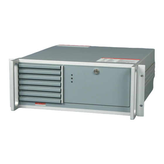
 2.1 Product overview C5102 | 19-inch slide-in Industrial PC The Industrial PCs of the series C5xxx are designed for 19-inch rack installation. They are equipped with maximum performance class components and are ideally suited for machine construction and plant engineering applications, for example with the TwinCAT automation software.
  • Page 10: Appropriate Use

    Product Description 2.2 Appropriate Use The C5102 Industrial PC has been designed as a rack mount PC for fitting into 19-inch racks used in machine and plant engineering applications. Risk of explosion! The Industrial PC must not be used where there is a risk of explosion. Danger 2.3 Opening the Housing Only trained persons may open the Industrial PC housing!
  • Page 11 Product Description In order to open the PC housing, remove the 4 fastening screws at the side of the housing cover (see arrows) using a cross-head screwdriver. The cover of the housing can then be lifted up, providing access to the hard drive, processor, memory, plug-in cards and battery. Removing the card holder Remove the 2 fastening screws of the card holder (see arrows) using a cross-head screwdriver.
  • Page 12: Access To The Battery

    If the Industrial PC is used in an environment where the air is particularly dirty, the fan's filter mat should be examined at regular intervals to see how dirty it is, and should be exchanged, if necessary, for an original Beckhoff filter mat (item number C9900-Z213, filter mat for C510x, 10 per pack). Front view showing the filter drawer Access to the filter mat is obtained behind the front flap.
  • Page 13: Interfaces From C5102-0060

    Product Description 2.6 Interfaces from C5102-0060 2.6.1 PS/2 connections (X103, X104) The upper PS/2 connector (X104) allows a PS/2 mouse to be used, while a PC keyboard can be connected to the lower PS/2 connector (X103). 2.6.2 USB interfaces USB1 – USB4 (X108, X109, X110, X111) The four USB interfaces (X108 –...
  • Page 14: Interfaces Behind The Front Flap

    Product Description 2.7 Interfaces behind the front flap Interfaces behind the front flap Reset-pushbutton: The reset pushbutton (1) allows to reboot the PC. Keyboard-Lock: The pushbutton KB-LK (2) locks the keyboard. LEDs: The LED Power (3) indicates correct power supply. The LED HDD (4) indicates HDD access.
  • Page 15: Installation

    4. Please keep the associated paperwork. It contains important information for handling the unit. 5. Check the contents for visible shipping damage. 6. If you notice any shipping damage or inconsistencies between the contents and your order, you should notify Beckhoff Service. C5102...
  • Page 16: Installation Of The Pc In The Control Cabinet

    Installation 3.2 Installation of the PC in the control cabinet The C5102 Industrial PC has been designed as a rack mount PC for fitting into 19-inch racks used in machine and plant engineering applications. The ambient conditions specified for operation must be observed (see chapter Technical Data).
  • Page 17: Power Supply Of The Industrial Pc

    Installation 3.3 Power supply of the Industrial PC The Industrial PC is fitted with a 100-240 V/ 3 A max., 50-60 Hz full range power supply unit (with the option of an uninterruptible power supply UPS). 3.3.1 Current carrying capacity of the 100-240 V power supply unit Output voltages from the 100-240 V power supply unit Current loading maximum +3,3 V...
  • Page 18: Power Supply With

    The new Beckhoff power supply technology approach addresses this problem and now offers the user the option of switching the PC off without the need for using the battery, thereby reducing the load on the battery.
  • Page 19: Current Carrying Capacity Of The 24 V Power Supply Unit

    Installation Control Panel with a display dimension up to 19 inches. This enables a power failure to be visualized and displayed to the user. Once the PC has shut down, the UPS output is switched off. For a detailed functional description please refer to section Connecting Power Supply. 3.4.2 Current carrying capacity of the 24 V power supply unit Output voltages from the 24 V power supply unit Current loading maximum...
  • Page 20: Fitting The Cables

    Installation Pin assignment external wiring Pin assignment for connecting the power switch X102 1 2 3 Function Power-Status PC-ON Power Supply +pole 3.4.4 Fitting the cables Fit the cables for the power supply of the Industrial PC, the connection of the battery pack as well as the connection of the power-switch in accordance with the wiring diagram, using the included material for assembling the connectors.
  • Page 21: Connecting Power Supply

    Installation 3.4.5 Connecting Power Supply The external wiring consists of the connection of the power supply, the battery pack (optional) and the connection of customized components for shutting down the PC. Cable Cross Sections For the connection of the power supply, wiring with a cable-cross-section of 1.5 mm must be used.
  • Page 22: Wiring Diagram

    Installation 3.4.6 Wiring diagram Wiring according to the wiring diagram (the circuit of PC_ON and Power-Status is symbolical): Wiring diagram external switch and power supply Connection of the Battery Pack and UPS Output Connection of the Battery Pack and UPS Output only in combination with integrated UPS (order option).
  • Page 23: Connecting The Industrial Pc

    Installation 3.5 Connecting the Industrial PC The mains plug must be disconnected The power supply plug must be withdrawn! Attention Please read the documentation for the external devices prior to connecting them! During thunderstorms, plug connector must neither be inserted nor removed! When disconnecting a plug connector, always handle it at the plug.
  • Page 24: Operating Instructions

    Operating Instructions 4 Operating Instructions 4.1 Switching the Industrial PC on and off 4.1.1 Switch on The Industrial PC has its own mains switch. The Industrial PC will start when the main switch switched 4.1.2 Shutting down and switching off When the plant is switched off, or when it is disconnected from its power supply, the Industrial PC will be switched off.
  • Page 25: Servicing And Maintenance

    Operating Instructions 4.2 Servicing and maintenance 4.2.1 Cleaning of the Industrial PC Disconnect power supply Switch off the Industrial PC and all connected devices, and disconnect the Industrial PC from the power supply. DANGER The device can be cleaned with a soft, damp cleaning cloth. Do not use any aggressive cleaning materials, thinners, scouring material or hard objects that could cause scratches.
  • Page 26: Troubleshooting

    Procedure Nothing happens after the Industrial No power supply to the Industrial Check power supply cable PC has been switched on Call Beckhoff Service Other cause The Industrial PC does not boot CD in drive Remove CD and press any...
  • Page 27: Assembly Dimensions

    Assembly dimensions 6 Assembly dimensions Industrial PC C5102 Notice mounting orientation The assembly of the unit must take place with the orientation diagrammed here. Attention All dimensions in mm. Front view Top view Side view C5102...
  • Page 28: Technical Data

    Technical Data 7 Technical Data Risk of explosion! Do not use the Industrial PC in areas of explosive hazard! Danger Product description C5102 Dimensions (B x H x T) 483 x 177 x 449 (+ 51 with handles) mm Weight 17.0 kg (basic configuration) Supply voltage 100 V...
  • Page 29: Appendix

    Please contact your Beckhoff branch office or partner company for local support and service on Beckhoff products! The contact addresses for your country can be found in the list of Beckhoff branches and partner companies: www.beckhoff.com. You will also find further documentation for Beckhoff components there.
  • Page 30: Approvals For Usa And Canada

    Appendix 8.2 Approvals for USA and Canada 8.3 FCC Approvals for the United States of America FCC: Federal Communications Commission Radio Frequency Interference Statement This equipment has been tested and found to comply with the limits for a Class A digital device, pursuant to Part 15 of the FCC Rules.

This manual is also suitable for:

C5102

Table of Contents