
Subscribe to Our Youtube Channel
Related Manuals for Beckhoff C6515


Summary of Contents for Beckhoff C6515
- Page 1 Installation and Operating instructions for Built-in Industrial PC C6515 Version: 1.1 Date: 2021-11-16...
-
Page 3: Table Of Contents
Unpacking Installation of the PC in the control cabinet Earthing measures Mounting of the Industrial PC Power Supply Connection Beckhoff power supply technology Pin assignment of the connector Fitting the cable Material for assembling the connectors Assembling the connectors Connecting Power Supply... - Page 4 Table of contents Troubleshooting Fault correction Beckhoff Support & Service Beckhoff branches and partner companies Beckhoff Headquarters Beckhoff Support Beckhoff Service Assembly dimensions Appendix Technical data Approvals FCC: Federal Communications Commission Radio Frequency Interference Statement FCC: Canadian Notice C6515...
-
Page 5: General Notes
© This documentation is copyrighted. Any reproduction or third party use of this publication, whether in whole or in part, without the written permission of Beckhoff Automation GmbH, is forbidden. Description of safety symbols The following safety symbols are used in this operating manual. They are intended to alert the reader to the associated safety instructions. -
Page 6: Basic Safety Measures
If metal objects such as screws or tools fall onto operating circuit boards. • If connecting cables internal to the PC are removed or inserted during operation. • If plug-in cards are removed or inserted when the PC is switched C6515... -
Page 7: Operator's Obligation To Exercise Diligence
Read the operating Every user of the Industrial PC must have read these operating instructions instructions. Software knowledge Every user must be familiar with any of the functions of the software installed on the PC that he can reach. C6515... -
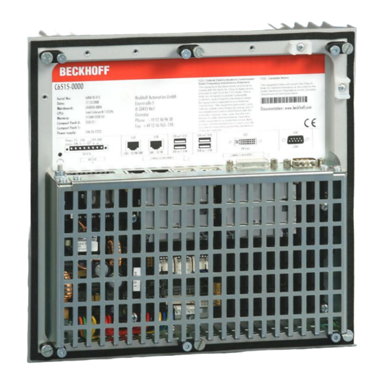
Page 8: Product Description
Product Description Appropriate Use The C6515 Industrial PC is designed for mounting in control cabinets or in the rear panel of a control or console housing for machine and plant engineering applications. The heat sink of the IPC is thereby fed to the outside through a suitable cut-out in the panel of the control cabinet. -
Page 9: Interfaces
There is a type plate on the top of the Industrial PC which provides information about the hardware configuration of the Industrial PC at the time it was supplied. Ground connection Ground connection stud bolt The Industrial PC is grounded via the stud bolt. C6515... -
Page 10: Installation Instructions
4. Please keep the associated paperwork. It contains important information for handling the unit. 5. Check the contents for visible shipping damage. 6. If you notice any shipping damage or inconsistencies between the contents and your order, you should notify Beckhoff Service. C6515... -
Page 11: Installation Of The Pc In The Control Cabinet
Installation Instructions Installation of the PC in the control cabinet The C6515 Industrial PC is designed for mounting in control cabinets for machine and plant engineering applications. The ambient conditions specified for operation must be observed (see chapter Technical data). -
Page 12: Mounting Of The Industrial Pc
Release clamping levers, Insert the Industrial PC into the cutout. Release the clamping levers with a No. 2.5 Allen key. folding them out Turn the clamping levers to the side through 90°, and retighten them. and retighten the screws. C6515... -
Page 13: Power Supply Connection
However, over time this reduces the service life of the battery. The new Beckhoff power supply technology approach addresses this problem and now offers the user the option of switching the PC off without the need for using the battery, thereby reducing the load on the battery. -
Page 14: Pin Assignment Of The Connector
8-pole plug connector . Function Pin assignment for connecting the switch, the Battery Pack (with UPS only) power supply and the 1 2 3 4 5 6 7 8 battery pack (optional) UPS+ (Output) 24 V DC Power Supply PC_ON Power-Status C6515... -
Page 15: Fitting The Cable
Tighten the lacing cord and pinch off the plastic strap. Fixing the upper part of the strain relief housing Fix the upper part of the strain relief housing by snapping it onto the lower part. C6515... -
Page 16: Connecting Power Supply
The maximum load is 2.0 A. • Once the PC has been de-energised via the UPS software, the UPS output is switched to 0 V. Any connected panel is thus switched off, and total discharge of the rechargeable battery is prevented. C6515... -
Page 17: Wiring Diagram
Wiring according to the wiring diagram (the circuit of PC_ON and Power- Status is symbolical): Wiring diagram external switch and power supply The battery pack can only be connected when the Industrial PC is provided with an integrated UPS (order option). Note C6515... -
Page 18: Connecting Devices
If a 24 V UPS is installed, the same type of rechargeable battery must be used. Warning Fastening the cables Fastening the cables The connecting cables of the Industrial PC can be fastened with lacing cords. Therefore the pictured clips are mounted at the housing (see arrow). C6515... -
Page 19: Operating Instructions
If the PC was ordered without operating system, you have to install the operating system and the driver software for any auxiliary hardware yourself. Please follow the instructions in the documentation for the operating system and the additional devices. C6515... -
Page 20: Maintenance
The device must be fully dismantled in order to dispose of it. The housing can be sent for metal recycling. Observe national Electronic parts such as disk drives and circuit boards must be disposed of electronics scrap in accordance with national electronics scrap regulations. regulations C6515... -
Page 21: Ups Software Components (Optional)
The driver software comes with a detailed help function. System The help files can be called up either directly from the configuration register by clicking the Help button, or under via Start > Programs > Beckhoff > UPS software components. C6515... -
Page 22: Troubleshooting
Nothing happens after the Industrial No power supply to the Industrial Check power supply cable. PC has been switched on Other cause. Call Beckhoff Service. The Industrial PC does not boot Setup settings are incorrect. Check the setup settings. fully Other cause. -
Page 23: Beckhoff Support & Service
Please contact your Beckhoff branch office or partner company for local support and service on Beckhoff products! The contact addresses for your country can be found in the list of Beckhoff branches and partner companies: www.beckhoff.com You will also find further documentation for Beckhoff components there. -
Page 24: Assembly Dimensions
Assembly dimensions Assembly dimensions The assembly of the unit must take place with the orientation diagrammed here. Warning Industrial PC C6515 All dimensions are in mm. rear view side view top view C6515... -
Page 25: Appendix
Appendix Appendix Technical data Industrial PC C6515 Dimensions (W x H x D): 240 x 230 x 81 mm Weight: 3.03 kg Do not use the PC in areas The Industrial PC may not be used in areas of explosive hazard.
Need help?
Do you have a question about the C6515 and is the answer not in the manual?
Questions and answers