
Related Manuals for Beckhoff C5210


Summary of Contents for Beckhoff C5210
- Page 1 Installation and Operating instructions for 19-inch slide-in Industrial PC C5210 Version: 1.3 Date: 2021-11-16...
-
Page 3: Table Of Contents
Access to the hard disks Access to the Control Elements 2.4.1 USB Interfaces (X112, X113) 2.4.2 ATX Push-button 2.4.3 Reset-button 2.4.4 Status LEDs Rear view of the C5210 2.5.1 100-240V Full Range Power Supply 2.5.2 Power Supply Interfaces 2.6.1 Serial interface (X102) 2.6.2 DVI (Digital Visual Interface) (X103) USB Interfaces (X104 –... - Page 4 Replacing the Battery on the Motherboard Emergency procedures Shutting down 4.4.1 Disposal 5 UPS Software Components (optional) Installation on the PC Help files 6 Troubleshooting 7 Assembly dimensions 8 Technical Data 9 Appendix Beckhoff Support and Service 9.1.1 Beckhoff branches and partner companies C5210...
- Page 5 Table of contents 9.1.2 Beckhoff company headquarters Approvals for USA and Canada FCC Approvals for the United States of America FCC Approval for Canada C5210...
-
Page 6: Foreword
Modifications to hardware or software configurations other than those described in the documentation are not permitted, and nullify the liability of Beckhoff Automation GmbH & Co.KG. 1.1.6 Delivery conditions In addition, the general delivery conditions of the company Beckhoff Automation GmbH & Co.KG apply. C5210... -
Page 7: Description Of Safety Symbols
CAUTION Hazard to devices and environment If you do not adhere the notice adjoining this symbol, there is obvious hazard to materials and environment. Attention Note or pointer This symbol indicates information that contributes to better understanding. Note C5210... -
Page 8: Basic Safety Measures
• if connecting cables internal to the PC are removed or inserted during operation. • if plug-in cards are removed or inserted when the PC is switched on. C5210... -
Page 9: Operator's Obligation To Exercise Diligence
1.4.3 Operator requirements Anyone who uses the Industrial PC must have read these operating instructions and must be familiar with all the functions of the software installed on the Industrial PC to which he has access. C5210... -
Page 10: Product Description
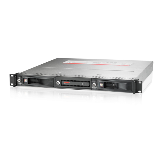
Front view C5210 The C5210 is fitted with two removable frames for hard disks (1) and (2). In condition of delivery one of the removable frames is fitted with a hard disk. Behind the flap (3) the control elements and two USB- interfaces are located. -
Page 11: Access To The Control Elements
The control elements are located behind a flap at the front side of the Industrial PC. After unlocking the flap with the key it can be folded down. You now have access to the control elements: Control elements ATX- Reset- status X113 X112 button button LEDs C5210... -
Page 12: Usb Interfaces (X112, X113)
TwinCAT RUN with Bus Error 2.5 Rear view of the C5210 The C5210 Industrial PC is fitted with a 100-240 V, 50-60 Hz full range power supply unit. Optional a 24 V power supply unit with UPS is available. -
Page 13: Dc Power Supply
Product Description 2.5.2 24V Power Supply Rear view C5210 with 24V power supply optional fieldbus power supply PCIe module slots battery interfaces 2.6 Interfaces Interfaces to the X104 X106 X102 X103 X108 X109 slide-in Industrial PC X105 X107 2.6.1 Serial interface (X102) The Industrial PC has one serial interface COM1 (X102), using the type RS232, which is brought to a 9 pin SUB-D plug connector. -
Page 14: Access To The Battery
The PCIe module slots are located behind the two cover caps in the area of the connectors of the Industrial PC. Access to the module slots For the installation of the plug in cards first remove the cross-head screws. The cover caps can now be removed and allow plugging in the plug in cards. C5210... -
Page 15: Installation
4. Please keep the associated paperwork. It contains important information for handling the unit. 5. Check the contents for visible shipping damage. If you notice any shipping damage or inconsistencies between the contents and your order, you should notify Beckhoff Service. C5210... -
Page 16: Installation Of The Pc Into The 19-Inch Rack
Installation 3.2 Installation of the PC into the 19-inch Rack The slide-in Industrial PC C5210 is designed for installation in a 19-inch rack (1 rack unit) in control cabinets for machine and plant engineering applications. The ambient conditions specified for operation must be observed (see chapter Technical Data). -
Page 17: Earthing Measures
Establish a low-impedance connection from the earthing point on the PC housing to the central earthing point on the control cabinet wall, in which the computer is being installed. The earthing connection is located right hand at the rear side of the Industrial PC when looking from behind. C5210... -
Page 18: 100-240 Vac Power Supply
Type SVT; one end terminates in NEMA 5-15P/-20P grounding-type attachment plug, other end in appliance coupler • Listed, Detachable, maximum 4.5 m (14.76 ft.) long; rated minimum 250 V, 10 A, Type SJT or Type SVT; one end terminates in NEMA 6-15P/-20P grounding-type attachment plug, other end in appliance coupler. C5210... -
Page 19: Vdc Power Supply (Optional)
The new Beckhoff power supply technology approach addresses this problem and now offers the user the option of switching the PC off without the need for using the battery, thereby reducing the load on the battery. -
Page 20: Pin Assignment Of The Connector For The Power Supply
Pin assignment of the connector Pin assignment for connecting the switch, the power supply and the battery pack (optional): 1 2 3 4 5 6 7 8 Function Battery Pack (with UPS only) UPS+ (Output) 24 V DC Power Supply PC_ON Power-Status C5210... -
Page 21: Fitting The Cable
Put the plug connector into that lower part of the strain relief housing. Tighten the lacing cord and pinch off the plastic strap. Fix the upper part of the strain relief housing by snapping it onto the lower part. C5210... -
Page 22: Connecting Power Supply
The 24 V DC connection at the UPS output is live even after a power failure. The maximum load is 1.4 A. • Once the PC has been de-energized via the UPS software, the UPS output is switched to 0 V. Any connected panel is thus switched off, and total discharge of the rechargeable battery is prevented. C5210... - Page 23 Wiring according to the wiring diagram (the circuit of PC_ON and Power-Status is symbolical): Wiring diagram external switch and power supply Connection of the Battery Pack and UPS Output Connection of the Battery Pack and UPS Output only in combination with integrated UPS (order option). Note C5210...
-
Page 24: Connecting The Industrial Pc
2. Insert the power supply cable that you have assembled into the Industrial PC's power supply socket. Then connect it to your external 24 V power supply. Use same type of rechargeable battery If a 24 V UPS is installed, the same type of rechargeable battery must be used. Attention C5210... -
Page 25: Operating Instructions
If the PC was ordered without operating system, you have to install the operating system and the driver software for any auxiliary hardware yourself. Please follow the instructions in the documentation for the operating system and the additional devices. C5210... -
Page 26: Servicing And Maintenance
Housing components (polycarbonate, polyamide (PA6.6)) are suitable for plastic recycling • Metal parts can be sent for metal recycling • Electronic parts such as disk drives and circuit boards must be disposed of in accordance with national electronics scrap regulations. C5210... -
Page 27: Ups Software Components (Optional)
Industrial PC. On delivery of the Beckhoff Industrial PC with operating system the software is already installed. Should the software not be installed on your PC, the drivers can be installed from the driver CD provided. -
Page 28: Troubleshooting
Procedure Nothing happens after the Industrial No power supply to the Industrial Check power supply cable PC has been switched on Call Beckhoff Service Other cause The Industrial PC does not boot Setup settings are incorrect Check the setup settings... -
Page 29: Assembly Dimensions
The assembly of the unit must take place with the orientation diagrammed here. Warning All dimensions are in mm. C5210 (basic configuration), view without assembly brackets Use Assembly Brackets The two provided assembly brackets are to retain the Industrial PC in the back area and have to be mounted at both sides. - Page 30 Assembly dimensions C5210, view with mounted assembly brackets C5210 with telescope rail Maedler-Accuride 2907 (Order option C9900-M712) C5210...
-
Page 31: Technical Data
Technical Data 8 Technical Data Risk of explosion! Do not use the Industrial PC in areas of explosive hazard! Danger Product name C5210 Dimensions (B x H x T) see chapter Assembly dimensions Weight 7.5 kg (basic configuration) 100 – 240 V... -
Page 32: Appendix
Please contact your Beckhoff branch office or partner company for local support and service on Beckhoff products! The contact addresses for your country can be found in the list of Beckhoff branches and partner companies: www.beckhoff.com. You will also find further documentation for Beckhoff components there. - Page 33 Technological changes to the device may cause the loss of the FCC approval. Note 9.4 FCC Approval for Canada FCC: Canadian Notice This equipment does not exceed the Class A limits for radiated emissions as described in the Radio Interference Regulations of the Canadian Department of Communications. C5210...
Need help?
Do you have a question about the C5210 and is the answer not in the manual?
Questions and answers