Table of Contents
Advertisement
Advertisement
Chapters
Table of Contents

Related Manuals for Beckhoff C6015


Summary of Contents for Beckhoff C6015
- Page 1 Manual | EN C6015 Industrial PC 8/11/2021 | Version: 2.7...
-
Page 3: Table Of Contents
Grounding of the Industrial PC .................. 26 4.3.2 Connecting cables and power supply ................ 27 Switching the Industrial PC on and off..................... 28 5 Beckhoff Device Manager ........................ 29 6 Decommissioning............................ 31 Disconnecting the power supply and cables ................... 31 Disassembly and disposal ....................... 32 7 Maintenance ............................. 34... - Page 4 Table of contents Version: 2.7 C6015...
-
Page 5: Notes On The Documentation
Copyright © Beckhoff Automation GmbH & Co. KG. Publication of this document on websites other than ours is prohibited. Offenders will be held liable for the payment of damages. All rights reserved in the event of the grant of a patent, utility model or design. -
Page 6: For Your Safety
Exclusion of liability Beckhoff shall not be liable in the event of non-compliance with this documentation and thus the use of the devices outside the documented operating conditions. Description of safety symbols The following safety symbols are used in these operating instructions. -
Page 7: Fundamental Safety Instructions
• the operating instructions are in good condition and complete, and always available for reference at the location where the products are used. C6015 Version: 2.7... -
Page 8: Product Overview
Product overview Product overview The C6015 Industrial PC supplements the Beckhoff entry-level products with an ultra-compact Industrial PC with high performance reserves for space-saving control cabinet installation. Thanks to the existing processors, the Industrial PC has sufficient performance reserves for the following applications, among others: •... -
Page 9: Structure
Product overview Structure Fig. 1: C6015_Structure – basic configuration Table 1: Key - C6015 structure Component Description Mounting plate Plate for mounting the Industrial PC over the narrow sides in the control cabinet Status LEDs Status display for power, hard disk, TwinCAT... -
Page 10: Interface Description
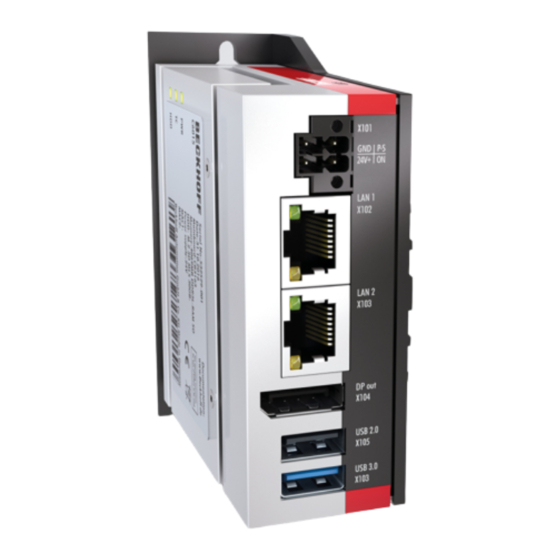
Product overview Interface description The basic version of the C6015 has the following interfaces: • Power supply (X101) • Ethernet RJ45 (X102, X103) • DisplayPort (X104) • USB (X105, X106) 3.2.1 Power supply The Industrial PC is supplied with a rated voltage of 24 V. The 2x2-pin voltage socket (X101) is used for connection to the power supply and the external wiring of the Industrial PC. -
Page 11: Ethernet Rj45
Product overview 3.2.2 Ethernet RJ45 The C6015 has two Gigabit LAN ports (X102, X103). The Ethernet standards 100Base-T and 1000Base-T enable connection of corresponding network components with data rates of 100/1000 Mbit/s. The required speed is selected automatically. The RJ45 connection technology with twisted-pair cables is used. The maximum length of the cable connection is 100 m. -
Page 12: Usb
USB interfaces. The following table shows the interface assignment based on the product variant: Table 5: USB interfaces depending on product variant Product variant USB interfaces C6015-0010 1x USB 2.0 (X105) 1x USB 3.0 (X106) C6015-0020 2x USB 3.0 (X105, X106) The two USB interfaces each supply up to 500 mA current and are electronically protected. -
Page 13: Displayport
The Industrial PC has a DisplayPort (X104) that enables connection of devices with DisplayPort. It facilitates transfer of image signals. In addition, DVI signals can be transferred via an adapter. Please order it from your Beckhoff sales team, quoting order identifier C9900-Z468 adapter cable DisplayPort to DVI, 40 cm. -
Page 14: Status Leds
• the status of the power controller • the TwinCAT status • the hard disk activity Fig. 6: C6015 Status LEDs 3.3.1 PWR LED The PWR (power) LED indicates the status of the power controller. The colors and flashing intervals have the following meanings: Table 8: Meaning of the PWR LED... -
Page 15: Hdd Led
The TC LED indicates the TwinCAT status. The colors and flashing intervals have the following meanings: Table 10: Meaning of the TC LED Color Flashing interval Meaning Green Steadily lit TwinCAT Run Mode Blue Steadily lit TwinCAT Config Mode Steadily lit TwinCAT Stop TwinCAT not started C6015 Version: 2.7... -
Page 16: Name Plate
The name plate provides information on the equipment fitted to the Industrial PC. xxxxxxxx xxxxxxxxxxxxx xxxxxxxxxxxxx Fig. 7: C6015_Name plate Table 11: Key - C6015 name plate Description Manufacturer, including address Model: The last four digits indicate the product variant Serial number (BTN) -
Page 17: Commissioning
5. Check the contents for visible shipping damage. 6. In case of discrepancies between the package contents and the order, or in case of transport damage, please inform Beckhoff Service (see Chapter 10.1 Service and support [} 41]). C6015 Version: 2.7... -
Page 18: Installation In The Control Cabinet
Commissioning Installation in the control cabinet The C6015 Industrial PC is designed for installation in control cabinets in machine and plant technology. Please observe the environmental conditions prescribed for the operation (see Chapter 9 Technical data [} 40]). Using different mounting plates, you can align the cable entry based on the application requirements. -
Page 19: Mounting Options
PC as required to align the connections in the control cabinet. You have the following mounting options, which are shown in Fig. 10: • Connections point upwards (A) • Connections point downwards (B) • Connections point to the right (C) • Connections point to the left (D) C6015 Version: 2.7... -
Page 20: Fig. 10: C6015 _Mounting Options For Mounting Plate 2
Commissioning Fig. 10: C6015 _Mounting options for mounting plate 2 With the optional mounting plate 3 with DIN rail adapter, you can mount the Industrial PC on the DIN rail in the control cabinet via the narrow sides. You have the following mounting options, which are shown in Fig. -
Page 21: Dimensions
Fig. 12 gives an example of the dimensions using the mounting option via the rear of the device with mounting plate 1. Fig. 12: C6015 _mounting plate rear panel Fig. 13 shows the dimensions using the mounting option with the connections pointing to the right with mounting plate 2 as an example. -
Page 22: Fig. 14 C6015 _Mounting Plate Din Rail Adapter
Commissioning 40.6 Fig. 14: C6015 _Mounting plate DIN rail adapter Version: 2.7 C6015... -
Page 23: Installation In The Control Cabinet
After you have drilled the holes for the fastening screws in the control cabinet, you can mount the Industrial PC in the control cabinet with mounting plates 1 or 2. Fig. 15: C6015 _Mounting plates for control cabinet installation To install the Industrial PC in the control cabinet, follow the steps below: 1. -
Page 24: Fig. 16 C6015_Din Rail Adapter For Control Cabinet Installation
3. Keep the device pressed upwards and also hook the upper side of the adapter into the DIN rail (C). ð You have successfully installed the Industrial PC on the DIN rail. Fig. 17: C6015_DIN rail adapter mounted Version: 2.7 C6015... -
Page 25: Connecting The Industrial Pc
Devices connected to the Industrial PC with their own power supply must have the same potential for the PE and "0 V" conductors as the Industrial PC (no potential difference). 230 V 24 V Grounding busbar Fig. 18: C6015 _Wiring example C6015 Version: 2.7... -
Page 26: Grounding Of The Industrial Pc
The functional earth is necessary for the EMC of the device. The functional earthing is also established via the earthing connection between the protective conductor connection on the device and the central grounding point of the control cabinet in which the PC is installed. Version: 2.7 C6015... -
Page 27: Connecting Cables And Power Supply
4. Fasten the power cable to the voltage connector of the Industrial PC. 5. Connect the PC to your external 24 V power supply. 6. Switch on the 24 V power supply. 7. Measure the voltage on the power supply plug of the PC. C6015 Version: 2.7... -
Page 28: Switching The Industrial Pc On And Off
When you switch on the Industrial PC for the first time, the pre-installed operating system (optional) will be started. For any additional hardware you have connected, you have to install the drivers yourself afterwards. In addition, the Beckhoff Device Manager starts automatically. The Device Manager is a software from Beckhoff that supports you in configuring the PC. -
Page 29: Beckhoff Device Manager
• User name: Administrator • Password: 1 You also have the option of using the Beckhoff Device Manager to remotely configure the Industrial PC via a web browser. More detailed information is available in the Beckhoff Device Manager manual. Starting the Beckhoff Device Manager for the first time When your Industrial PC is booted for the first time, the Beckhoff Device Manager also starts automatically for the first time. -
Page 30: Fig. 20 Beckhoff Device Manager - Start Page
Secure passwords Strong passwords are an important prerequisite for a secure system. Beckhoff supplies the device images with standard user names and standard passwords for the operating system. It is imperative that you change these. Controllers are shipped without a password in the UEFI/BIOS setup. Beckhoff recommends assigning a password here as well. -
Page 31: Decommissioning
To disconnect the cables from the Industrial PC, proceed as follows: 1. Make a note of the wiring configuration, if you wish to restore it with another device. 2. Disconnect all data transfer cables from the Industrial PC. 3. Finally, disconnect the ground connection. C6015 Version: 2.7... -
Page 32: Disassembly And Disposal
3. Remove the PC from the control cabinet. ð You have successfully disassembled the PC. Fig. 21: C6015 _Position of the fastening screws Disassembly via DIN rail adapter To remove the Industrial PC from the control cabinet via mounting plate 3 with the DIN rail adapter, follow the steps below, which are shown in Fig. - Page 33 • Electronic parts such as fans and circuit boards must be disposed of in accordance with national electronic scrap regulations. • Stick insulating tape over the poles of the CR2032 battery on the motherboard and dispose of the battery via the local battery recycling. C6015 Version: 2.7...
-
Page 34: Maintenance
Repair Only the manufacturer may repair the device. If a repair should be necessary, contact Beckhoff Service (see Chapter 10.1 Service and support). Cleaning... -
Page 35: Table 13 Replacement Recommendations For Pc Components
NOTE Use of incorrect spare parts The use of spare parts not ordered from Beckhoff Service can lead to unsafe and faulty operation. • Only use spare parts that you have ordered from Beckhoff Service. Beckhoff Industrial PCs are manufactured from components of the highest quality and robustness. They are selected and tested for best interoperability, long-term availability and reliable function under the specified environmental conditions. -
Page 36: Fig. 23 C6015 _Access To Battery And Storage Media
To do this, remove the two Torx TX6 screws and take off the cover (see Fig. 23). Fig. 23: C6015 _Access to battery and storage media You now have access to the battery (1) and storage medium (2) (see Fig. 24). -
Page 37: Replacing The Battery
It is used to supply power to the clock integrated on the motherboard. If the battery is depleted or missing, the date and time are displayed incorrectly. Replacement batteries should only be obtained from Beckhoff Service (see Chapter 10.1 Service and support). -
Page 38: Replacing The Storage Media
If you want to exchange a storage medium according to Beckhoff's recommendation, you must copy the data from the old to the new storage medium. You can use the Beckhoff Service Tool (BST) for this purpose. The BST is a graphical backup and restore program for Industrial PCs with a Windows operating system. You can create an image of your operating system and use it to back up the operating system. -
Page 39: Troubleshooting
Nothing happens after the Missing power supply of the Check the power supply cable Industrial PC has been switched on Industrial PC Call Beckhoff Service Other cause The Industrial PC does not boot Setup settings are incorrect Check the setup settings... -
Page 40: Technical Data
Technical data Technical data Table 16: Technical data Product designation C6015 Dimensions (W x H x D) 82 x 82 x 40 mm, without mounting plate Weight approx. 400 g without mounting plate approx. 450 g with mounting plate Supply voltage 20.4-30 V (24 V... -
Page 41: Appendix
Phone: + 49 (0) 5246/963-0 Fax: + 49 (0) 5246/963-198 E-mail: info@beckhoff.de The addresses of the worldwide Beckhoff branches and agencies can be found on our website at http:// www.beckhoff.com/. You will also find further documentation for Beckhoff components there. -
Page 42: Approvals
Appendix 10.2 Approvals The following table shows the certifications of the Industrial PC based on the device variant: Table 17: C6015 certifications Device variant Certifications C6015-0010 CE, EAC, UL C6015-0020 CE, EAC, UL FCC approvals for the United States of America... - Page 43 Fig. 8 C6015 _Mounting plates......................Fig. 9 C6015_Mounting options for mounting plate 1 ................Fig. 10 C6015 _Mounting options for mounting plate 2 ................Fig. 11 C6015_Mounting options for mounting plate 3 ................Fig. 12 C6015 _mounting plate rear panel ....................
- Page 44 Table 8 Meaning of the PWR LED......................Table 9 Meaning of the HDD LED ......................Table 10 Meaning of the TC LED ....................... Table 11 Key - C6015 name plate ......................Table 12 Mounting plate ordering options ....................Table 13 Replacement recommendations for PC components ..............
- Page 46 More Information: www.beckhoff.com/C6015/ Beckhoff Automation GmbH & Co. KG Hülshorstweg 20 33415 Verl Germany Phone: +49 5246 9630 info@beckhoff.com www.beckhoff.com...
Need help?
Do you have a question about the C6015 and is the answer not in the manual?
Questions and answers