Lenovo ThinkSystem DE Series Hardware Installation And Maintenance Manual
For 2u enclosures
Hide thumbs
Also See for ThinkSystem DE Series:
- Manual (158 pages) ,
- Installation instructions manual (35 pages) ,
- Manual (36 pages)

Related Manuals for Lenovo ThinkSystem DE Series


Summary of Contents for Lenovo ThinkSystem DE Series
- Page 1 ThinkSystem DE Series Hardware Installation and Maintenance Guide for 2U Enclosures Machine Types: DE2000H (7Y70, 7Y71), DE4000H (7Y74, 7Y75), DE4000F (7Y76), DE6000H (7Y78), DE6000F (7Y79), DE120S (7Y63), and DE240S (7Y68)
- Page 2 Before using this information and the product it supports, be sure to read and understand the safety information and the safety instructions, which are available at: http://thinksystem.lenovofiles.com/help/topic/safety_documentation/pdf_files.html In addition, be sure that you are familiar with the terms and conditions of the Lenovo warranty for your server, which can be found at: http://datacentersupport.lenovo.com/warrantylookup First Edition (October 2018) ©...
-
Page 3: Table Of Contents
Upgrade drive firmware ..169 Configure management port IP addresses Configure the multipath software ..Chapter 5. System monitoring ..173 © Copyright Lenovo 2018... -
Page 4: Table Of Contents
Index ....283 Appendix A. Getting help and technical assistance ..277 ThinkSystem DE Series Hardware Installation and Maintenance Guide for 2U Enclosures... -
Page 5: Safety Information
Vor der Installation dieses Produkts die Sicherheitshinweise lesen. Prima di installare questo prodotto, leggere le Informazioni sulla Sicurezza. Les sikkerhetsinformasjonen (Safety Information) før du installerer dette produktet. Antes de instalar este produto, leia as Informações sobre Segurança. © Copyright Lenovo 2018... - Page 6 Antes de instalar este producto, lea la información de seguridad. Läs säkerhetsinformationen innan du installerar den här produkten. ThinkSystem DE Series Hardware Installation and Maintenance Guide for 2U Enclosures...
-
Page 7: Chapter 1. Introduction
Chapter 1. Introduction This chapter provides a brief introduction to the ThinkSystem DE series products. ThinkSystem DE series are dedicated for high-bandwidth applications such as big data analytics, video-surveillance, and disk-based backup that need simple, fast, and reliable SAN storage. -
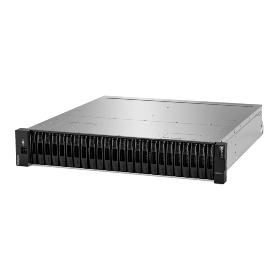
Page 8: Front View
For information about the LEDs on the operator display panel, see “LEDs on the operator display panel” on page 176. For information about the LEDs on drives, see “LEDs on the drives” on page 179. ThinkSystem DE Series Hardware Installation and Maintenance Guide for 2U Enclosures... -
Page 9: Rear View
• : There are two Ethernet ports. The P1 port is the 1Gb Ethernet management port. The P2 port is reserved for Lenovo technical support. • : Depending on the configuration, the optional HIC host ports can be two 10Gb Base-T ports or 12Gb SAS ports. - Page 10 16Gb FC ports, 10/25Gb iSCSI ports, or 32Gb FC ports. For information about the LEDs on the rear view, see “LEDs on the rear of controllers” on page 174 and “LEDs on the power-fan canister” on page 181. ThinkSystem DE Series Hardware Installation and Maintenance Guide for 2U Enclosures...
- Page 11 • : There are two Ethernet ports. The P1 port is the 1Gb Ethernet management port. The P2 port is reserved for Lenovo technical support. • : Depending on the configuration, the optional HIC host ports can be four 12Gb SAS ports, 10/25Gb iSCSI optical ports, or 32Gb FC ports.
-
Page 12: Specifications Of De2000 Series
• 10Gb iSCSI BaseT (RJ-45) System clearance dimension The clearance needed for proper ventilation and heat dissipation is as follows: • Front: 813 mm (32.02 inches) • Rear: 610 mm (24.02 inches) ThinkSystem DE Series Hardware Installation and Maintenance Guide for 2U Enclosures... - Page 13 Specification DE2000H (12 drives) Power input Input power voltage: • Low range: 100–120 V ac • High range: 200–240 V ac Acoustic noise Sound power: 6.6 bels maximum Environment requirements • Air temperature: – Operating: 10°C to 40°C (50°F to 104°F) –...
- Page 14 • Front: 813 mm (32.02 inches) • Rear: 610 mm (24.02 inches) Power input Input power voltage: • Low range: 100–120 V ac • High range: 200–240 V ac ThinkSystem DE Series Hardware Installation and Maintenance Guide for 2U Enclosures...
- Page 15 Specification DE2000H (24 drives) Acoustic noise Sound power: 6.8 bels maximum Environment requirements • Air temperature: – Operating: 10°C to 40°C (50°F to 104°F) – Storage or shipping: –40°C to 70°C (–40°F to 158°F) • Relative humidity: – Operating: 20%–80% –...
-
Page 16: Specifications Of De4000 Series
• Front: 813 mm (32.02 inches) • Rear: 610 mm (24.02 inches) Power input Input power voltage: • Low range: 100–120 V ac • High range: 200–240 V ac ThinkSystem DE Series Hardware Installation and Maintenance Guide for 2U Enclosures... - Page 17 Specification DE4000H (12 drives) Acoustic noise Sound power: 6.6 bels maximum Environment requirements • Air temperature: – Operating: 10°C to 40°C (50°F to 104°F) – Storage or shipping: –40°C to 70°C (–40°F to 158°F) • Relative humidity: – Operating: 20%–80% –...
- Page 18 • Front: 813 mm (32.02 inches) • Rear: 610 mm (24.02 inches) Power input Input power voltage: • Low range: 100–120 V ac • High range: 200–240 V ac ThinkSystem DE Series Hardware Installation and Maintenance Guide for 2U Enclosures...
- Page 19 Specification DE4000H or DE4000F (24 drives) Acoustic noise Sound power: 6.8 bels maximum Environment requirements • Air temperature: – Operating: 10°C to 40°C (50°F to 104°F) – Storage or shipping: –40°C to 70°C (–40°F to 158°F) • Relative humidity: – Operating: 20%–80% –...
-
Page 20: Specifications Of De6000 Series
– For cooling: 813 mm (32.02 inches) – For maintenance: 559 mm (22.02 inches) • Rear: – For cooling: 610 mm (24.02 inches) – For maintenance: 305 mm (12.02 inches) ThinkSystem DE Series Hardware Installation and Maintenance Guide for 2U Enclosures... - Page 21 Specification DE6000H (24 drives) Power input Input power voltage: • Low range: 100–120 V ac • High range: 200–240 V ac Acoustic noise Sound power: 6.7 bels maximum Environment requirements • Air temperature: – Operating: 10°C to 40°C (50°F to 104°F) –...
- Page 22 – For cooling: 610 mm (24.02 inches) – For maintenance: 305 mm (12.02 inches) Power input Input power voltage: • Low range: 100–120 V ac • High range: 200–240 V ac ThinkSystem DE Series Hardware Installation and Maintenance Guide for 2U Enclosures...
- Page 23 Specification DE6000F (24 drives) Acoustic noise Sound power: 6.7 bels maximum Environment requirements • Air temperature: – Operating: 10°C to 40°C (50°F to 104°F) – Storage or shipping: –40°C to 70°C (–40°F to 158°F) • Relative humidity: – Operating: 20%–80% –...
-
Page 24: Specifications Of Drive Shelves
– For cooling: 153 mm (6.02 inches) – For maintenance: 610 mm (24.02 inches) • Rear: – For cooling: 153 mm (6.02 inches) – For maintenance: 330 mm (12.99 inches) ThinkSystem DE Series Hardware Installation and Maintenance Guide for 2U Enclosures... - Page 25 Specification DE120S Power input Input power voltage: • Low range: 100–120 V ac • High range: 200–240 V ac Environment requirements • Air temperature: – Operating: 10°C to 40°C (50°F to 104°F) – Storage or shipping: –40°C to 70°C (–40°F to 158°F) •...
- Page 26 Note: If you plan to operate a system at an altitude between 3280 ft to 9842 ft (1000 m to 3000 m) above sea level, lower the environmental temperature 3.1°F (1.7°C) for every 3280 ft (1000 m) above sea level. ThinkSystem DE Series Hardware Installation and Maintenance Guide for 2U Enclosures...
-
Page 27: Management Software Overview
Management software overview The ThinkSystem SAN OS software is available for DE Series storage management and other tasks. ThinkSystem SAN OS software consists of the following management interfaces: • ThinkSystem System Manager – used to manage one controller in a storage array. •... - Page 28 SecureCLI interface. For detailed information on how to install it, follow instructions in the “Windows express configuration” on page 32, “VMware express configuration” on page 49, or “Linux express configuration” on page 64 for your operating system. ThinkSystem DE Series Hardware Installation and Maintenance Guide for 2U Enclosures...
-
Page 29: Chapter 2. System Setup And Configuration
To get up and running with your system, you install hardware components, configure host systems, and configure storage. Deploying the storage array involves the following workflow: Figure 7. Setup workflow Step 1: Install hardware To install the system hardware, refer to the Installation and Setup Instructions that comes with your system. © Copyright Lenovo 2018... -
Page 30: Cabling Your Storage System
Step 2: Set up a rack Install your system in a 4-post rack or Lenovo system rack, as applicable. If you are setting up a new rack for the storage array, follow instructions that come with the rack. Step 3: Install rails When shipped, each shelf includes rack-mounting hardware. -
Page 31: Host Cabling
• DE120S and DE240S Required components In addition to controller shelves and drive shelves, you might need some or all of the following components when cabling your storage system: • Cables: SAS, Fibre Channel (FC), Ethernet • Small form-factor pluggable (SFP) •... -
Page 32: Drive Shelf Cabling
You must connect each controller in the controller shelf to an Input/Output module (IOM) in a drive shelf. Cabling a 12-drive or 24-drive shelf You can cable your controller shelf to one or more 12-drive or 24-drive shelves with SAS-3 drives. ThinkSystem DE Series Hardware Installation and Maintenance Guide for 2U Enclosures... -
Page 33: Power Cabling
A controller shelf and 12-drive or 24-drive shelves Power cabling You must connect each component's power supplies to separate power circuits. Before you begin • You have confirmed that your location provides the necessary power. • The two power switches on the two shelf power supplies must be turned off. The power source for your storage system must be able to accommodate the power requirements of the new drive shelf. - Page 34 Power on the new drive shelf, and confirm that no amber attention LEDs are illuminated on the drive shelf. If possible, resolve any fault conditions before you continue with this procedure. Go to Connect the drive shelf. ThinkSystem DE Series Hardware Installation and Maintenance Guide for 2U Enclosures...
- Page 35 Connect the drive shelf You connect the drive shelf to controller A, confirm IOM status, and then connect the drive shelf to controller Step 1. Connect the drive shelf to controller A. The following figure shows an example connection between an additional drive shelf and controller A.
- Page 36 Note: You might need to scroll down the page to locate this link. Step 7. If necessary, upgrade the drive firmware. ThinkSystem DE Series Hardware Installation and Maintenance Guide for 2U Enclosures...
-
Page 37: Ethernet Cabling For A Management Station
IOM/ESM firmware automatically upgrades to the latest version unless you have disabled the upgrade feature. The hot add procedure is complete. You can resume normal operations. Ethernet cabling for a management station You can connect your storage system to an Ethernet network for out-of-band storage array management. You must use Ethernet cables for all storage array management connections. -
Page 38: Windows Express Configuration
2. Creating logical volumes on the storage array and assigning a logical unit number (LUN) to each volume. 3. Making the volume LUNs available to the data host. This guide is based on the following assumptions: ThinkSystem DE Series Hardware Installation and Maintenance Guide for 2U Enclosures... - Page 39 Protocol: FC • You have made all host-side FC connections and activated switch zoning. • You are using Lenovo-supported FC HBAs and switches. • You are using FC HBA driver versions as listed on the DE Series Product Support Site Protocol: iSCSI •...
-
Page 40: Understand The Workflow
Host bus adapter (HBA) necessary to update the HBA boot code and driver, firmware, and firmware. bootcode ThinkSystem DE Series Hardware Installation and Maintenance Guide for 2U Enclosures... -
Page 41: Configure Management Port Ip Addresses
Configure management port IP addresses Configure the management port for communication between the management station and array controllers. Before you begin • You have obtained the network configuration information from your network administrator for the controllers (IP address, subnet mask, and gateway or IP address and routable IP address). •... -
Page 42: Install Thinksystem Storage Manager For Smcli And Host Context Agent (Hca)
Use the installation wizard to install the software on the management station. Access ThinkSystem System Manager and use the Setup wizard You use the Setup wizard in ThinkSystem System Manager to configure your storage array. ThinkSystem DE Series Hardware Installation and Maintenance Guide for 2U Enclosures... - Page 43 Before you begin • You have ensured that the device from which you will access ThinkSystem System Manager contains one of the following browsers: Browser Minimum version Google Chrome Microsoft Internet Explorer Microsoft Edge EdgeHTML 12 Mozilla Firefox Safari • You are using out-of-band management. If you are an iSCSI user, make sure you have closed the Setup wizard while configuring iSCSI.
-
Page 44: Perform Fc-Specific Tasks
Appropriate settings for your configuration are listed in the Interoperability Matrix document. Go to DE Series Product Support Site , click on the Documentation tab, and look for the Interoperability Matrix document. ThinkSystem DE Series Hardware Installation and Maintenance Guide for 2U Enclosures... - Page 45 FC worksheet for Windows You can use this worksheet to record FC storage configuration information. You need this information to perform provisioning tasks. The illustration shows a host connected to a DE Series storage array in two zones. One zone is indicated by the blue line;...
-
Page 46: Perform Iscsi-Specific Tasks
You use the ThinkSystem System Manager GUI to configure iSCSI networking on the array side. Before you begin • You must know the IP address or domain name for one of the storage array controllers. ThinkSystem DE Series Hardware Installation and Maintenance Guide for 2U Enclosures... - Page 47 • You or your system administrator must have set up a password for the System Manager GUI, or you must configured Role-Based Access Control (RBAC) or LDAP and a directory service for the appropriate security access to the storage array. See the ThinkSystem System Manager online help for more information about Access Management.
- Page 48 • You have fully configured the switches that will be used to carry iSCSI storage traffic. • You must have enabled send and receive hardware flow control end to end and disabled priority flow control. ThinkSystem DE Series Hardware Installation and Maintenance Guide for 2U Enclosures...
- Page 49 • You have completed the array side iSCSI configuration. • You must know the IP address of each port on the controller. These instructions assume that two NIC ports will be used for iSCSI traffic. Step 1. Disable unused network adapter protocols. These protocols include, but are not limited to, QoS, File and Print Sharing, and NetBIOS.
- Page 50 Note: If the command fails (for example, returns Packet needs to be fragmented but DF set), verify the MTU size (jumbo frame support) for the Ethernet interfaces on the host server, storage controller, and switch ports. ThinkSystem DE Series Hardware Installation and Maintenance Guide for 2U Enclosures...
-
Page 51: Perform Sas-Specific Tasks
Recording iSCSI-specific information for Windows Select the iSCSI worksheet to record your protocol-specific storage configuration information. You need this information to perform provisioning tasks. iSCSI worksheet - Windows You can use this worksheet to record iSCSI storage configuration information. You need this information to perform provisioning tasks. - Page 52 Use the HBA BIOS to select the appropriate settings for your configuration. Go to , click on the Documentation tab, and look for the DE Series Product Support Site Interoperability Matrix document for recommendations. ThinkSystem DE Series Hardware Installation and Maintenance Guide for 2U Enclosures...
-
Page 53: Discover Storage On The Host
Recording SAS-specific information for Windows Record your protocol-specific storage configuration information on the SAS worksheet. You need this information to perform provisioning tasks. SAS worksheet - Windows You can use this worksheet to record SAS storage configuration information. You need this information to perform provisioning tasks. -
Page 54: Configure Storage On The Host
> echo test file > f:\test.txt Step 2. Read the file and verify data was written. > type f:\test.txt Step 3. To verify that multipath is working, change the volume ownership. ThinkSystem DE Series Hardware Installation and Maintenance Guide for 2U Enclosures... -
Page 55: Vmware Express Configuration
From the ThinkSystem System Manager GUI, go to Storage ➙ Volumes, and then select More ➙ Change ownership. On the Change Volume Ownership dialog box, use the Preferred Owner pull-down to select the other controller for one of the volumes in the list, and then confirm the operation. Verify that you can still access the files on the LUN. - Page 56 • You have configured the Ethernet switches according to the vendor’s recommendation for iSCSI. Protocol: SAS • You are using Lenovo-supported SAS HBAs. • You are using SAS HBA driver versions as listed on the DE Series Product Support Site ThinkSystem DE Series Hardware Installation and Maintenance Guide for 2U Enclosures...
- Page 57 Understand the workflow This workflow guides you through the express method for configuring your storage array and ThinkSystem System Manager to make storage available to a host. Verify the configuration is supported. ⇩ Configure management port IP address. ⇩ Configure multipath software, if applicable. ⇩...
- Page 58 Use the installation wizard to install the software on the management station. Access ThinkSystem System Manager and use the Setup wizard You use the Setup wizard in ThinkSystem System Manager to configure your storage array. ThinkSystem DE Series Hardware Installation and Maintenance Guide for 2U Enclosures...
- Page 59 Before you begin • You have ensured that the device from which you will access ThinkSystem System Manager contains one of the following browsers: Browser Minimum version Google Chrome Microsoft Internet Explorer Microsoft Edge EdgeHTML 12 Mozilla Firefox Safari • You are using out-of-band management. If you are an iSCSI user, make sure you have closed the Setup wizard while configuring iSCSI.
- Page 60 Record the initiator identifiers. The output will be similar to this example: vmhba3 lpfc link-up fc.20000090fa05e848:10000090fa05e848 (0000:03:00.0) Emulex Corporation Emulex LPe16000 16Gb PCIe Fibre Channel Adapter vmhba4 lpfc link-up fc.20000090fa05e849:10000090fa05e849 (0000:03:00.1) Emulex Corporation Emulex LPe16000 16Gb PCIe Fibre Channel Adapter ThinkSystem DE Series Hardware Installation and Maintenance Guide for 2U Enclosures...
- Page 61 FC worksheet for VMware You can use this worksheet to record FC storage configuration information. You need this information to perform provisioning tasks. The illustration shows a host connected to a DE Series storage array in two zones. One zone is indicated by the blue line;...
- Page 62 It is meant to be used with arrays that present a single network address for the iSCSI target. Lenovo recommends that iSCSI port binding not be used. For additional information, see the...
- Page 63 If you are using jumbo frames within the IP SAN for performance reasons, make sure to configure the array, switches, and hosts to use jumbo frames. Consult your operating system and switch documentation for information on how to enable jumbo frames on the hosts and on the switches. To enable jumbo frames on the array, complete the steps in Configuring array-side networking—iSCSI.
- Page 64 Select this option, and then enter a static address in the fields. For IPv4, configuration include the network subnet mask and gateway. For IPv6, include the routable IP address and router IP address. ThinkSystem DE Series Hardware Installation and Maintenance Guide for 2U Enclosures...
- Page 65 Port setting Description Enable VLAN support Important: This option is only available in an iSCSI environment. (Available by clicking Show Select this option to enable a VLAN and enter its ID. A VLAN is a logical more settings.) network that behaves like it is physically separate from other physical and virtual local area networks (LANs) supported by the same switches, the same routers, or both.
- Page 66 (jumbo frame support) for the Ethernet interfaces on the host server, storage controller, and switch ports. Step 3. Return to the iSCSI Configuration procedure to finish target discovery. ThinkSystem DE Series Hardware Installation and Maintenance Guide for 2U Enclosures...
- Page 67 Recording iSCSI-specific information for VMware Select the iSCSI worksheet to record your protocol-specific storage configuration information. You need this information to perform provisioning tasks. iSCSI worksheet - VMware You can use this worksheet to record iSCSI storage configuration information. You need this information to perform provisioning tasks.
- Page 68 Use the HBA BIOS to select the appropriate settings for your configuration. Go to , click on the Documentation tab, and look for the DE Series Product Support Site Interoperability Matrix document for recommendations. ThinkSystem DE Series Hardware Installation and Maintenance Guide for 2U Enclosures...
- Page 69 Recording SAS-specific information for VMware Record your protocol-specific storage configuration information on the SAS worksheet. You need this information to perform provisioning tasks. SAS worksheet - VMware You can use this worksheet to record SAS storage configuration information. You need this information to perform provisioning tasks.
- Page 70 • SAS 2. Creating logical volumes on the storage array and assigning a logical unit number (LUN) to each volume. 3. Making the volume LUNs available to the data host. ThinkSystem DE Series Hardware Installation and Maintenance Guide for 2U Enclosures...
-
Page 71: Fibre Channel Express Setup
Protocol: FC • You have made all host-side FC connections and activated switch zoning. • You are using Lenovo-supported FC HBAs and switches. • You are using FC HBA driver versions as listed on the DE Series Product Support Site Protocol: iSCSI •... - Page 72 4. Run the . . / / S S M M I I A A * * . . b b i i n n command to start the installer. ThinkSystem DE Series Hardware Installation and Maintenance Guide for 2U Enclosures...
- Page 73 Step 3. Use the installation wizard to install the software on the management station. Access ThinkSystem System Manager and use the Setup wizard You use the Setup wizard in ThinkSystem System Manager to configure your storage array. Before you begin •...
- Page 74 - - - - f f o o r r c c e e - - - - a a d d d d m m u u l l t t i i p p a a t t h h ThinkSystem DE Series Hardware Installation and Maintenance Guide for 2U Enclosures...
- Page 75 Make sure that the newly created /boot/initrams-* image or /boot/initrd-* image is selected in Step 8. the boot configuration file.For example, for grub it is /boot/grub/menu.lst and for grub2 it is /boot/ grub2/menu.cfg. Step 9. Use the "Create host manually" procedure in the online help to check whether the hosts are defined.
- Page 76 # mount /dev/mapper/360080e5000321bb8000092b1535f887a1 /mnt/ext4 Verify storage access on the host Before using the volume, you verify that the host can write data to the volume and read it back. Before you begin ThinkSystem DE Series Hardware Installation and Maintenance Guide for 2U Enclosures...
- Page 77 You must have initialized the volume and formatted it with a file system. Step 1. On the host, copy one or more files to the mount point of the disk. Step 2. Copy the files back to a different folder on the original disk. Step 3.
- Page 78 Controller A, port 1 to FC switch 1 Controller A, port 2 to FC switch 2 Controller B, port 1 to FC switch 1 Controller B, port 2 to FC switch 2 ThinkSystem DE Series Hardware Installation and Maintenance Guide for 2U Enclosures...
-
Page 79: Sas Express Setup
Mapping host Mapping host name Host OS type SAS Express Setup Verify the Linux configuration is supported To ensure reliable operation, you create an implementation plan and then verify that the entire configuration is supported. Step 1. Go to the DE Series Product Support Site Step 2. - Page 80 After you set a password for the admin role, you can change all of the passwords using the admin credentials. See ThinkSystem System Manager online help for more information on the four local user roles. ThinkSystem DE Series Hardware Installation and Maintenance Guide for 2U Enclosures...
- Page 81 Step 2. Enter the System Manager password for the admin role in the S S e e t t A A d d m m i i n n i i s s t t r r a a t t o o r r P P a a s s s s w w o o r r d d and C C o o n n f f i i r r m m P P a a s s s s w w o o r r d d fields, then select the Set Password button.
- Page 82 In the /dev/mapper folder, you have run the l l s s command to see the available disks. You can initialize the disk as a basic disk with a GUID partition table (GPT) or Master boot record (MBR). ThinkSystem DE Series Hardware Installation and Maintenance Guide for 2U Enclosures...
- Page 83 Format the LUN with a file system such as ext4. Some applications do not require this step. Step 1. Retrieve the SCSI ID of the mapped disk by issuing the s s a a n n l l u u n n l l u u n n s s h h o o w w - - p p command.The SCSI ID is a 33-character string of hexadecimal digits, beginning with the number 3.
- Page 84 1 Host (initiator) port 2 connected to Controller B, port 1 Target Identifiers Recommended configurations consist of two target ports. Mappings Host Mappings Host Name Host OS Type ThinkSystem DE Series Hardware Installation and Maintenance Guide for 2U Enclosures...
-
Page 85: Iscsi Express Setup
iSCSI Express Setup Verify the Linux configuration is supported To ensure reliable operation, you create an implementation plan and then verify that the entire configuration is supported. Step 1. Go to the DE Series Product Support Site Step 2. Click on the Documentation tab. Step 3. - Page 86 After you set a password for the admin role, you can change all of the passwords using the admin credentials. See ThinkSystem System Manager online help for more information on the four local user roles. ThinkSystem DE Series Hardware Installation and Maintenance Guide for 2U Enclosures...
- Page 87 Step 2. Enter the System Manager password for the admin role in the S S e e t t A A d d m m i i n n i i s s t t r r a a t t o o r r P P a a s s s s w w o o r r d d and C C o o n n f f i i r r m m P P a a s s s s w w o o r r d d fields, then select the Set Password button.
- Page 88 VLANs. You must enable send and receive hardware flow control end to end. You must disable priority flow control. ThinkSystem DE Series Hardware Installation and Maintenance Guide for 2U Enclosures...
- Page 89 If you are using jumbo frames within the IP SAN for performance reasons, make sure to configure the array, switches, and hosts to use jumbo frames. Consult your operating system and switch documentation for information on how to enable jumbo frames on the hosts and on the switches. To enable jumbo frames on the array, complete the steps in Configuring array-side networking—iSCSI.
- Page 90 Select this option, and then enter a static address in the fields. For IPv4, configuration include the network subnet mask and gateway. For IPv6, include the routable IP address and router IP address. ThinkSystem DE Series Hardware Installation and Maintenance Guide for 2U Enclosures...
- Page 91 Port setting Description Enable VLAN support Important: This option is only available in an iSCSI environment. (Available by clicking Show Select this option to enable a VLAN and enter its ID. A VLAN is a logical more settings.) network that behaves like it is physically separate from other physical and virtual local area networks (LANs) supported by the same switches, the same routers, or both.
- Page 92 Pinging 192.0.2.8 with 8972 bytes of data: Reply from 192.0.2.8: bytes=8972 time=2ms TTL=64 Reply from 192.0.2.8: bytes=8972 time=2ms TTL=64 Reply from 192.0.2.8: bytes=8972 time=2ms TTL=64 Reply from 192.0.2.8: bytes=8972 time=2ms TTL=64 Ping statistics for 192.0.2.8: ThinkSystem DE Series Hardware Installation and Maintenance Guide for 2U Enclosures...
- Page 93 Packets: Sent = 4, Received = 4, Lost = 0 (0% loss), Approximate round trip times in milli-seconds: Minimum = 2ms, Maximum = 2ms, Average = 2ms Step 2. Issue a p p i i n n g g command from each host’s initiator address (the IP address of the host Ethernet port used for iSCSI) to each controller iSCSI port.
- Page 94 Step 3. Run the d d i i f f f f command to compare the copied files to the originals. Remove the file and folder that you copied. ThinkSystem DE Series Hardware Installation and Maintenance Guide for 2U Enclosures...
- Page 95 Record iSCSI-specific information for Linux Select the iSCSI worksheet to record your protocol-specific storage configuration information. You need this information to perform provisioning tasks. iSCSI worksheet - Linux You can use this worksheet to record iSCSI storage configuration information. You need this information to perform provisioning tasks.
- Page 96 ThinkSystem DE Series Hardware Installation and Maintenance Guide for 2U Enclosures...
-
Page 97: Chapter 3. Hardware Replacement Procedures
• You must have a replacement battery. • You have an ESD wristband, or you have taken other antistatic precautions. • You should use labels to identify each cable that is connected to the controller canister. © Copyright Lenovo 2018... -
Page 98: Replace Battery
Step 4. Collect support data for your storage array using ThinkSystem System Manager. 1. Select Support ➙ Support Center ➙ Diagnostics. 2. Select Collect Support Data. 3. Click Collect. ThinkSystem DE Series Hardware Installation and Maintenance Guide for 2U Enclosures... - Page 99 The file is saved in the Downloads folder for your browser with the name support-data.7z. Step 5. If the controller is not already offline, take it offline now using either ThinkSystem System Manager or the Enterprise Management Window's (EMW) script editor of ThinkSystem Storage Manager. •...
- Page 100 Remove the controller canister's cover by pressing down on the button and sliding the cover off. Step 2. Confirm that the green LED inside the controller (between the battery and the DIMMs) is off. ThinkSystem DE Series Hardware Installation and Maintenance Guide for 2U Enclosures...
- Page 101 If this green LED is on, the controller is still using battery power. You must wait for this LED to go off before removing any components. Internal Cache Active LED Battery Step 3. Locate the blue release latch for the battery. Step 4.
- Page 102 (as shown in the first figure). If the battery is not installed correctly (as shown in the second figure), the metal flange might contact the controller board, causing damage to the controller when you apply power. ThinkSystem DE Series Hardware Installation and Maintenance Guide for 2U Enclosures...
- Page 103 • Correct – The battery's metal flange is completely inserted in the slot on the controller: • Incorrect – The battery's metal flange is not inserted into the slot on the controller: Go to Step 2: Re-install controller canister Step 2: Re-install controller canister Reinstall the controller canister into the controller shelf after installing the new battery.
- Page 104 • The seven-segment display shows the repeating sequence OS, OL, blank to indicate that the controller is offline. • The amber Attention LED remains lit. • The Host Link LEDs might be on, blinking, or off, depending on the host interface. ThinkSystem DE Series Hardware Installation and Maintenance Guide for 2U Enclosures...
- Page 105 Attention LED (amber) Seven-segment display Host Link LEDs Step 2. Bring the controller online using either ThinkSystem System Manager or the Enterprise Management Window's (EMW) script editor of ThinkSystem Storage Manager. • To use ThinkSystem System Manager: 1. Select Hardware. 2.
-
Page 106: Controllers
(CLI). If this software has not yet been installed, follow the instructions in the “Windows express configuration” on page 32, “VMware express configuration” on page 49, or “Linux express configuration” on page 64 to download and install it. ThinkSystem DE Series Hardware Installation and Maintenance Guide for 2U Enclosures... -
Page 107: Replace A Controller
Two-controller configuration If the controller shelf has two controllers, you can replace a controller canister while your storage array is powered on and performing host I/O operations, as long as the following conditions are true: • The second controller canister in the shelf has Optimal status. •... - Page 108 2. If the graphic shows the drives, select Show back of shelf to show the controllers. 3. Select the controller that you want to place offline. 4. From the context menu, select Place offline, and confirm that you want to perform the operation. ThinkSystem DE Series Hardware Installation and Maintenance Guide for 2U Enclosures...
- Page 109 Note: If you are accessing ThinkSystem System Manager using the controller you are attempting to take offline, a System Manager Unavailable message is displayed. Select Connect to an alternate network connection to automatically access ThinkSystem System Manager using the other controller. •...
- Page 110 Remove the controller canister's cover by pressing down on the button and sliding the cover off. Step 2. Confirm that the green LED inside the controller (between the battery and the DIMMs) is off. ThinkSystem DE Series Hardware Installation and Maintenance Guide for 2U Enclosures...
- Page 111 If this green LED is on, the controller is still using battery power. You must wait for this LED to go off before removing any components. Internal Cache Active LED Battery Step 3. Locate the blue release latch for the battery. Step 4.
- Page 112 Carefully detach the HIC from the controller card by lifting the card up and sliding it back. Attention: Be careful not to scratch or bump the components on the bottom of the HIC or on the top of the controller card. ThinkSystem DE Series Hardware Installation and Maintenance Guide for 2U Enclosures...
- Page 113 Host interface card (HIC) Thumbscrews Step 5. Place the HIC on a static-free surface. Go to “Install new controller” on page 107. Install new controller You install a new controller canister to replace the failed one. Perform this task only if your storage array has two controllers.
- Page 114 • Correct – The battery's metal flange is completely inserted in the slot on the controller: • Incorrect – The battery's metal flange is not inserted into the slot on the controller: Go to “Step 2: Install host interface card” on page 109. ThinkSystem DE Series Hardware Installation and Maintenance Guide for 2U Enclosures...
- Page 115 Step 2: Install host interface card If you removed a HIC from the original controller canister, you must install that HIC in the new controller canister. Before you begin • You must have a replacement controller canister with the same part number as the controller canister you are replacing.
- Page 116 With the cam handle in the open position, slide the controller canister all the way into the controller shelf. Controller canister Cam handle Step 4. Move the cam handle to the left to lock the controller canister in place. ThinkSystem DE Series Hardware Installation and Maintenance Guide for 2U Enclosures...
- Page 117 Step 5. Install the SFPs from the original controller in the host ports on the new controller, and reconnect all the cables. If you are using more than one host protocol, be sure to install the SFPs in the correct host ports.
-
Page 118: Power-Fan Canisters
The DE120S and DE240S drive shelves are identical, but they include I/O modules (IOMs) instead of controller canisters. Controller shelf with two power supplies (power-fan canisters) below the controller canisters. ThinkSystem DE Series Hardware Installation and Maintenance Guide for 2U Enclosures... -
Page 119: Replace Power Supply (12-Drive Or
Requirements for replacing a power supply If you plan to replace a power supply, keep the following requirements in mind. • You must have a replacement power supply (power-fan canister) that is supported for your controller shelf or drive shelf model. •... - Page 120 Unpack the new power supply, and set it on a level surface near the drive shelf.Save all packing materials for use when returning the failed power supply. Step 2. Turn off the power supply and disconnect the power cables: ThinkSystem DE Series Hardware Installation and Maintenance Guide for 2U Enclosures...
- Page 121 Turn off the power switch on the power supply. Open the power cord retainer, and then unplug the power cord from the power supply. Unplug the power cord from the power source. Step 3. Squeeze the latch on the power supply cam handle, and then open the cam handle to fully release the power supply from the mid plane.
-
Page 122: Drives
Before you replace a drive, you need to be aware of certain requirements and considerations. Drives overview You can replace a drive in either a 12-drive or 24-drive controller shelf or drive shelf. ThinkSystem DE Series Hardware Installation and Maintenance Guide for 2U Enclosures... - Page 123 12-drive or 24-drive shelves The figures show how the drives are numbered in each type of shelf (the shelf's front bezel or end caps have been removed). Your system might look slightly different from the following figures. Drive numbering in a 12-drive controller shelf or drive shelf Drive numbering in a 24-drive controller shelf or drive shelf Requirements for handling drives The drives in your storage array are fragile.
-
Page 124: Replace Drive (12-Drive Or 24-Drive)
Step 1. Unpack the replacement drive, and set it on a flat, static-free surface near the shelf.Save all packing materials. Step 2. Press the release button on the failed drive. ThinkSystem DE Series Hardware Installation and Maintenance Guide for 2U Enclosures... - Page 125 Otherwise, there is a risk that the equipment might overheat. Before you begin • You have a replacement drive that is supported by Lenovo for your controller shelf or drive shelf. Step 1. Open the cam handle.
-
Page 126: Host Interface Cards
You controller comes with two 16 Gb/s FC or 10 Gb/s iSCSI baseboard host ports. Depending on the controller model, the following types of HICs in each controller model: ThinkSystem DE Series Hardware Installation and Maintenance Guide for 2U Enclosures... - Page 127 Controller model Supported HIC DE2000 Lenovo ThinkSystem DE2000 HIC, 10BaseT, 2-ports Lenovo ThinkSystem DE2000 HIC, 12Gb SAS, 2-ports DE4000 Lenovo ThinkSystem DE4000 HIC, 10/25GbE iSCSI, 4-ports Lenovo ThinkSystem DE4000 HIC, 12Gb SAS, 4-ports Lenovo ThinkSystem DE4000 HIC, 16Gb FC/10GbE iSCSI,4-ports...
- Page 128 • You have installed ThinkSystem Storage Manager on a management station, so you can use the storage array's command line interface (CLI). If this software has not yet been installed, follow the instructions in ThinkSystem DE Series Hardware Installation and Maintenance Guide for 2U Enclosures...
-
Page 129: Add Host Interface Cards
the “Windows express configuration” on page 32, “VMware express configuration” on page 49, or “Linux express configuration” on page 64 to download and install it. Add host interface cards You add host interface cards (HICs) to increase the number of host ports in your storage array and to provide additional host protocols. - Page 130 Label each cable that is attached to the controller canister. Step 2. Disconnect all the cables from the controller canister. Attention: To prevent degraded performance, do not twist, fold, pinch, or step on the cables. ThinkSystem DE Series Hardware Installation and Maintenance Guide for 2U Enclosures...
- Page 131 Step 3. Confirm that the Cache Active LED on the back of the controller is off. The green Cache Active LED on the back of the controller is on when cached data needs to be written to the drives. You must wait for this LED to turn off before removing the controller canister. Cache Active LED Step 4.
- Page 132 Carefully lower the HIC into place, and seat the HIC connector by pressing gently on the HIC. Attention: Possible equipment damage – Be very careful not to pinch the gold ribbon connector for the controller LEDs between the HIC and the thumbscrews. ThinkSystem DE Series Hardware Installation and Maintenance Guide for 2U Enclosures...
- Page 133 Host interface card (HIC) Thumbscrews Step 7. Hand-tighten the HIC thumbscrews.Do not use a screwdriver, or you might over tighten the screws. Step 8. Using a #1 Phillips screwdriver, attach the new HIC faceplate to the controller canister with the four screws you removed previously.
- Page 134 Turn on the two power switches at the back of the controller shelf. • Do not turn off the power switches during the power-on process, which typically takes 90 seconds or less to complete. ThinkSystem DE Series Hardware Installation and Maintenance Guide for 2U Enclosures...
- Page 135 • The fans in each shelf are very loud when they first start up. The loud noise during start-up is normal. Step 2. As the controller boots, check the controller LEDs and seven-segment display. • The seven-segment display shows the repeating sequence OS, Sd, blank to indicate that the controller is performing Start-of-day (SOD) processing.
-
Page 136: Upgrade Host Interface Card
• You have installed ThinkSystem Storage Manager on a management station, so you can use the storage array's command line interface (CLI). Step 1. From the Home of ThinkSystem System Manager, ensure that the storage array has Optimal status. ThinkSystem DE Series Hardware Installation and Maintenance Guide for 2U Enclosures... - Page 137 If the status is not Optimal, use the Recovery Guru or contact technical support to resolve the problem. Do not continue with this procedure. Step 2. Back up the storage array's configuration database. If a problem occurs when you remove a controller, you can use the saved file to restore your configuration.
- Page 138 Depending on what type of HIC you are upgrading to, you might be able to reuse these SFPs. Step 4. Confirm that the Cache Active LED on the back of the controller is off. ThinkSystem DE Series Hardware Installation and Maintenance Guide for 2U Enclosures...
- Page 139 The green Cache Active LED on the back of the controller is on when cached data needs to be written to the drives. You must wait for this LED to turn off before removing the controller canister. Cache Active LED Step 5.
- Page 140 Using a #1 Phillips screwdriver, remove the screws that attach the HIC faceplate to the controller canister.There are four screws: one on the top, one on the side, and two on the front. Step 4. Remove the HIC faceplate. ThinkSystem DE Series Hardware Installation and Maintenance Guide for 2U Enclosures...
- Page 141 Step 5. Using your fingers or a Phillips screwdriver, loosen the three thumbscrews that secure the HIC to the controller card. Step 6. Carefully detach the HIC from the controller card by lifting the card up and sliding it back. Attention: Be careful not to scratch or bump the components on the bottom of the HIC or on the top of the controller card.
- Page 142 LEDs between the HIC and the thumbscrews. Host interface card (HIC) Thumbscrews Step 5. Hand-tighten the HIC thumbscrews.Do not use a screwdriver, or you might over-tighten the screws. ThinkSystem DE Series Hardware Installation and Maintenance Guide for 2U Enclosures...
- Page 143 Step 6. Using a #1 Phillips screwdriver, attach the new HIC faceplate to the controller canister with the four screws you removed previously. Go to Step 4: Reinstall controller canister. Step 4: Reinstall controller canister Reinstall the controller canister into the controller shelf. Step 1.
-
Page 144: Replace Host Interface Card
The process of upgrading a host interface card in your storage array is complete. You can resume normal operations. Replace host interface card You replace a host interface card (HIC) that has failed. If two controllers are present, each controller must have identical HICs. ThinkSystem DE Series Hardware Installation and Maintenance Guide for 2U Enclosures... - Page 145 Prepare to replace host interface card In a two-controller configuration, you must take the affected controller offline before you replace a host interface card (HIC). Place controller offline If you have a two-controller configuration, you must place the affected controller offline so you can safely remove the failed HIC.
- Page 146 • You have an ESD wristband, or you have taken other antistatic precautions. Step 1. Label each cable that is attached to the controller canister. Step 2. Disconnect all the cables from the controller canister. ThinkSystem DE Series Hardware Installation and Maintenance Guide for 2U Enclosures...
- Page 147 Attention: To prevent degraded performance, do not twist, fold, pinch, or step on the cables. Step 3. Confirm that the Cache Active LED on the back of the controller is off. The green Cache Active LED on the back of the controller is on when cached data needs to be written to the drives.
- Page 148 Carefully lower the HIC into place, and seat the HIC connector by pressing gently on the HIC. Attention: Possible equipment damage – Be very careful not to pinch the gold ribbon connector for the controller LEDs between the HIC and the thumbscrews. ThinkSystem DE Series Hardware Installation and Maintenance Guide for 2U Enclosures...
- Page 149 Host interface card (HIC) Thumbscrews Step 7. Hand-tighten the HIC thumbscrews.Do not use a screwdriver, or you might over-tighten the screws. Step 8. Using a #1 Phillips screwdriver, attach the new HIC faceplate to the controller canister with the four screws you removed previously.
- Page 150 When communication with the other controller is reestablished: • The seven-segment display shows the repeating sequence OS, OL, blank to indicate that the controller is offline. ThinkSystem DE Series Hardware Installation and Maintenance Guide for 2U Enclosures...
- Page 151 • The amber Attention LED remains lit. • The Host Link LEDs might be on, blinking, or off, depending on the host interface. Attention LED (amber) Seven-segment display Host Link LEDs Step 2. Bring the controller online using either ThinkSystem System Manager or the Enterprise Management Window's (EMW) script editor of ThinkSystem Storage Manager.
-
Page 152: Host Port Protocol
You can convert the protocol of a host to a different protocol so that compatibility and communication can be established. Overview and requirements Learn about the baseboard host ports and the requirements you need to know about before converting the host protocol. ThinkSystem DE Series Hardware Installation and Maintenance Guide for 2U Enclosures... - Page 153 • If you are attempting to change the baseboard host ports of your storage array, and it currently uses dual- protocol (also referred to as unified) SFP transceivers that you purchased from Lenovo, you do not need to change your SFP transceivers.
- Page 154 In addition, follow the instructions in the online help to deactivate Asynchronous Mirroring. Converting from FC to FC/iSCSI Mirroring considerations ThinkSystem DE Series Hardware Installation and Maintenance Guide for 2U Enclosures...
- Page 155 • If a storage array used for mirroring currently has only FC ports, and you want to convert some of them to iSCSI, you must determine which ports are used for mirroring. • You do not need to convert the ports on the local storage array and the remote storage array to the same protocol as long as both storage arrays have at least one active FC port after the conversion.
- Page 156 HIC ports mirroring ports HIC ports mirroring Required steps Synchronize mirror consistency iSCSI groups before and test communications after Delete mirroring relationships before and re- iSCSI establish mirroring after ThinkSystem DE Series Hardware Installation and Maintenance Guide for 2U Enclosures...
-
Page 157: Change Host Protocol
Converting from FC/iSCSI to iSCSI • Synchronous Mirroring is not supported for iSCSI. • If you plan to convert the ports that are being used for mirrored relationships, you must deactivate mirroring relationships before applying the feature pack. Attention: Possible data loss – If you do not delete the mirroring relationships that occurred over FC before converting the ports to iSCSI, the controllers might lock down, and you might lose data. - Page 158 From ThinkSystem System Manager, select Support ➙ Support Center. With the Support Resources tab selected, scroll to the View top storage array properties section. Locate the Chassis Serial Number, and copy this value to a text file. ThinkSystem DE Series Hardware Installation and Maintenance Guide for 2U Enclosures...
- Page 159 Step 2. Locate the feature pack submodel ID. From the ThinkSystem System Manager, select Support. Select the Support Center tile. On the Support Resources tab, locate and select the Storage Array Profile link. Type feature pack submodel ID in the text box, and click Find. Locate the feature pack submodel ID for the starting configuration.
- Page 160 B4XG iSCSI iSCSI iSCSI B4XQ iSCSI iSCSI iSCSI B4XS DE4000F B4DK iSCSI iSCSI B4XU iSCSI iSCSI B4G7 B4DL iSCSI B4XW iSCSI iSCSI iSCSI iSCSI iSCSI B4XY iSCSI B4XV ThinkSystem DE Series Hardware Installation and Maintenance Guide for 2U Enclosures...
- Page 161 Starting configuration Ending configuration Con- Base- ports (if Base- ports (if troller board board submo- Controller ports SAS) ports SAS) del ID submodel ID Feature Code iSCSI iSCSI B4XX iSCSI iSCSI iSCSI B4Y0 iSCSI iSCSI B4XT iSCSI iSCSI iSCSI B4XZ iSCSI iSCSI iSCSI...
- Page 162 From the Home page of ThinkSystem System Manager, select View Operations in Progress. Step 5. Wait for all operations to complete before continuing with the next step. Go to Change the feature pack ThinkSystem DE Series Hardware Installation and Maintenance Guide for 2U Enclosures...
- Page 163 Change the feature pack You change the feature pack to convert the host protocol of the baseboard host ports and the host ports on the DE4000 16G FC or 10GbE iSCSI HIC. Step 1. From ThinkSystem System Manager, select Settings ➙ System. Step 2.
- Page 164 Step 6. Remount volumes or start using block volume. Complete iSCSI to FC conversion If you converted all host ports from iSCSI to FC, you must configure FC networking. ThinkSystem DE Series Hardware Installation and Maintenance Guide for 2U Enclosures...
- Page 165 Step 1. Install the HBA utility and determine initiator WWPNs. Step 2. Zone the switches. Zoning the switches enables the hosts to connect to the storage and limits the number of paths. You zone the switches using the management interface of the switches. Step 3.
- Page 166 Provide an FC topology for the converted ports. For example, convert any switches from iSCSI to Step 3. If you are not already using dual-protocol SFPs, remove the iSCSI SFPs from the converted ports, and replace them with FC SFPs or dual-protocol SFPs. ThinkSystem DE Series Hardware Installation and Maintenance Guide for 2U Enclosures...
- Page 167 Step 4. Attach cables to the SFPs in the converted ports, and confirm they are connected to the correct FC switch or host. Step 5. Power on the hosts. Step 6. Configure the FC hosts. Step 7. Edit the host partition to add the FC host port IDs and remove the iSCSI host port IDs. Step 8.
- Page 168 • You might need to use specific tools and options that are provided with your operating system to make the volumes available (that is, assign drive letters, create mount points, and so on). Refer to your host operating system documentation for details. ThinkSystem DE Series Hardware Installation and Maintenance Guide for 2U Enclosures...
-
Page 169: Chapter 4. System Upgrade
Configuration for your operating system. You can view your current software and firmware versions in the Software and Firmware Inventory dialog box. Go to Support ➙ Upgrade Center, and then click the link for Software and Firmware Inventory. © Copyright Lenovo 2018... - Page 170 System Manager automatically checks compatibility during the upgrade process. Drive upgrade methods There are two types of drive firmware upgrade methods: online and offline. ThinkSystem DE Series Hardware Installation and Maintenance Guide for 2U Enclosures...
- Page 171 Online upgrade Offline upgrade During an online upgrade, drives are upgraded During an offline upgrade, all drives of the same sequentially, one at a time. The storage array drive type are upgraded at the same time. This continues processing I/O while the upgrade occurs. method requires stopping I/O activity to the You do not have to stop I/O.
-
Page 172: Upgrade Controller Software And Firmware
(NVSRAM) to make sure you have all the latest features and bug fixes. Download software files from support site You download the new downloadable package (DLP) software files from the Lenovo Support Web site to your management client. - Page 173 Select the ThinkSystem SAN OS Software file by clicking Browse and navigating to the OS software file you downloaded from the Support web site. Select the Controller NVSRAM file by clicking Browse and navigating to the NVSRAM file that you downloaded from the Support site. Controller NVSRAM files have a filename similar to N2800-830000-000.dlp.
- Page 174 Manager to monitor the progress of the operations. Missing volumes You must correct the missing volume condition before the firmware can be upgraded. Launch System Manager and use the Recovery Guru to resolve the problem. ThinkSystem DE Series Hardware Installation and Maintenance Guide for 2U Enclosures...
-
Page 175: Upgrade Drive Firmware
You upgrade your drives' firmware to make sure you have all the latest features and bug fixes. Download drive firmware files from support site You download the drive firmware files from the Lenovo Support Web site to your management client. Step 1. - Page 176 Click Start, and confirm that you want to perform the operation. If you need to stop the upgrade, click Stop. Any firmware downloads currently in progress complete. Any firmware downloads that have not started are canceled. ThinkSystem DE Series Hardware Installation and Maintenance Guide for 2U Enclosures...
- Page 177 Attention: Stopping the drive firmware upgrade might result in data loss or unavailable drives. Step 8. (Optional) To see a list of what was upgraded, click Save Log. The file is saved in the Downloads folder for your browser with the name latest-upgrade-log- timestamp.txt.
- Page 178 More than 4 critical MEL entries in the last 7 Contact technical support to resolve this issue. days Your drive firmware upgrade is complete. You can resume normal operations. ThinkSystem DE Series Hardware Installation and Maintenance Guide for 2U Enclosures...
-
Page 179: Chapter 5. System Monitoring
You can find LEDs on the following components: • DE2000/DE4000/DE6000 controllers (2U) • Operator display panel • I/O modules (IOMs) • Drives • Power-fan canisters In addition to LEDs, each controller has a seven-segment display, which indicates the operational status of the controller. © Copyright Lenovo 2018... -
Page 180: Leds On The Rear Of Controllers
SAS Expansion Port Link Status SAS Expansion Port Attention Baseboard Host Port Link Status Baseboard Host Port Attention Ethernet Status Ethernet Activity The following table describes the controller LEDs and their operational statuses: ThinkSystem DE Series Hardware Installation and Maintenance Guide for 2U Enclosures... - Page 181 Status Description indicator Cache Active Green The cache contains data not yet written to disk. Either the cache is inactive or all data from the cache has been preserved in non-volatile memory. Locate Blue There is an active request to physically locate the controller shelf.
-
Page 182: Leds On The Operator Display Panel
Note: The location LED turns off automatically after 30 minutes. The location LED is not activated. Shelf ID digital display Number displayed Display the digital shelf ID. ThinkSystem DE Series Hardware Installation and Maintenance Guide for 2U Enclosures... - Page 183 Setting the shelf ID with the ODP push button You can set or change the shelf ID for a controller shelf or a drive shelf by using the ODP push button. Before you begin Each controller shelf or drive shelf has LEDs located on the operator display panel (ODP). You might need to remove the left end cap to see the ODP push button.
- Page 184 Lock in the desired number, and exit the programming mode by pressing and holding the button until the second number stops blinking.It might take up to three seconds for the second number to stop blinking. ThinkSystem DE Series Hardware Installation and Maintenance Guide for 2U Enclosures...
-
Page 185: Leds On The Drives
LEDs on the drives The drives that are installed in a controller shelf or drive shelf include an Activity LED and an Attention LED. The following figure shows the LEDs on the 2.5-inch drives. Figure 18. LEDs on the 2.5-inch drives The following figure shows the LEDs on the 3.5-inch drives. -
Page 186: Leds On The Ioms
Locate LED on the left end cap of the drive shelf is also activated. Locate LEDs turn off automatically after 30 minutes. There is no active request to locate the drive shelf. ThinkSystem DE Series Hardware Installation and Maintenance Guide for 2U Enclosures... -
Page 187: Leds On The Power-Fan Canister
LEDs on the power-fan canister The power-fan canister has LEDs and its own power switch and power outlet. Each 12-drive or 24-drive shelf has two of these canisters. The following illustration shows the LEDs on the power-fan canister. Figure 21. LEDs on the power-fan canister Description Status Power LED... -
Page 188: Seven-Segment Display Overview
SE, followed by Sx, in which SE is the category code and Sx is the detail code. When the seven-segment display sequence starts, the Diagnostic LED is on (green). The following table includes the seven-segment display sequence codes and descriptions: ThinkSystem DE Series Hardware Installation and Maintenance Guide for 2U Enclosures... - Page 189 Category Category code Detail code Startup error • 88: Power-on default • dF: Power-on diagnostic fault • Sx: Power-on validation error Operational error • Lx: Lock-down codes See “Seven-segment display lock- down codes” on page 185. Operational state • OL: Offline •...
- Page 190 The controller is suspended and there are no other errors to report OH Lx blank- All lock-down conditions The controller is suspended because of component errors OE L2 -- CF Px blank- Persistent processor DIMM error correcting code (ECC) errors ThinkSystem DE Series Hardware Installation and Maintenance Guide for 2U Enclosures...
- Page 191 Display sequence Use case OE L2 -- CF Cx blank- Persistent cache DIMM ECC errors OE L2 -- CF dx blank- Persistent processor or cache DIMM ECC errors The controller is suspended as a result of persistent cache backup configuration errors OE LC blank- The write-protect switch is set during cache restore OE L2 -- CF dx blank-...
-
Page 192: Critical Events Reference
Defaults to "Not Available" if component type cannot be identified. Event component location This data is not populated by the embedded SNMP agent running on the controller at this time. ThinkSystem DE Series Hardware Installation and Maintenance Guide for 2U Enclosures... - Page 193 MIB variable field Description Event severity String representation of the severity of the MEL event that prompted the trap. Defaults to "Unknown" if severity cannot be identified. Event priority String representation of the priority of the MEL event that prompted the trap. Defaults to "Unknown" if priority cannot be identified.
- Page 194 Event Specific Data - Optional data is not provided with this event. RecoveryFailureType - N/A MEL_EV_FC_SPEED_NEG_FAILURE - 0x1208 This event occurs when: A data rate negotiation fails. Event Name - FC Speed Neg Failure ThinkSystem DE Series Hardware Installation and Maintenance Guide for 2U Enclosures...
- Page 195 Event description: Data rate negotiation failed Event Group - Fibre Channel Source Driver Event Priority - CRITICAL_EVENT Log Group - Controller (0x1) Event Category - Error (0x1) Event Component Type - Channel (0x0, 0x6) Event Specific Data - Optional data is not provided with this event. RecoveryFailureType - N/A MEL_EV_DEGRADE_CHANNEL - 0x1209 This event occurs when: A drive channel is set to degraded.
- Page 196 This event occurs when: A loop or minihub diagnostics detect that the controller is the bad device on the loop. Event Name - Loop Diagnostic Failure Event description: Controller loop-back diagnostics failed ThinkSystem DE Series Hardware Installation and Maintenance Guide for 2U Enclosures...
- Page 197 Event Group - Fibre Channel-specific Destination Driver Event Priority - CRITICAL_EVENT Log Group - System (0x0) Event Category - Notification (0x4) Event Component Type - Controller (0x0, 0x8) Event Specific Data - Optional data is not provided with this event. RecoveryFailureType - N/A MEL_EV_DFC_CHANNEL_MISWIRE - 0x150F This event occurs when: Two channels are connected with one or more ESMs in between.
- Page 198 SFP, resulting in a port bypass. Could also be Are is a faulty SFP, cable, or ESM. Event Name - Link Speed Detection Failure Event description: Optical link speed detection failure ThinkSystem DE Series Hardware Installation and Maintenance Guide for 2U Enclosures...
- Page 199 Event Group - Fibre Channel-specific Destination Driver Event Priority - CRITICAL_EVENT Log Group - System (0x0) Event Category - Error (0x1) Event Component Type - Channel (0x0, 0x6) Event Specific Data - Optional data is not provided with this event. RecoveryFailureType - REC_LINK_SPEED_DETECTION_MISMATCH ( dataRateMismatch.html ) MEL_EV_DFC_CTL_MISWIRE - 0x151E This event occurs when: This error is logged only for controllers with integrated drive channel ports.
- Page 200 Event Specific Data - Optional data is not provided with this event. RecoveryFailureType - REC_FIBRE_TRUNK_MISWIRE ( fcTrunkingMiswire.html ) MEL_EV_SAS_FRNT_END_MISWIRE - 0x1650 This event occurs when: Two ESMs or controllers, residing in the same tray, are cabled together. ThinkSystem DE Series Hardware Installation and Maintenance Guide for 2U Enclosures...
- Page 201 Event Name - SAS Front End Miswire Event description: SAS host channel miswire detected Event Group - SAS-Specific Source Driver and Miscellaneous Event Priority - CRITICAL_EVENT Log Group - System (0x0) Event Category - Error (0x1) Event Component Type - Channel (0x0, 0x6) Event Specific Data - Optional data is not provided with this event.
- Page 202 Event Component Type - Tray Component (ESM, GBIC/SFP, Power Supply, or Fan) (0x0, 0x7) Event Specific Data - Optional data is not provided with this event. RecoveryFailureType - REC_SAS_PORT_MISWIRED ( SASMiswire.html ), REC_SAS_LOOP_MISWIRE ( SASLoopMiswire.html ) ThinkSystem DE Series Hardware Installation and Maintenance Guide for 2U Enclosures...
- Page 203 MEL_EV_DSAS_BK_END_HBA_MISWIRE - 0x1702 This event occurs when: A RAID controller detects a SAS adapter miswire. Event Name - DSAS Back End HBA Miswire Event description: SAS host adapter miswire detected Event Group - SAS-Specific Destination Driver Event Priority - CRITICAL_EVENT Log Group - System (0x0) Event Category - Error (0x1) Event Component Type - Tray Component (ESM, GBIC/SFP, Power Supply, or Fan) (0x0, 0x7)
- Page 204 Event Category - Error (0x1) Event Component Type - Tray Component (ESM, GBIC/SFP, Power Supply, or Fan) (0x0, 0x7) Event Specific Data - Optional data is not provided with this event. ThinkSystem DE Series Hardware Installation and Maintenance Guide for 2U Enclosures...
- Page 205 RecoveryFailureType - REC_SAS_PORT_MISWIRED ( SASMiswire.html ) MEL_EV_DSAS_WPORT_OPT_TO_DEG_CTLR - 0x170F This event occurs when: At least one of the phys that comprise a port is determined to be connected to an attached device, but the remaining port phys cannot connect to or communicate with an attached device. Event Name - Controller Wide Port Has Gone To Degraded State Event description: Controller wide port has gone to degraded state Event Group - SAS-Specific Destination Driver...
- Page 206 Event Name - Failed Host Interface Card Event description: Failed host interface card Event Group - Controller Field Replaceable HW Event Priority - CRITICAL_EVENT Log Group - Controller (0x1) Event Category - Failure (0x2) ThinkSystem DE Series Hardware Installation and Maintenance Guide for 2U Enclosures...
- Page 207 Event Component Type - Host I/O Card (0x2, 0xD) Event Specific Data - Optional data is provided with this event. MEL_SYMBOL_DATA_SLOTNUMBER RecoveryFailureType - REC_HOST_BOARD_FAULT ( hostCardFault.html ) MEL_EV_MISSING_DRIVE_LOCKDOWN - 0x1907 This event occurs when: A controller is locked down due to detecting enough missing drives that if left alone would result in failed volumes.
- Page 208 Event Name - Drive Failure From Un-Recoverable Read Error Event description: Drive failed due to un-recoverable read error during scan Event Group - VDD Event Priority - CRITICAL_EVENT Log Group - Controller (0x1) ThinkSystem DE Series Hardware Installation and Maintenance Guide for 2U Enclosures...
- Page 209 Event Category - Failure (0x2) Event Component Type - Controller (0x0, 0x8) Event Specific Data - Optional data is not provided with this event. RecoveryFailureType - REC_FAILED_DRIVE ( failedDrive.html ) MEL_EV_REDUN_GROUP_NOT_CONSISTENT - 0x2045 This event occurs when: As part of a reconfiguration operation, a redundancy group is determined to be inconsistent.
- Page 210 MEL_EV_PI_SERVICE_MODE_ENTERED - 0x2069 This event occurs when: This event is logged when the controller has been rebooted into Service Mode because the controller has detected excessive Data Assurance errors. ThinkSystem DE Series Hardware Installation and Maintenance Guide for 2U Enclosures...
- Page 211 Event Name - Data Assurance Service Mode Entered Event description: Controller is in Service Mode due to excessive Data Assurance errors Event Group - Protection Information Event Priority - CRITICAL_EVENT Log Group - Controller (0x1) Event Category - Notification (0x4) Event Component Type - Controller (0x0, 0x8) Event Specific Data - Optional data is not provided with this event.
- Page 212 Event Category - Error (0x1) Event Component Type - Controller (0x0, 0x8) Event Specific Data - Optional data is provided with this event. MEL_DATA_LBA_INFO RecoveryFailureType - REC_CACHE_DATA_LOSS ( cache_failed_data_loss.html ) ThinkSystem DE Series Hardware Installation and Maintenance Guide for 2U Enclosures...
- Page 213 MEL_EV_CACHE_MEM_DIAG_FAIL - 0x2110 This event occurs when: A persistent RPA Memory Parity error is detected. A test of the cache memory (the data buffer on the controller) fails. The test is initiated with the startCacheMemoryDiagnostic_1 SYMbolAPI command. When the error occurs, the controller logs this event and locks down. Event Name - Cache Memory Diagnostic Fail Event description: Controller cache memory initialization failed Event Group - Cache Manager...
- Page 214 Log Group - System (0x0) Event Category - Error (0x1) Event Component Type - Controller (0x0, 0x8) Event Specific Data - Optional data is not provided with this event. ThinkSystem DE Series Hardware Installation and Maintenance Guide for 2U Enclosures...
- Page 215 RecoveryFailureType - REC_CACHE_BACKUP_DEVICE_INSUFFICIENT_CAPACITY ( cacheBackupDevInsuffCapacity.html ) MEL_EV_INSUFFICIENT_MEMORY_FOR_CACHE_SIZE - 0x2120 This event occurs when: The controller has insufficient processor memory to support the configured cache. Event Name - Insufficient Processor Memory For Cache Event description: Insufficient processor memory for cache Event Group - Cache Manager Event Priority - CRITICAL_EVENT Log Group - System (0x0) Event Category - Error (0x1)
- Page 216 Event description: Write-back caching forcibly disabled Event Group - Cache Manager Event Priority - CRITICAL_EVENT Log Group - System (0x0) Event Category - Notification (0x4) Event Component Type - Controller (0x0, 0x8) ThinkSystem DE Series Hardware Installation and Maintenance Guide for 2U Enclosures...
- Page 217 Event Specific Data - Optional data is provided with this event. MEL_DATA_VOLUMES_INFO RecoveryFailureType - REC_WB_CACHING_FORCIBLY_DISABLED ( wBcacheDisabled.html ) MEL_EV_RCB_CACHE_DATA_LOSS - 0x212E This event occurs when: Recovery control block information has been lost either while restoring from a backup device or some other reason. Event Name - Recovery Control Block Cache Data Loss Event description: Cached data may have been lost Event Group - Cache Manager...
- Page 218 Event Name - Wrong Sector Size Event description: Drive has wrong block size Event Group - Configuration Manager Event Priority - CRITICAL_EVENT Log Group - System (0x0) Event Category - Notification (0x4) ThinkSystem DE Series Hardware Installation and Maintenance Guide for 2U Enclosures...
- Page 219 Event Component Type - Drive (0x0, 0x1) Event Specific Data - Optional data is provided with this event. MEL_DATA_WRONG_SECTOR_SIZE RecoveryFailureType - REC_DRIVE_INCOMPATIBLE_SECTOR_SIZE ( sectorSizeIncompatible.html ) MEL_EV_DRV_FORMAT_FAILED - 0x224B This event occurs when: A configuration manager posts an UA/AEN of ASC/ASCQ = 0x3F/0x86 indicating the controller set the drive state to Failed Format failure.
- Page 220 SOD. Event Name - CFG Read Failure Event description: Drive failed - reconstruction failure Event Group - Configuration Manager Event Priority - CRITICAL_EVENT Log Group - System (0x0) ThinkSystem DE Series Hardware Installation and Maintenance Guide for 2U Enclosures...
- Page 221 Event Category - State (0x5) Event Component Type - Drive (0x0, 0x1) Event Specific Data - Optional data is not provided with this event. RecoveryFailureType - N/A MEL_EV_FAIL_VDSK_DELAYED - 0x2252 This event occurs when: A specified device is failed during interrupted write processing. SK/ASC/ASCQ = 0x06/0x3F/0x98 will be offloaded for each failing device.
- Page 222 This event occurs when: A drive transitions to incompatible due to a invalid volume group configuration. Event Name - Incompatible Drive Due To Invalid Configuration Event description: Incompatible drive due to invalid configuration on drive Event Group - Configuration Manager ThinkSystem DE Series Hardware Installation and Maintenance Guide for 2U Enclosures...
- Page 223 Event Priority - CRITICAL_EVENT Log Group - Drive (0x2) Event Category - Notification (0x4) Event Component Type - Drive (0x0, 0x1) Event Specific Data - Optional data is not provided with this event. RecoveryFailureType - REC_ADOPTION_FAILED_RAID_LEVEL_UNSUPPORTED ( sodAdoptFailUnsupportedRAID.html ), REC_DB_ADOPTION_HARD_LIMIT_EXCEEDED ( sodAdoptFailHardLimitExceeded.html ), REC_DRIVE_INCOMPATIBLE_DOWNREV_DACSTORE ( downrevDacstoreIncomplete.html ), REC_DRIVE_INCOMPATIBLE_SECTOR_SIZE ( sectorSizeIncompatible.
- Page 224 Event description: Solid state disk drive at end of life Event Group - Configuration Manager Event Priority - CRITICAL_EVENT Log Group - Drive (0x2) Event Category - Notification (0x4) Event Component Type - Drive (0x0, 0x1) ThinkSystem DE Series Hardware Installation and Maintenance Guide for 2U Enclosures...
- Page 225 Event Specific Data - Optional data is not provided with this event. RecoveryFailureType - REC_SSD_AT_END_OF_LIFE ( ssdEndOfLife.html ) MEL_EV_DRIVE_UNSUPPORTED_CAPACITY - 0x2271 This event occurs when: The controller firmware detects a drive that has a capacity which is unsupported. Event Name - Physical Drive Has Unsupported Capacity Event description: Physical drive has unsupported capacity Event Group - Configuration Manager Event Priority - CRITICAL_EVENT...
- Page 226 Event description: Interposer FW version unsupported Event Group - Configuration Manager Event Priority - CRITICAL_EVENT Log Group - Drive (0x2) Event Category - Notification (0x4) Event Component Type - Drive (0x0, 0x1) ThinkSystem DE Series Hardware Installation and Maintenance Guide for 2U Enclosures...
- Page 227 Event Specific Data - Optional data is not provided with this event. RecoveryFailureType - REC_DRIVE_UNSUPPORTED_INTERPOSER_FW_VERSION ( driveUnsupportedInterposerFWVersion.html ) MEL_EV_INCOMPATIBLE_ALIGNMENT_FOR_EMULATION_DRIVE - 0x2278 This event occurs when: Locking out an emulation drive that has a non-zero lowest aligned LBA. An emulation drive is one in which the logical and physical block sizes are not identical and therefore emulates the logical block size.
- Page 228 Event Name - Primary/Secondary NTP Server Unreachable Event description: Either the NTP server's resolved or configured IP address is wrong or the IP address is unavailable via the attached network ThinkSystem DE Series Hardware Installation and Maintenance Guide for 2U Enclosures...
- Page 229 Event Group - Configuration Manager Event Priority - CRITICAL_EVENT Log Group - System (0x0) Event Category - Notification (0x4) Event Component Type - Controller (0x0, 0x8) Event Specific Data - Optional data is not provided with this event. RecoveryFailureType - REC_NET_NTP_QUERY_FAIL ( ntpQueryFailed.html ) MEL_EV_CFG_NTP_SERVICE_UNAVAIL - 0x2289 This event occurs when: All SNTP queries to the configured Primary and Secondary NTP Servers have failed.
- Page 230 RecoveryFailureType - REC_FAILED_I2C_BUS ( failed_i2c_bus.html ) MEL_EV_SBB_VPD_EEPROM_CORRUPTION - 0x2305 This event occurs when: VPD data in the Storage Bridge Bay EEPROM is corrupted. Event Name - VPD EEPROM Corruption Event description: VPD EEPROM corruption ThinkSystem DE Series Hardware Installation and Maintenance Guide for 2U Enclosures...
- Page 231 Event Group - SBB Validation Event Priority - CRITICAL_EVENT Log Group - System (0x0) Event Category - Error (0x1) Event Component Type - Enclosure (0x0, 0xA) Event Specific Data - Optional data is provided with this event. MEL_DATA_TRAY_ID RecoveryFailureType - REC_CORRUPT_VPD_EEPROM ( corrupt_vpd_eeprom.html ) MEL_EV_CONTROLLER - 0x2500 This event occurs when: A controller is removed from an array configured to use dual controllers.
- Page 232 This event occurs when: Multiple mismatched drive lock key ids are detected by the firmware. Event Name - Multiple Mismatched Key Ids Found Event description: Multiple mismatched key ids found Event Group - Start of Day ThinkSystem DE Series Hardware Installation and Maintenance Guide for 2U Enclosures...
- Page 233 Event Priority - CRITICAL_EVENT Log Group - System (0x0) Event Category - Failure (0x2) Event Component Type - Controller (0x0, 0x8) Event Specific Data - Optional data is not provided with this event. RecoveryFailureType - REC_MULTIPLE_MISMATCHED_KEY_IDS_FOUND ( multiMismatchKeyIDs.html ) MEL_EV_ON_BATTERY - 0x2801 This event occurs when: A UPS battery starts to supply power to the subsystem.
- Page 234 NOINPUT ( supportCRUNoInput.html ) MEL_EV_ENCL_FAIL - 0x280D This event occurs when: An enclosure has transitioned to the Failed state. Event Name - Enclosure Fail Event description: Drive tray component failed or removed ThinkSystem DE Series Hardware Installation and Maintenance Guide for 2U Enclosures...
- Page 235 Event Group - Sub System Monitor Event Priority - CRITICAL_EVENT Log Group - System (0x0) Event Category - Notification (0x4) Event Component Type - Enclosure (0x0, 0xA) Event Specific Data - Optional data is provided with this event. MEL_SYMBOL_DATA_SLOTNUMBER RecoveryFailureType - REC_FAN_UNKNOWN_STAT ( unknownCompStatus.html ), REC_REMOVED_ESM ( removedEsm.html ), REC_SUPPORT_CRU_NOINPUT ( supportCRUNoInput.html ) MEL_EV_ENCL_ID_CONFLICT - 0x2816 This event occurs when: A controller detects duplicate drive tray IDs in the subsystem.
- Page 236 RecoveryFailureType - REC_REMOVED_TEMP_SENSOR ( removedSupportCRU.html ) MEL_EV_ESM_VERSION_MISMATCH - 0x281E This event occurs when: A controller detects that two IOMs (ESMs) do not have the same version of firmware running. ThinkSystem DE Series Hardware Installation and Maintenance Guide for 2U Enclosures...
- Page 237 Event Name - ESM Version Mismatch Event description: IOM (ESM) firmware mismatch Event Group - Sub System Monitor Event Priority - CRITICAL_EVENT Log Group - System (0x0) Event Category - Notification (0x4) Event Component Type - Tray Component (ESM, GBIC/SFP, Power Supply, or Fan) (0x0, 0x7) Event Specific Data - Optional data is provided with this event.
- Page 238 Event Component Type - Drive (0x0, 0x1) Event Specific Data - Optional data is provided with this event. MEL_SYMBOL_DATA_TRAYNUMBER RecoveryFailureType - REC_DRIVE_BYPASSED_SINGLE_PORT ( bypassedDrive.html ), REC_LOST_ REDUNDANCY_DRIVE ( noRedundancyDrive.html ) ThinkSystem DE Series Hardware Installation and Maintenance Guide for 2U Enclosures...
- Page 239 MEL_EV_UNSUPPORTED_LHA_SATA_ESM - 0x282F This event occurs when: A firmware download to an IOM (ESM) fails because the IOM (ESM) firmware is not compatible with the version of controller firmware on the storage array. Event Name - Unsupported LHA SATA ESM Detected Event description: Incompatible version of IOM (ESM) firmware detected Event Group - Sub System Monitor Event Priority - CRITICAL_EVENT...
- Page 240 Event description: Controller host interface card ID mismatch Event Group - Sub System Monitor Event Priority - CRITICAL_EVENT Log Group - System (0x0) Event Category - Notification (0x4) Event Component Type - Controller (0x0, 0x8) ThinkSystem DE Series Hardware Installation and Maintenance Guide for 2U Enclosures...
- Page 241 Event Specific Data - Optional data is not provided with this event. RecoveryFailureType - REC_CTL_MISMATCH ( ctrlMismatch.html ) MEL_EV_DRIVE_TRAYS_NOT_GROUPED_TOGETHER - 0x2835 This event occurs when: A storage array configuration requires drive trays to be sequentially cabled together, but they are not. Event Name - Drive Trays Not Grouped Together Event description: Drive trays not cabled correctly Event Group - Sub System Monitor...
- Page 242 Event Name - Controller Submodel Mismatch Event description: Controller submodel mismatch Event Group - Sub System Monitor Event Priority - CRITICAL_EVENT Log Group - System (0x0) Event Category - Notification (0x4) ThinkSystem DE Series Hardware Installation and Maintenance Guide for 2U Enclosures...
- Page 243 Event Component Type - Controller (0x0, 0x8) Event Specific Data - Optional data is not provided with this event. RecoveryFailureType - REC_SUBMODEL_MISMATCH ( ctrlMismatch.html ) MEL_EV_ESM_TYPE_MISMATCH - 0x2849 This event occurs when: A controller detects an IOM (ESM) hardware mismatch in an enclosure in the storage array.
- Page 244 Event Name - Factory Def Mismatch Event description: IOM (ESM) configuration settings version mismatch Event Group - Sub System Monitor Event Priority - CRITICAL_EVENT Log Group - System (0x0) ThinkSystem DE Series Hardware Installation and Maintenance Guide for 2U Enclosures...
- Page 245 Event Category - Error (0x1) Event Component Type - Enclosure (0x0, 0xA) Event Specific Data - Optional data is provided with this event. MEL_DATA_EDL_MEL_SWAPPED_B RecoveryFailureType - REC_ESM_FACTORY_DEFAULTS_MISMATCH ( esmConfigSettingsMismatch.html ) MEL_EV_ESM_DRIVE_BYPASS - 0x2854 This event occurs when: A Fibre Channel drive port is bypassed by an ESM because the error thresholds have been exceeded.
- Page 246 This event occurs when: An expansion tray is shutdown for thermal reasons. Event Name - Expansion Tray Thermal Shutdown Event description: Expansion tray thermal shutdown Event Group - Sub System Monitor Event Priority - CRITICAL_EVENT ThinkSystem DE Series Hardware Installation and Maintenance Guide for 2U Enclosures...
- Page 247 Log Group - System (0x0) Event Category - Error (0x1) Event Component Type - Enclosure (0x0, 0xA) Event Specific Data - Optional data is provided with this event. MEL_SYMBOL_DATA_TRAYNUMBER RecoveryFailureType - REC_ENCLOSURE_THERMAL_SHUTDOWN ( thermal_shutdown.html ) MEL_EV_DRAWER_DEGRADED - 0x285F This event occurs when: Either DCM on the drawer has failed, the drawer is marked as degraded. The drawer needs to be serviced but one DCM is still operational, allowing continued IO to the drives on the drawer.
- Page 248 This event occurs when: The wrong type of host-side SFP has been installed for the protocol in use Event Name - Host SFP Unsupported Event description: Host-side SFP unsupported Event Group - Sub System Monitor ThinkSystem DE Series Hardware Installation and Maintenance Guide for 2U Enclosures...
- Page 249 Event Priority - CRITICAL_EVENT Log Group - System (0x0) Event Category - Notification (0x4) Event Component Type - Controller SFP (0x2, 0x8) Event Specific Data - Optional data is not provided with this event. RecoveryFailureType - REC_FAILED_TRANSCEIVER_MODULE ( failedGbic.html ) MEL_EV_ICM_ENTERING_INVALID_SYSTEM_CONFIG - 0x2900 This event occurs when: The system enters an invalid configuration state as well as every 24 hours if the system remains in that state.
- Page 250 This event occurs when: A pool utilization surpasses the pool utilization warning threshold. Event Name - Disk pool utilization warning Event description: Disk pool utilization exceeded the warning threshold ThinkSystem DE Series Hardware Installation and Maintenance Guide for 2U Enclosures...
- Page 251 Event Group - Disk Pool Event Priority - CRITICAL_EVENT Log Group - System (0x0) Event Category - Failure (0x2) Event Component Type - Disk Pool (0x3, 0x2) Event Specific Data - Optional data is provided with this event. MEL_SYMBOL_DATA_RETURNCODE RecoveryFailureType - REC_DISK_POOL_UTILIZATION_WARNING ( diskPoolCapacityWarning.html ) MEL_EV_DISK_POOL_UTILIZATION_CRITICAL - 0x3805 This event occurs when: A disk pool utilization surpasses the pool utilization critical threshold.
- Page 252 Some OEM customers classify this as an informational event, others as a critical event. Event Name - Vol Xfer Alert Event description: Volume not on preferred path due to AVT/RDAC failover ThinkSystem DE Series Hardware Installation and Maintenance Guide for 2U Enclosures...
- Page 253 Event Group - RDAC, Quiescence and ICON Mgr Event Priority - CRITICAL_EVENT Log Group - System (0x0) Event Category - Error (0x1) Event Component Type - Controller (0x0, 0x8) Event Specific Data - Optional data is not provided with this event. RecoveryFailureType - N/A MEL_EV_SYMBOL_CONT_FAIL - 0x5005 This event occurs when: Logged on entry to setControllerToFailed_1.
- Page 254 This event occurs when: One or more diagnostic tests detects that one or more component within the base controller is not functioning as desired. Event Name - Base Controller Diagnostic Failed Event description: Base controller diagnostic failed ThinkSystem DE Series Hardware Installation and Maintenance Guide for 2U Enclosures...
- Page 255 Event Group - Base Controller Diagnostic Event Priority - CRITICAL_EVENT Log Group - Controller (0x1) Event Category - Failure (0x2) Event Component Type - Controller (0x0, 0x8) Event Specific Data - Optional data is provided with this event. MEL_DATA_CONTROLLER_ID RecoveryFailureType - REC_BASE_CONTROLLER_DIAG_FAILED ( offlineCtl.html ) MEL_EV_IOC_CONTROLLER_FAILURE - 0x5101 This event occurs when: One or more diagnostic tests detected that one or more component on the alternate controller is not functioning as desired.
- Page 256 Log Group - Drive (0x2) Event Category - Failure (0x2) Event Component Type - Channel (0x0, 0x6) Event Specific Data - Optional data is provided with this event. MEL_DATA_SASFI_PHY_ERROR_BCAST RecoveryFailureType - N/A ThinkSystem DE Series Hardware Installation and Maintenance Guide for 2U Enclosures...
- Page 257 MEL_EV_SAS_PHY_DISABLED_LOCAL_WIDE_PORT - 0x5105 This event occurs when: A bad SAS PHY has disabled the local wide port. Event Name - SAS PHY Disabled Local Wide Port Event description: SAS PHY disabled local wide port Event Group - Base Controller Diagnostic Event Priority - CRITICAL_EVENT Log Group - Controller (0x1) Event Category - Failure (0x2)
- Page 258 Event Name - Inactive Host Port Registered Event description: Inactive host port registered Event Group - SPM Event Priority - CRITICAL_EVENT Log Group - System (0x0) Event Category - Notification (0x4) ThinkSystem DE Series Hardware Installation and Maintenance Guide for 2U Enclosures...
- Page 259 Event Component Type - Host Port (0x0, 0xF) Event Specific Data - Optional data is provided with this event. MEL_SPM_DATA_HCA_REGISTRATION RecoveryFailureType - REC_INACTIVE_HOST_PORT MEL_EV_INACTIVE_INITIATOR_REGISTERED - 0x5225 This event occurs when: A Host Context Agent (HCA) attempted to register an iSCSI initiator associated with a host that already has storage partition mappings.
- Page 260 Mixed Drive Types is a premium feature. When this condition is detected, both controllers are treated as though MDT is a premium feature. Event Name - Mismatched Mixed Drive Type Settings Event description: Mixed drive types - mismatched settings ThinkSystem DE Series Hardware Installation and Maintenance Guide for 2U Enclosures...
- Page 261 Event Group - SAFE Event Priority - CRITICAL_EVENT Log Group - System (0x0) Event Category - Notification (0x4) Event Component Type - Relative (0x0, 0x0) Event Specific Data - Optional data is not provided with this event. RecoveryFailureType - REC_MISMATCHED_MDT_SETTINGS MEL_EV_SAFE_EVAL_EXPIRATION_IMMINENT - 0x5409 This event occurs when: The trial period for a feature license is very near expiration.
- Page 262 This event occurs when: Runtime Diagnostics Write test failed on the alternate controller. Event Name - Runtime Diagnostics error Diagnostic write test failed on alternate controller Event description: This controller's alternate failed diagnostics write test ThinkSystem DE Series Hardware Installation and Maintenance Guide for 2U Enclosures...
- Page 263 Event Group - Runtime Diagnostics Event Priority - CRITICAL_EVENT Log Group - System (0x0) Event Category - Failure (0x2) Event Component Type - Controller (0x0, 0x8) Event Specific Data - Optional data is not provided with this event. RecoveryFailureType - N/A MEL_EV_DIAG_CONFIG_ERR - 0x5616 This event occurs when: A configuration error occurs on this controller for running diagnostics.
- Page 264 The storage administrator is expected to recreate the configuration, using the database backup images. Event Name - Database is in recovery mode ThinkSystem DE Series Hardware Installation and Maintenance Guide for 2U Enclosures...
- Page 265 Event description: The controller is booting up in database recovery mode Event Group - Hierarchical Config DB Event Priority - CRITICAL_EVENT Log Group - System (0x0) Event Category - Notification (0x4) Event Component Type - Controller (0x0, 0x8) Event Specific Data - Optional data is not provided with this event. RecoveryFailureType - REC_DATABASE_RECOVERY_MODE ( configDbRecoveryMode.html ) MEL_EV_MIRROR_DUAL_PRIMARY - 0x6400 This event occurs when: There is a conflict over the primary volume.
- Page 266 Event Specific Data - Optional data is not provided with this event. RecoveryFailureType - REC_RVM_WRITE_MODE_INCONSISTENT MEL_EV_RMTVOL_LINK_DOWN - 0x6503 This event occurs when: A link is down. Event Name - RMTVOL Link Down ThinkSystem DE Series Hardware Installation and Maintenance Guide for 2U Enclosures...
- Page 267 Event description: Communication to remote volume down Event Group - Remote Volume Event Priority - CRITICAL_EVENT Log Group - System (0x0) Event Category - Failure (0x2) Event Component Type - Volume (0x0, 0xD) Event Specific Data - Optional data is not provided with this event. RecoveryFailureType - REC_REMOTE_NO_ARRAY ( remoteNoArray.html ) MEL_EV_RMTVOL_WWN_CHANGE_FAILED - 0x6505 This event occurs when: This error occurs if an array detects during start-up processing that its WWN...
- Page 268 Event Category - Error (0x1) Event Component Type - Volume (0x0, 0xD) Event Specific Data - Optional data is provided with this event. MEL_DATA_USM_UNREADABLE_SECTOR RecoveryFailureType - REC_USM_DATABASE_FULL ( UnreadableSctrsLogFull.html ) ThinkSystem DE Series Hardware Installation and Maintenance Guide for 2U Enclosures...
- Page 269 MEL_EV_SPRI_ACTIVATED - 0x6800 This event occurs when: A Service Interface has been activated. This event is a security measure and does not cause a Needs Attention condition on the array. Event Name - SPRI Activated Event description: Support Recovery Interface (SPRI) activated Event Group - Support and Recovery Interface Event Priority - CRITICAL_EVENT Log Group - Controller (0x1)
- Page 270 Log Group - System (0x0) Event Category - Notification (0x4) Event Component Type - Battery Pack (0x0, 0x9) Event Specific Data - Optional data is provided with this event. MEL_DATA_SMART_BATTERY ThinkSystem DE Series Hardware Installation and Maintenance Guide for 2U Enclosures...
- Page 271 RecoveryFailureType - REC_BATTERY_OVERTEMP ( batteryOverTemp.html ) MEL_EV_INSUFFICIENT_LEARNED_CAPACITY - 0x7301 This event occurs when: Measured capacity of the BBU is insufficient to hold cache data for at least 72 hours. Event Name - Insufficient Learned Capacity Event description: Insufficient learned battery capacity Event Group - Battery Manager Event Priority - CRITICAL_EVENT Log Group - System (0x0)
- Page 272 Log Group - Controller (0x1) Event Category - Failure (0x2) Event Component Type - Cache Backup Device (0x2, 0xC) Event Specific Data - Optional data is not provided with this event. ThinkSystem DE Series Hardware Installation and Maintenance Guide for 2U Enclosures...
- Page 273 RecoveryFailureType - REC_CACHE_BACKUP_DEVICE_WRITE_PROTECTED ( cacheBackupDevWriteProtect.html ) MEL_EV_BACKUP_COMPONENT_STATUS_UNKNOWN - 0x7506 This event occurs when: The status of the cache backup device is unknown because of a communication failure with the device. Event Name - Backup Component Status Unknown Event description: Backup component status unknown Event Group - Persistent Cache Backup Event Priority - CRITICAL_EVENT Log Group - Controller (0x1)
- Page 274 Event Category - Notification (0x4) Event Component Type - Volume (0x0, 0xD), Consistency Group Snapshot Volume (0x3, 0x6) Event Specific Data - Optional data is not provided with this event. ThinkSystem DE Series Hardware Installation and Maintenance Guide for 2U Enclosures...
- Page 275 RecoveryFailureType - REC_PIT_VIEW_REPOSITORY_FULL ( pitVolumeRepositoryFull.html ) MEL_EV_VIEW_REPOSITORY_FAILED - 0x7806 This event occurs when: A failure has been detected with a view repository. Event Name - View Repository Failed Event description: Snapshot volume repository failed Event Group - Pit Group Support Event Priority - CRITICAL_EVENT Log Group - System (0x0) Event Category - Notification (0x4)
- Page 276 Log Group - System (0x0) Event Category - Failure (0x2) Event Component Type - Asynchronous Mirror Group (0x3, 0x7) Event Specific Data - Optional data is provided with this event. ThinkSystem DE Series Hardware Installation and Maintenance Guide for 2U Enclosures...
- Page 277 MEL_DATA_AMG_REF RecoveryFailureType - REC_ARVM_SYNC_INTERNALLY_SUSPENDED ( syncSuspended.html ) MEL_EV_ARVM_AMG_ROLE_CONFLICT - 0x7C03 This event occurs when: An AMG role conflict is detected by the controller firmware. Event Name - Async Mirror Group Role Conflict Event description: The asynchronous mirror group has a role (primary or secondary) conflict Event Group - ARVM Event Priority - CRITICAL_EVENT Log Group - System (0x0)
- Page 278 Event description: An asynchronous mirror group's synchronization has paused because the alternate state is preventing synchronization from proceeding Event Group - ARVM Event Priority - CRITICAL_EVENT Log Group - System (0x0) ThinkSystem DE Series Hardware Installation and Maintenance Guide for 2U Enclosures...
- Page 279 Event Category - Failure (0x2) Event Component Type - Asynchronous Mirror Group (0x3, 0x7) Event Specific Data - Optional data is provided with this event. MEL_DATA_AMG_REF RecoveryFailureType - REC_ARVM_SYNC_PAUSED_ALT_STATE ( syncPaused.html ) MEL_EV_ARVM_AMG_ROLE_CHANGE_PAUSED - 0x7C37 This event occurs when: The controller firmware detects that the role change for an AMG has been paused. Event Name - Async Mirror Group Mirror Role Change Requested Event description: Controller firmware detected a role change for an AMG has been paused Event Group - ARVM...
- Page 280 Policy is set to 'Manually Clear'. Event Name - Security Audit Log Full Event description: Security Audit Log has reached its maximum capacity and cannot record new security audit events until it is cleared ThinkSystem DE Series Hardware Installation and Maintenance Guide for 2U Enclosures...
- Page 281 Event Group - Security Events Event Priority - CRITICAL_EVENT Log Group - System (0x0) Event Category - Notification (0x4) Event Component Type - Enclosure (0x0, 0xA) Event Specific Data - Optional data is not provided with this event. RecoveryFailureType - REC_SECURITY_AUDIT_LOG_FULL MEL_EV_DIRECTORY_SERV_CONFIG_ERROR - 0x9204 This event occurs when: The controller is unable to communicate with the configured Directory Services server.
- Page 282 ThinkSystem DE Series Hardware Installation and Maintenance Guide for 2U Enclosures...
-
Page 283: Appendix A. Getting Help And Technical Assistance
Appendix A. Getting help and technical assistance If you need help, service, or technical assistance or just want more information about Lenovo products, you will find a wide variety of sources available from Lenovo to assist you. • Lenovo Data Center Support: http://datacentersupport.lenovo.com... - Page 284 ThinkSystem DE Series Hardware Installation and Maintenance Guide for 2U Enclosures...
-
Page 285: Appendix B. Notices
Lenovo representative for information on the products and services currently available in your area. Any reference to a Lenovo product, program, or service is not intended to state or imply that only that Lenovo product, program, or service may be used. Any functionally equivalent product, program, or service that does not infringe any Lenovo intellectual property right may be used instead. -
Page 286: Trademarks
(TBW). A device that has exceeded this limit might fail to respond to system-generated commands or might be incapable of being written to. Lenovo is not responsible for replacement of a device that has exceeded its maximum guaranteed number of program/erase cycles, as documented in the Official Published Specifications for the device. -
Page 287: Telecommunication Regulatory Statement
This product may not be certified in your country for connection by any means whatsoever to interfaces of public telecommunications networks. Further certification may be required by law prior to making any such connection. Contact a Lenovo representative or reseller for any questions. Electronic emission notices When you attach a monitor to the equipment, you must use the designated monitor cable and any interference suppression devices that are supplied with the monitor. -
Page 288: Taiwan Bsmi Rohs Declaration
Taiwan BSMI RoHS declaration Taiwan import and export contact information Contacts are available for Taiwan import and export information. ThinkSystem DE Series Hardware Installation and Maintenance Guide for 2U Enclosures... -
Page 289: Index
WWPNs for FC downloading files setting up iSCSI network upgrade considerations verifying IP network connections upgrade procedure upgrade workflow upgrading drives (12- or 24-drive shelf) ESD and handling requirements numbering scheme of drives management software © Copyright Lenovo 2018... - Page 290 WWPNs for FC accessing during VMware setup discovering storage accessing during Windows setup setting up iSCSI network System setup and configuration verifying IP network connections verifying support for workflow ThinkSystem DE Series Hardware Installation and Maintenance Guide for 2U Enclosures...
Need help?
Do you have a question about the ThinkSystem DE Series and is the answer not in the manual?
Questions and answers