Table of Contents
Advertisement
Quick Links
Download this manual
See also:
Operating Manual
Advertisement
Table of Contents

Related Manuals for Hytera ACCESSNET-T IP DIB-R5 advanced


Summary of Contents for Hytera ACCESSNET-T IP DIB-R5 advanced
- Page 1 ® ACCESSNET -T IP DIB-R5 advanced Digital Integrated Base Station Operation Manual © 2014 Hytera Mobilfunk GmbH 90DIBR5advancedOM02 - 1.0...
- Page 2 Keep these instructions for reference. Subject to change without notice. Data without tolerance limits is not binding. ACCESSNET and all derivatives are registered trademarks of Hytera Mobilfunk GmbH. HYT and Hytera are registered trademarks of Hytera Communications Corporation Limited. Operation Manual 90DIBR5advancedOM02 - 1.0...
-
Page 3: Table Of Contents
DIB-R5 advanced Table of contents Table of contents 1 Notes on the document....................7 1.1 Objectives of the document................... 7 1.2 Intended audience of the document................7 1.3 Qualification of the personnel..................7 1.4 Reading and navigation aids in the document ............8 1.5 Figures and special notations used................ - Page 4 Table of contents DIB-R5 advanced 3.2.2 V voltage supply......................31 3.2.2.1 AC Power Distribution Module (APDM)................31 3.2.2.2 Power Supply Unit (PSU) including Power Supply Module (PSM)......... 33 3.2.3 V voltage supply......................35 3.2.4 Divider Unit (DIU)......................37 3.2.4.1 RX FILTER........................38 3.2.4.2 Passive Divider Unit (PDU) ‒...
- Page 5 DIB-R5 advanced Table of contents 4 Operation........................65 4.1 Safety measures and prerequisites................65 4.2 Switching on the DIB-R5 advanced................66 4.3 Function tests and operating surveillance..............67 4.3.1 Work equipment for function tests.................. 68 4.3.2 Connecting the service computer................... 69 4.3.3 Checking operating states....................
- Page 6 Table of contents DIB-R5 advanced Operation Manual 90DIBR5advancedOM02 - 1.0...
-
Page 7: Notes On The Document
This chapter provides information on using the document. In addition, it specifies require- ments that are absolutely necessary when working with the product. 1.1 Objectives of the document The present document from Hytera Mobilfunk GmbH describes the procedures that are required for the activities on and with the product: Operation... -
Page 8: Reading And Navigation Aids In The Document
Notes on the document DIB-R5 advanced Figures and special notations used > Special notations 1.4 Reading and navigation aids in the document As reading and navigation aids, overview tables have been provided at the beginning of the respective chapters in the present document. These are to provide the reader with an overview of the tasks to be performed. -
Page 9: Operating Procedures
DIB-R5 advanced Notes on the document Figures and special notations used > Special notations 1.5.2.1 Operating procedures The present document describes the tasks that have to be performed in the form of oper- ating procedures. Standard operating procedures guide you step by step through a sequence of actions until you have reached the desired goal. -
Page 10: General Instructions Used
Notes on the document DIB-R5 advanced Figures and special notations used > Special notations This symbol identifies security instructions You are warned of a potentially hazardous situation for the life or health of persons. ➔ The arrow identifies a precautionary measure designed to avert this danger. This symbol identifies security instructions. -
Page 11: Further Applicable Documents
In addition to the contents of the present documentation, all the other documents associated with the product must always be taken into consideration. They are mandatory for the use of the product. If required, revert to Hytera Mobilfunk GmbH to request the other applicable documents. -
Page 12: Support Information
Support information 1.7 Support information If you have any questions or proposals with regard to the products of Hytera Mobilfunk GmbH, please revert to your local service partner or directly to Hytera Mobilfunk GmbH. For a fast and cost-effective solution of any technical problems that come up during the operation of your ACCESSNET-T IP mobile radio system, Hytera Mobilfunk GmbH offers support contracts upon request. -
Page 13: Safety Regulations
Hytera Mobil- funk GmbH, replacement parts are used that differ from the components installed by default. -
Page 14: Authorized Personnel
Safety regulations DIB-R5 advanced Safety measures > Electromagnetic compatibility Heed the security labeling! In addition to the safety notices described within the product documentation, all safety labels attached in and on the product must be observed. They point out potential haz- ardous areas and must neither be removed nor changed. -
Page 15: Notes On The Electrical System
DIB-R5 advanced Safety regulations Safety markings > Safety markings on transport boxes 2.2.3 Notes on the electrical system The product may be operated only in the operational states specified by the manufacturer without impairment of the ventilation. Make sure that all the security measures on the equipment, on the connecting cables and on the load have been taken. -
Page 16: Safety Marking "Fragile
Safety regulations DIB-R5 advanced Safety markings > Safety markings on transport boxes Transport inspection using impact indicators To check whether a product was properly transported, the transport boxes are fitted with impact indicators. The impact indicator shows heavy impacts or vibrations that were caused by an improper transport. -
Page 17: Safety Marking "Keep Dry
DIB-R5 advanced Safety regulations Safety markings > Safety markings on transport boxes 2.4.2.3 Safety marking "Keep dry" The security marking "Keep dry" points to the necessary protection of the product against wetness (e.g. rain, high humidity during the transport in closed vehicles/containers and/or formation of condensate when covered with a tarpaulin). - Page 18 Safety regulations DIB-R5 advanced Safety markings > Safety markings on transport boxes Operation Manual 90DIBR5advancedOM02 - 1.0...
-
Page 19: Product Description
DIB-R5 advanced Product description 3 Product description The DIB-R5 base station family is a constituent of the TETRA mobile radio system ACCESSNET-T IP and ensures the powerful and reliable mobile radio coverage of a spe- cific area. Trendsetting TETRA Release 2 and TETRA Enhanced Data Service (TEDS) support make the DIB-R5 extremely attractive for all scenarios in which a high degree of availability as well as high speed data are a must. - Page 20 Product description DIB-R5 advanced In each equipment rack DIB-R5 advanced offers space for four TETRA Channel Units (CHU), which are each providing one TETRA carrier. By using a second equipment rack, up to eight carriers are supported. Thus offers DIB-R5 advanced a maximum of 32 radio channels to the radio subscribers that can be used simultaneously.
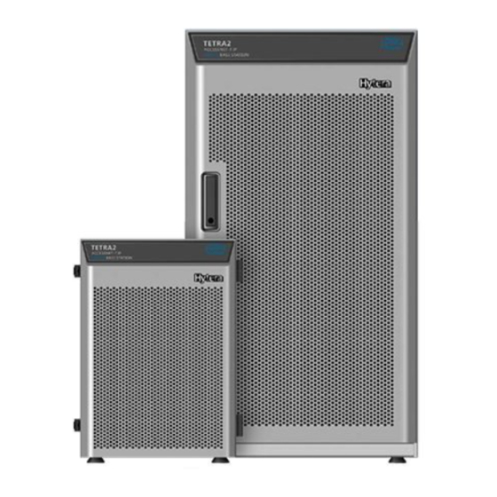
- Page 21 DIB-R5 advanced Product description Figure 5: DIB-R5 advanced (front view) Operation Manual 90DIBR5advancedOM02 - 1.0...
- Page 22 Product description DIB-R5 advanced Legend: DIB-R5 advanced (front view) Component Number Described in Ä Chapter 3.2.4.1 “RX FILTER” RX FILTER 1 to 3 on page 38 Ä Chapter 3.2.5.1 “DUPLEXER” DUPLEXER on page 40 Cable routing for Rx and GNSS cable (Global Navigation Satellite System, GNSS) TETRA Channel Unit (CHU)
- Page 23 DIB-R5 advanced Product description Figure 6: DIB-R5 advanced (top view) Legend: DIB-R5 advanced (top view) Component Number Described in Rear equipment rack door Lifting rings Cable fastening for voltage supply cable AC Power Distribution Module 1 to 2 Ä Chapter 3.2.2 “V (APDM) voltage supply”...
- Page 24 Product description DIB-R5 advanced Component Number Described in Ä Chapter 3.2.1.2 “Connec- Connection panel tion panel” on page 29 Ä Chapter 3.2.1.3 “GNSS GNSS splitter splitter” on page 31 TX/RXC RXC ‒ optional Front equipment rack door The following figure shows the rear view of the DIB-R5 advanced with opened equipment rack door.
- Page 25 DIB-R5 advanced Product description Figure 7: DIB-R5 advanced with opened equipment rack door (rear view) Operation Manual 90DIBR5advancedOM02 - 1.0...
-
Page 26: Characteristics Of The Dib-R5
Product description DIB-R5 advanced Characteristics of the DIB-R5 Legend: DIB-R5 advanced with opened equipment rack door (rear view) Component Number Described in Ä Chapter 3.2.2 “V AC Power Distribution Module 1 to 2 (APDM) voltage supply” on page 31 DC Power Distribution Module (DPDM) Ä... -
Page 27: Components
DIB-R5 advanced Product description Components 3.2 Components The following table lists the components of the DIB-R5 advanced. Components of the DIB-R5 advanced Component Described in Ä Connection and Ä On/off switch Ä Chapter 3.2.1.1 “On/ control panel off switch” on page 29 Ä... -
Page 28: Connection And Control Panel
Product description DIB-R5 advanced Components> Connection and control panel Component Described in Ä Cavity combiner Ä Chapter 3.2.10 “Cavity combiner” on page 51 Ä Backplane Ä Chapter 3.2.11 “Backplane” on page 52 3.2.1 Connection and control panel The DIB-R5 advanced features a connection and control panel at the top side to which the antenna and voltage supply cable can be connected conveniently from the top. -
Page 29: On/Off Switch
DIB-R5 advanced Product description Components> Connection and control panel Legend: Connection and control panel (top view) Component Description Ä Chapter 3.2.1.1 “On/off switch” On/off switch refer to on page 29 voltage supply Ä Chapter 3.2.2 “V voltage supply” on page 31 AC Power Distribution Module (APDM) Ä... - Page 30 Product description DIB-R5 advanced Components> Connection and control panel The connection panel is implemented by the alarm/connection box. The following figure shows the top view of the connection panel. The following table describes it in detail. Figure 9: Connection panel (top view) Legend: Connection panel (top view) Component Description...
-
Page 31: Gnss Splitter
DIB-R5 advanced Product description Components> VAC voltage supply Component Description Connector type Connection of the service com- RJ45 puter (local) Connection of service computer RJ45 (local) ‒ optional for controller redundancy This connection is required only if software downloads should be performed specifically for the redundant BSCU. - Page 32 Product description DIB-R5 advanced Components> VAC voltage supply Figure 10: APDM (top view) Legend: APDM (top view) Component Description Surge protection Surge Protection Device (SPD) of the DIB-R5 advanced On/off switch On/off switch of the DIB-R5 advanced Terminals Terminals for V input voltage The following figure shows the front view of the APDM.
-
Page 33: Power Supply Unit (Psu) Including Power Supply Module (Psm)
DIB-R5 advanced Product description Components> VAC voltage supply Figure 11: APDM (front view) Legend: APDM (front view) Component Description SPD ALARM Connection for monitoring the Surge Protection Device (SPD) Input Phase conductor connection for V input voltage Neutral conductor connection for V input voltage Earthing conductor connection for V... - Page 34 Product description DIB-R5 advanced Components> VAC voltage supply The following table describes the recommended number of PSMs depending on the voltage supply and the number of installed CHUs per equipment or compact rack. Recommended number of PSMs Voltage supply Number of CHUs Number of PSMs 90 V - 170 V...
-
Page 35: Vdc Voltage Supply
DIB-R5 advanced Product description Components> VDC voltage supply Legend: PSM (front view) Component Color Description green Lights if the V input voltage is OK Flashes if the V input voltage is outside the permissible voltage range green Lights if the V output voltage is OK Flashes if the V output voltage is overloaded... - Page 36 Product description DIB-R5 advanced Components> VDC voltage supply Figure 14: DPDM (top view) Legend: DPDM (top view) Component Description Surge protection Surge Protection Device (SPD) of the DIB-R5 advanced On/off switch On/off switch of the DIB-R5 advanced Terminals Terminals for V input voltage The following figure shows the front view of the DPDM.
-
Page 37: Divider Unit (Diu)
DIB-R5 advanced Product description Components> Divider Unit (DIU) Figure 15: DPDM (front view) Legend: DPDM (front view) Component Description SPD ALARM Connection for monitoring the Surge Pro- tection Device (SPD) DC INPUT -48V Connection for the negative voltage line (input voltage) Connection for the positive voltage line (input voltage) DC OUTPUT... -
Page 38: Rx Filter
Product description DIB-R5 advanced Components> Divider Unit (DIU) 3.2.4.1 RX FILTER The RX FILTER is used for receiving and repeating the received Rx signals. The Rx sig- nals are distributed by the RX FILTER and passed on to the respective Channel Units (CHU). -
Page 39: Passive Divider Unit (Pdu) - Only In Case Of A Chu Expansion
DIB-R5 advanced Product description Components> Divider Unit (DIU) Component Description Connector for the connection with CHU 4 Exp. BS Connector for the connection with a Passive Divider Unit (PDU) in a second equipment rack ‒ only in case of more than four CHUs Passive Divider Unit (PDU) ‒... -
Page 40: Transmitting Filter
Product description DIB-R5 advanced Components> Transmitting filter Legend: PDU (front view) Component Description Connector for the connection with CHU 1 Connector for the connection with CHU 2 Connector for the connection with CHU 3 Connector for the connection with CHU 4 RX-IN Connector for the connection with an RX FILTER in a second equipment rack ‒... -
Page 41: Tx Filter
DIB-R5 advanced Product description Components> Transmitting filter Legend: DUPLEXER (front view) Component Description Connector for the connection with CHU 1 Connector for the connection with CHU 2 Connector for the connection with CHU 3 Connector for the connection with CHU 4 Exp. -
Page 42: Tetra Channel Unit (Chu)
Product description DIB-R5 advanced Components> TETRA Channel Unit (CHU) 3.2.6 TETRA Channel Unit (CHU) The TETRA Channel Unit (CHU) is the transceiver module of the DIB-R5 and provides four radio channels for the voice and data transmission in transmitting and receiving direction (uplink and downlink) via one carrier signal. - Page 43 DIB-R5 advanced Product description Components> TETRA Channel Unit (CHU) Legend: CHU (front view) Component Description RX A Rx receiver input A RX B Rx receiver input B RX C Rx receiver input C OPEN TO TEST Connectors for test and service purposes, refer to Ä...
-
Page 44: Base Station Controller Unit (Bscu)
Product description DIB-R5 advanced Components> Base Station Controller Unit (BSCU) Figure 22: Indicators (LEDs) of the CHU Legend: Indicators (LEDs) of the CHU Color Description Lights in case of an error green Lights green if the transmitter of the CHU is switched on green Flashes if the CHU is in operation yellow... - Page 45 DIB-R5 advanced Product description Components> Base Station Controller Unit (BSCU) Figure 23: BSCU (front view) Operation Manual 90DIBR5advancedOM02 - 1.0...
- Page 46 Product description DIB-R5 advanced Components> Base Station Controller Unit (BSCU) Legend: BSCU (front view) Component Description GNSS GNSS antenna connector (SMA) Indicators (LEDs) Status display of the BSCU, refer to Ä Table “Legend: Indicators (LEDs) of the BSCU” on page 46 OPEN TO TEST Connectors for test and service purposes, refer to Ä...
- Page 47 DIB-R5 advanced Product description Components> Base Station Controller Unit (BSCU) Color Description green Lights if a connection exists between redundant BSCUs Flashes if data are being transferred green Lights if a connection exists to an Interconnection Relay Unit (IRU) ‒ only in the case of two equip- ment racks Flashes if data are being transferred The following figure shows the connectors for test and service purposes (OPEN TO...
-
Page 48: Interconnection Relay Unit (Iru) - Only In The Case Of A Chu Expansion
Product description DIB-R5 advanced Components> Interconnection Relay Unit (IRU) ‒ only in the case of a CHU expansion Component Description Connector type Mini-USB USB port for service purposes Mini-USB Reset button Reset button for restarting the integrated BSCU Mainboard (MCB) component 3.2.8 Interconnection Relay Unit (IRU) ‒... - Page 49 DIB-R5 advanced Product description Components> Interconnection Relay Unit (IRU) ‒ only in the case of a CHU expansion Figure 26: IRU (front view) Legend: IRU (front view) Component Description Indicators (LEDs) Status display of the IRU, refer to Ä Table “Legend: Indicators (LEDs) of the IRU”...
-
Page 50: Fan Unit
Product description DIB-R5 advanced Components> Fan unit Figure 27: Indicators (LEDs) of the IRU Legend: Indicators (LEDs) of the IRU Color Description green Flashes if the IRU is in operation Lights in case of an error CHU 1 to green Lights if connections to CHUs exist Flashes if data are being transferred 3.2.9 Fan unit... -
Page 51: Cavity Combiner
DIB-R5 advanced Product description Components> Cavity combiner The following figure shows the indicators (LEDs) of the fan unit. The following table describes it in detail. Figure 29: Indicators (LEDs) of the fan unit Legend: Indicators (LEDs) of the fan unit Color Description green... -
Page 52: Backplane
Product description DIB-R5 advanced Components> Backplane Figure 30: Cavity combiner (rear view) Legend: Cavity combiner (rear view) Component Description Connector for the connection with CHU 1 Connector for the connection with CHU 2 +12 V Voltage supply RS-485 Interface to backplane Tx transmitter output Connector for the connection with CHU 3 Connector for the connection with CHU 4... - Page 53 DIB-R5 advanced Product description Components> Backplane Figure 31: Backplane (rear view) Legend: Backplane (rear view) Component Description Connection for the positive voltage line (input voltage) DC -48V Connection for the negative voltage line (input voltage) Voltage supply connectors for the installed components Connectors of the connection panel, refer to Ä...
-
Page 54: Interfaces
Product description DIB-R5 advanced Interfaces Component Description SYNC1_IN Synchronization connector (input) for the second equipment rack ‒ only in case of more than four CHUs SYNC2_OUT Synchronization connector (output) of the first equipment rack ‒ only in case of more than four CHUs SYNC1_OUT Synchronization connector (output) of the first equipment rack ‒... -
Page 55: Wiring Diagrams
DIB-R5 advanced Product description Wiring diagrams State (configu- "active-open" rable) "active-close" Number Connection Plug for cable cross sections (wire or stranded wire) from 0.5 to 1.5 mm (28 to 14 AWG) Digital external alarm outputs Structure Relay State (configu- "active-open" rable) "active-close"... -
Page 56: Internal Wiring
Product description DIB-R5 advanced Wiring diagrams> Internal wiring Wiring diagram Described in Ä Antenna configura- Ä Antenna configuration with four Ä Antenna configura- tions CHUs and DUPLEXER tion with four CHUs and DUPLEXER Ä Antenna configuration with four Ä Chapter 3.4.3.2 CHUs and TX FILTER “Antenna configuration with four CHUs and TX... -
Page 57: Internal Wiring With Four Chus And Tx Filter
DIB-R5 advanced Product description Wiring diagrams> Internal wiring Figure 32: Internal wiring with four CHUs and DUPLEXER 3.4.1.2 Internal wiring with four CHUs and TX FILTER The following figure shows the internal wiring with four CHUs and TX FILTER. Figure 33: Internal wiring with four CHUs and TX FILTER Operation Manual 90DIBR5advancedOM02 - 1.0... -
Page 58: Wiring Of Two Equipment Racks - Only In The Case Of A Chu Expansion
Product description DIB-R5 advanced Wiring diagrams> Wiring of two equipment racks ‒ only in the case of a CHU expansion 3.4.2 Wiring of two equipment racks ‒ only in the case of a CHU expansion In case of a CHU expansion of the DIB-R5 advanced, two equipment racks positioned next to each other are used. -
Page 59: Antenna Configurations
DIB-R5 advanced Product description Wiring diagrams> Antenna configurations 3.4.3 Antenna configurations The following table provides an overview of the antenna configurations that are described in the following chapters. Overview of antenna configurations Antenna configuration Described in Ä Antenna configuration with four CHUs Ä... -
Page 60: Redundancy Options
Product description DIB-R5 advanced Redundancy options Figure 36: Antenna configuration with four CHUs and TX FILTER 3.5 Redundancy options ACCESSNET-T IP provides numerous redundancy concepts to ensure the availability of services and features reliably even in exceptional situations. The concept of designing system functions, function blocks, network elements and connection routes redundantly, may be required to ensure location reliability and system reliability. -
Page 61: Redundant Main Control Channel (Mcch)
DIB-R5 advanced Product description Redundancy options> Fallback operation The redundancy options can be combined with each other. 3.5.1 Redundant main control channel (MCCH) By redundant main control channels (MCCH) the operation of a base station is guaran- teed even if the carrier with the MCCH drops out or should be disturbed. If the carrier that provided the main control channel last drops out, an alternative carrier will take on this task. -
Page 62: Stand-Alone Operation
Product description DIB-R5 advanced Redundancy options> Redundant VAC voltage supply The connection to other network constituents is not possible in fallback operation, the fol- lowing services and features, however, are available locally: Group calls Individual calls (semi-duplex and duplex calls) Transmission of SDS and status messages Class 2 and class 3 air interface encryption (encrypted voice and data communica- tion) -
Page 63: Redundant Rectifier Modules (Power Supply Module, Psm)
DIB-R5 advanced Product description Redundancy options> Redundant synchronization (GNSS, PTP) 3.5.6.1 Redundant rectifier modules (Power Supply Module, PSM) The voltage supply continues to be ensured through redundant rectifier modules (Power Supply Module, PSM) and ensures the operation of DIB-R5 if one PSM should fail. The active and the redundant PSMs are all in operation in this case and divide the load among them. -
Page 64: Scope Of Delivery
Product description DIB-R5 advanced Scope of delivery 3.6 Scope of delivery The DIB-R5 advanced is delivered in a 19" equipment rack, in case of more than four CHUs in two 19" equipment racks. The scope of delivery varies depending on the variant. The variants of DIB-R5 advanced are the result of the following properties: Voltage supply Combiner... -
Page 65: Operation
DIB-R5 advanced Operation Safety measures and prerequisites 4 Operation This chapter describes the procedure for the proper operation of the product at its loca- tion. The work steps listed in the following table must be performed for the operation of the product. -
Page 66: Switching On The Dib-R5 Advanced
Operation DIB-R5 advanced Switching on the DIB-R5 advanced Relative humidity 5 % to 85 % (non-con- densing) Degree of protection IP20 Altitude for operation max. 4000 m (13 123 ft) Transport Temperature range -40 °C to +70 °C (-40 °F to +158 °F) (in original packaging) Storage... -
Page 67: Function Tests And Operating Surveillance
DIB-R5 advanced Operation Function tests and operating surveillance Performing function tests Following the execution of the work steps, it is recommended to perform function tests in order to ensure the proper mode of operation of the product. Ä Chapter 4.3 “Function tests and operating surveil- The function tests are described in lance”... -
Page 68: Work Equipment For Function Tests
Operation DIB-R5 advanced Function tests and operating surveillance > Connecting the service computer Work steps Described in Ä Checking standby carriers ‒ optional Ä Chapter 4.3.5 “Checking standby car- ‒ optional” riers on page 73 Ä Function tests and operating surveillance GNSS Ä... -
Page 69: Connecting The Service Computer
DIB-R5 advanced Operation Function tests and operating surveillance > Checking operating states The service computer is connected via the connection panel. The ethernet interface "SW1" is used by default for this purpose; with controller redundancy, the ethernet inter- face "SW2" is additionally used for the connection to the second BSCU. During the con- nection, the service computer is automatically assigned a local service IP address for the respective DIB-R5 advanced. -
Page 70: Checking Operating States
Operation DIB-R5 advanced Function tests and operating surveillance > Checking operating states Overview of the procedures for checking operating states Work step Described in Ä Checking operating states (via LEDs) Ä Chapter 4.3.3.1 “Checking operating states (via LEDs)” on page 70 Ä... -
Page 71: Checking Operating States (Via The Nmc-511 Faultmanager)
DIB-R5 advanced Operation Function tests and operating surveillance > Checking operating states 4.3.3.3 Checking operating states (via the NMC-511 FaultManager) Using the NMC‑511 FaultManager network management client, faults occurring in an ACCESSNET-T IP network can be detected and localized rapidly. This facilitates prompt fault elimination. -
Page 72: Checking The Availability
Operation DIB-R5 advanced Function tests and operating surveillance > Checking the availability 4.3.4 Checking the availability After network elements have been connected with an existing switch or router at the site, it must be checked whether the respective network element can be reached via the IP address of the BSCU. -
Page 73: Checking Standby Carriers - Optional
DIB-R5 advanced Operation Function tests and operating surveillance > Checking standby carriers ‒ optional Enter the following command to check the reachability of the network element: ping <xxx> <xxx> corresponds to the IP address of the respective component within the DIB-R5 advanced. -
Page 74: Function Tests And Operating Surveillance Gnss
Operation DIB-R5 advanced Function tests and operating surveillance > Function tests and operating surveillance GNSS Checking standby carriers Preparation: The respective DIB-R5 advanced must be in operation. The NMC-511 FaultManager must have been started. Select the corresponding operational carrier in the Equipment or Visualization view of the NMC-511 FaultManager. -
Page 75: Gnss Operational Monitoring (Via Nmc-511 Faultmanager)
DIB-R5 advanced Operation Function tests and operating surveillance > Function tests and operating surveillance GNSS Checking the installation site of the GNSS antenna Preparation: The installation and connection of the GNSS antenna must have been completed. Check the installation site of the GNSS antenna for proper condition, such as the fastening of the antenna mast, fastening of the GNSS antenna, cable routing. - Page 76 Operation DIB-R5 advanced Function tests and operating surveillance > Function tests and operating surveillance GNSS In the NMC-511 FaultManager the operating conditions and errors on network constitu- ents are represented by so-called alarm objects. Alarm objects provide alarms/statuses for properties of hardware and software compo- nents.
-
Page 77: Service Interruption
DIB-R5 advanced Service interruption Shutting down hardware components 5 Service interruption This chapter describes the procedure for the service interruption of the product. A service interruption may be required in the following cases: Work on an open equipment rack End of operation Malfunction The integration of further components, Possible restrictions for the operation... -
Page 78: Switching Off The Dib-R5 Advanced
Service interruption DIB-R5 advanced Switching off the DIB-R5 advanced Shutting down hardware components Press the Power button on the hardware component to shut it down. ð The software components are being shut down. The indicators (LEDs) go out after approx. 5 to 20 seconds. The hardware component is properly shut down if the "RUN"... - Page 79 DIB-R5 advanced Service interruption Switching off the DIB-R5 advanced Recommissioning The required recommissioning will be pointed out in the corresponding chapters. Operation Manual 90DIBR5advancedOM02 - 1.0...
- Page 80 Service interruption DIB-R5 advanced Switching off the DIB-R5 advanced Operation Manual 90DIBR5advancedOM02 - 1.0...
-
Page 81: Recommissioning
DIB-R5 advanced Recommissioning 6 Recommissioning To recommission the product, you either have to connect the equipment rack to the voltage source or switch it on, depending on the connection variant. Recommissioning Ä Chapter 4.2 For a new commissioning of DIB-R5 advanced, proceed as described in “Switching on the DIB-R5 advanced”... - Page 82 Recommissioning DIB-R5 advanced Operation Manual 90DIBR5advancedOM02 - 1.0...
-
Page 83: Maintenance
DIB-R5 advanced Maintenance Periodical visual inspections 7 Maintenance To ensure the proper operation of products, maintenance tasks and periodical visual inspections are required. The products have been designed for permanent and unsupervised operation. Neverthe- less you have to perform checks every now and then. When doing so, you can detect and remove dirt in the vicinity of or within equipment racks, so the air supply and heat dissipa- tion of the products is always ensured. - Page 84 Maintenance DIB-R5 advanced Periodical visual inspections Activities and intervals for visual inspections Task/s Interval/s Site inspection based on the document "DIB-R5 advanced Site Upon location Requirements", such as inspecting the: changes Once every Grounding equipment year Voltage supply connector TETRA antennas Installation location of the GNSS antenna Condition and fit of all supply lines, renew if necessary Connections between two DIB-R5 advanced ‒...
-
Page 85: Troubleshooting
DIB-R5 advanced Troubleshooting 8 Troubleshooting Troubleshooting via the network management system (NMS) The NMC-511 FaultManager can be used to detect faults within the ACCESSNET-T IP. This is done via a NMC computer that has been configured accordingly. The troubleshooting via the NMC-511 FaultManager should be performed prior to the troubleshooting on site (e.g. - Page 86 Troubleshooting DIB-R5 advanced Problem Possible cause Troubleshooting Switch/router defective Check operating state via LEDs on switch/router Call setup/registration not pos- Transmitting/receiving antenna Check antenna sible defective Cable connection defective Check wiring of antenna(s) incl. antenna cable Check internal wiring Carrier disabled Check status of carrier in the NMC-511 FaultManager Carrier incorrectly configured...
- Page 87 DIB-R5 advanced Troubleshooting Problem Possible cause Troubleshooting "ALM" LED is on Checking operating state in the NMC-511 FaultManager "FAN 1-6" LED flashes Checking operating state in the NMC-511 FaultManager Check fan Operation Manual 90DIBR5advancedOM02 - 1.0...
Need help?
Do you have a question about the ACCESSNET-T IP DIB-R5 advanced and is the answer not in the manual?
Questions and answers