
Related Manuals for Hytera DS-6250 U1


Summary of Contents for Hytera DS-6250 U1
- Page 1 DS-6250 U1 DMR Trunking Base Station User Guide Document Version: V1.0 Release Date: July 2017...
- Page 2 Copyright Information Hytera is the trademark or registered trademark of Hytera Communications Corporation Limited (the Company) in People's Republic of China (PRC) and/or other countries or areas. The Company retains the ownership of its trademarks and product names. All other trademarks and/or product names that may be used in this manual are properties of their respective owners.
-
Page 3: Table Of Contents
User Manual Contents Contents Documentation Information ........................1 1. Introduction ............................2 2. Getting Started ............................5 2.1 Appearance ............................5 2.2 Connectors and Interfaces ......................... 6 3. Installation ............................. 8 3.1 Safety Information ..........................8 3.2 Installation Flow ..........................9 3.3 Installation Requirements ........................ -
Page 4: Documentation Information
User Manual Documentation Information Documentation Information This section describes conventions, and revision history of this document. Audience This document is intended to be read by: Technical support engineers Maintenance engineers Installation and commissioning engineers Enterprise users Documentation Conventions Icon Conventions Icon... - Page 5 Documentation Information User Manual Revision History Document Version Product Version Release Date Description V1.0 August 2017 Release date. FCC Warning Any Changes or modifications not expressly approved by the party responsible for compliance could void the user’s authority to operate the equipment. This device complies with part 15 of the FCC Rules.
- Page 6 User Manual Introduction applicables aux appareils radio exempts de licence. L'exploitation est autorisée aux deux conditions suivantes: (1) l'appareil ne doit pas produire de brouillage, et (2) l'utilisateur de l'appareil doit accepter tout brouillage radioélectrique subi, même si le brouillage est susceptible d'en compromettre le fonctionnement.
-
Page 7: Introduction
Introduction User Manual 1. Introduction Integrated base station (iBS) is a new generation of base station supporting both narrow-band and wide-band communications. It integrates multiple functionalities performed by separate hardware units such as CHU, BSCU, DPU, and IRU into one hardware unit. iBS delivers stable signal coverage for a certain area and ensures smooth and continuous communication. -
Page 8: Getting Started
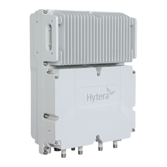
User Manual Getting Started 2. Getting Started 2.1 Appearance The figure below shows the overall appearance of iBS. Indicator Connector The figure below shows dimensions of iBS. 340mm 157.5mm... -
Page 9: Connectors And Interfaces
Getting Started User Manual 2.2 Connectors and Interfaces The figure below shows connectors and interfaces located on the bottom of the iBS. Mark Name Specification Description Antenna diversity Connected to diversity reception antenna RXD0 reception connector for receiving diversity RF signals. Antenna connector Connected to antenna for transmitting ANT0... - Page 10 User Manual Getting Started Mark Name Specification Description Connected to external transmission network. Transmission SFP1 Connected to optical-electric interface 1 conversion module, supports Gigabit Ethernet. SFP/SFP-F Supports SFP module. Supports single-mode optical fiber Transmission SFP0 (communication distance≤10km) and interface 0 multi-mode optical fiber (communication distance≤200km).
-
Page 11: Installation
Installation User Manual 3. Installation 3.1 Safety Information Before performing any operation, read the following precautions and operation instructions carefully to ward off potential risks. Local Laws and Regulations When operating a device, comply with the local safety laws and regulations. Power Supply Danger ... -
Page 12: Installation Flow
User Manual Installation Avoid dropping machinery and tools that may cause injury. Take sound safety actions such as wearing the hamlet and safety belt properly. Do wear heat-retaining clothes when working in cold areas. Make sure that the ladder is safe for use, and overload is strictly prohibited. ... -
Page 13: Tools
Installation User Manual It is recommended that the space of at least 500 mm be left between the product bottom and the ground. For product installed at its back, the space of at least 200 mm should be left at both left and right sides; for product installed at its left side, the space of at least 200 mm should be left in front and at back of product. -
Page 14: Materials
User Manual Installation Antistatic wrist strap, safety belt, helmet, safety rope, and slip-proof gloves. Safety Tool Wire stripper, wire crimper, and wire cutter. Cable Making Tool Multimeter, tape measure, level. Measuring Tool Fixed pulley, step ladder, marker pen, percussion drill, electrical tape, anti-UV Auxiliary Tool cable tie, label, screw kit, expansion screw, utility knife, heat gun, and duct tape. - Page 15 Installation User Manual 2. Place the auxiliary fixture onto the pole, insert four bolts into the auxiliary fixture and then tighten four nuts by using a torque wrench.
- Page 16 User Manual Installation 3. Secure the back panel onto the back of the iBS using four M6 screws. 4. Insert the back panel into the auxiliary fixture and tighten the captive fasteners on the back panel of iBS. Installing iBS at Left Side Installing iBS at left side and installing iBS at back are almost the same.
- Page 17 Installation User Manual 3.4.2.2 Installing iBS on a Wall You can install iBS on a wall at the back or left side of iBS. Installing iBS at Back 1. Place the auxiliary fixture on the wall at the installation position and then mark the anchor points by using a marking pen.
- Page 18 User Manual Installation 5. Insert the back panel into the auxiliary fixture and tighten the captive fasteners on the back panel of iBS. Installing iBS at Left Side Installing iBS at left side and installing iBS at back are almost the same. The only difference is that the back panel is secured to the left side rather than back of the iBS.
-
Page 19: Laying Out Cables
Installation User Manual 3.4.3 Laying out Cables 3.4.3.1 General Requirements Lay out cables according to requirements to reduce interference between them. Safety Requirements Lay out cables away from sharp objects or jagged walls, or protect cables using conduit. Lay out cables away from heat sources, or add heat-insulation materials between cables and heat sources. - Page 20 User Manual Installation Ground cables must be separated from signal cables to reduce interference between them. All metal components in the shell must be securely connected to the ground cable. Requirements for laying out optical fibers Do not bind optical fibers where they are bent. ...
- Page 21 Installation User Manual Antenna RF Antenna Ground Cable Power Cable GNSS Antenna Monitoring Cable Optical Fiber Cable External Transmission Device Power Supply External Monitoring Device GNSS Antenna 3.4.3.4 Installing Ground Cable 1. Make a ground cable having ring terminals with shrink tubing at both ends. The metal wires must be completed sealed, as shown in the figure below.
- Page 22 User Manual Installation 3.4.3.5 Installing Power Cable Note Power cable delivered with iBS is 2*12AWG cable having a maximum length of 60 meters. If distance between iBS and external power supply exceeds 60 meters, the cable diameter shall be increased accordingly. 1.
-
Page 23: Turning On/Off Ibs
Turning On/Off iBS User Manual 4. Turning On/Off iBS 4.1 Turning On iBS To turn on iBS, toggle the power switch on iBS to the ON position. 4.2 Turning Off iBS To turn off iBS, toggle the power switch on iBS to the OFF position. -
Page 24: Care And Cleaning
User Manual Care and Cleaning 5. Care and Cleaning To guarantee optimal performance as well as a long service life of the product, please follow the tips below. Caution Be sure to turn off the product before cleaning. Product Care ... -
Page 25: Specifications
Specifications User Guide 6. Specifications DS-6250 U1 specification Item Limit Frequency range RX: 400‐460MHz, TX: 410‐470MHz Operating voltage DC -48V Operating voltage range -37V/DC~-60V/DC ﹤550W Maximum power dissipation Bandwidth 5MHz Duplex Separation 10MHz General Channel Bandwidth 12.5K -40℃~+55℃ Operating temperature Storage temperature -40℃~+85℃... - Page 26 User Guide Specifications 30MHz ~ 1GHz ≤-57dBm 1GHz ~ 12.75GHz ≤-47dBm Output power 46dBm ±1.5dB Power Stability ≤0.01% FSK Bit Error ≤±1ppm Frequency error ≤8.5KHz Occupied Bandwidth ≤70dBc Intermodulation attenuation ≤60dBc Adjacent Channel adjacent Power Ratio channel(F0 ±12.5kHz) Transmitter ≤70dBc alternate channel(F0 ±25kHz)...
Need help?
Do you have a question about the DS-6250 U1 and is the answer not in the manual?
Questions and answers