Festo CP-FB11-E Programming Manual
Cp field bus node 11
Hide thumbs
Also See for CP-FB11-E:
- Brief description (62 pages) ,
- Brief description (62 pages) ,
- Brief description (62 pages)

Related Manuals for Festo CP-FB11-E


Summary of Contents for Festo CP-FB11-E
- Page 1 Compact performance Programming and diagnostics manual CP field bus node 11 Type CP−FB11−E Field bus protocol: − DeviceNet Manual 165 211 en 0802d [730 616]...
- Page 3 ....... . . 165 211 E (Festo AG & Co. KG, D 73726 Esslingen, Federal Republic of Germany, 2008) Internet: http://www.festo.com...
- Page 4 Contents and general instructions Festo P.BE−CP−FB11−E−EN en 0802d...
-
Page 5: Table Of Contents
..........3−7 Festo P.BE−CP−FB11−E−EN en 0802d... - Page 6 ..........A−5 A.2.1 Festo Output Object: Class Code 100d ......A−5 A.2.2...
-
Page 7: Designated Use
The CP field bus node type CP−FB11−E described in this man ual has been designed exclusively for use as a slave on the DeviceNet. CP modules from Festo can be connected to CP field bus node CP−FB11−E. The CP node may only be used as... -
Page 8: Service
Contents and general instructions Service Please consult your local Festo service centre if you have any technical problems. Notes on the use of this manual This manual contains specific information on installing, com missioning, programming and diagnosing CP field bus nodes FB11 for DeviceNet. -
Page 9: Important User Instructions
This means that failure to observe this instruction may result in damage to property. The following pictogram marks passages in the text which describe activities with electrostatically sensitive compo nents. Electrostatically sensitive components may be damaged if they are not handled correctly. Festo P.BE−CP−FB11−E−EN en 0802d... - Page 10 Accessories: Information on necessary or sensible accessories for the Festo product. Environment: Information on environment−friendly use of Festo products. Text markings The bullet indicates activities which may be carried out in any order. 1. Figures denote activities which must be carried out in the numerical order specified.
- Page 11 Ó Ó Ó Ó Ó Ó Ó Ó Ó Ó Ó Ó Ó Ó Ó Ó Ó Ô Ô Ô Ô Ô Ô Ô Ô Ô Ô Ô Ô Fig. 0/1: Manuals on the CP system Festo P.BE−CP−FB11−E−EN en 0802d...
- Page 12 Total number of I/O modules connected together on one CP connection String of the field bus node String assignment Total number of all the I/O modules connected via strings to a CP field bus node (0...3) Festo P.BE−CP−FB11−E−EN en 0802d...
-
Page 13: Installation
Installation Chapter 1 1−1 Festo P.BE−CP−FB11−E−EN en 0802d... - Page 14 Connecting the CP node to the field bus ......1−12 1−2 Festo P.BE−CP−FB11−E−EN en 0802d...
-
Page 15: General Instructions
You will then prevent the electronics in the node from being damaged. Instructions on connecting the power supply as well as gen eral information on installing CP modules can be found in the manual CP system". 1−3 Festo P.BE−CP−FB11−E−EN en 0802d... -
Page 16: Configuring The Cp System
BUS POWER DIL switch for set BUS STATUS ting the baud rate BUS ERR OR and compatibility with V1.4 24 V DC POWER POWER V SAVE ERROR Fig. 1/1: Position of switch 1−4 Festo P.BE−CP−FB11−E−EN en 0802d... -
Page 17: Setting The Station Number
Please note Station numbers may only be assigned once per module/ scanner. Recommendation: Assign the station numbers in ascending order. If necessary, assign the field bus addresses to suit the machine structure of your system. 1−5 Festo P.BE−CP−FB11−E−EN en 0802d... - Page 18 (example see Fig. 1/3). Setting for: Setting for: field bus address 05 field bus address 38 UNITS UNITS TENS TENS Fig. 1/3: Example of address settings 1−6 Festo P.BE−CP−FB11−E−EN en 0802d...
-
Page 19: Setting The Field Bus Baud Rate
Set the field bus baud rate on switch elements 1 and 2 as follows: Setting the field bus baud rate DIL switch 125 kBaud 250 kBaud 500 kBaud Fig. 1/4: Setting the field bus baud rate with switch elements 1 and 2 of the DIL switch 1−7 Festo P.BE−CP−FB11−E−EN en 0802d... -
Page 20: Setting Compatibility (Devicenet Configuration)
Version 1.4 Version 2.1 (until 01.02.2001) (as from 01.02.2001) (as supplied) Switch element 3 must always be set to ON. Fig. 1/5: Setting compatibility (DeviceNet configuration) with switch element 4 of the DIL switch 1−8 Festo P.BE−CP−FB11−E−EN en 0802d... - Page 21 Device type 25". Diagnostic bytes are not then available. If you wish to use a node with the current software version (as supplied): configure the CP system in your DeviceNet in accordance with chapter 2.2. 1−9 Festo P.BE−CP−FB11−E−EN en 0802d...
-
Page 22: Connecting Cp Modules
Connecting CP modules Warning S For connecting the CP modules to a string, use the special CP cable from Festo (type KVI−CP−1−...). S Please note that the total length of cable on a string must not exceed 10 m. You can thereby avoid:... - Page 23 Information on the procedure as well as on connecting cables and current requirements can be found in the manual CP system, installation and commissioning". 1−11 Festo P.BE−CP−FB11−E−EN en 0802d...
-
Page 24: Connecting The Cp Node To The Field Bus
50...100 m 0.75...3 m 250 kBaud 200 m 125 kBaud 500 m Not all the baud rates mentioned are supported by all con trollers, PLC/IPC. Note also any limitations in the maximum branch line length. 1−12 Festo P.BE−CP−FB11−E−EN en 0802d... - Page 25 Connection to the bus is made with a 5−pin M12 socket with PG9 screw connector. You can order these from Festo (type FBSD−GD−9−5POL, part no. 18324). Alternatively, you can use the bus cables of other manufacturers (see Appendix A).
- Page 26 BUS POWER MODULE STATUS I/O ERROR 24 V DC POWER POWER V SAVE ERROR Operating voltage Branch line for the bus interface T−adapter Field bus cables Bus cables Screening/shield Fig. 1/6: Structure of bus cables 1−14 Festo P.BE−CP−FB11−E−EN en 0802d...
- Page 27 Connect the field bus cables to the appropriate pins of the bus cable socket. Note also the connecting in structions in further diagrams, as well the instructions in the PLC manual for your controller. 1−15 Festo P.BE−CP−FB11−E−EN en 0802d...
- Page 28 1. Installation Pin assignment 1: Screening/shield 2: + 24 V Bus 3: GND Bus 4: Data + 5: Data − Node housing, functional earth Internal RC network Fig. 1/7: Pin assignment of the field bus interface 1−16 Festo P.BE−CP−FB11−E−EN en 0802d...
- Page 29 Pin assignment of the field bus interface on the node View Signal designations + 24 V Bus WHITE Data + BARE Screening/shield BLUE Data − BLACK GND Bus Fig. 1/8: Connection instructions for the DeviceNet 1−17 Festo P.BE−CP−FB11−E−EN en 0802d...
- Page 30 Terminating resistor Fig. 1/9: Terminating resistor in the socket of the field bus cable 2. Fit the bus cable socket onto the field bus plug. 1−18 Festo P.BE−CP−FB11−E−EN en 0802d...
-
Page 31: Commissioning
Commissioning Chapter 2 2−1 Festo P.BE−CP−FB11−E−EN en 0802d... - Page 32 ....2−10 2.2.4 Instructions on parametrizing with RSNetWorx for DeviceNet ... 2−11 2−2 Festo P.BE−CP−FB11−E−EN en 0802d...
- Page 33 CP system"). 2. Connect the CP modules (see manual CP system"). 3. Switch on the operating voltage. 4. Save the striing assignment by pressing the SAVE button. 5. Switch off the operating voltage for the node. 2−3 Festo P.BE−CP−FB11−E−EN en 0802d...
-
Page 34: Commissioning
16 input addresses and 16 output addresses. If no string is occupied, the node will respond to the field bus as standard with 2 occupied inputs and outputs (e.g. for test purposes). 2−4 Festo P.BE−CP−FB11−E−EN en 0802d... - Page 35 O = Output = Input Address range occupied by the CP system (last used string is string 3) ( ) = reserved address range (occupied or unused) Fig. 2/1: Address assignment of a CP system, example 2−5 Festo P.BE−CP−FB11−E−EN en 0802d...
-
Page 36: Switching On The Operating Voltage
If there is a separate supply for the control system and for the field bus slaves, the power should be switched on in the fol lowing sequence: 1. the power supply for all the field bus slaves 2. the power supply for the control system. 2−6 Festo P.BE−CP−FB11−E−EN en 0802d... -
Page 37: Commissioning And Addressing On The Devicenet
The following sections contain generally valid instructions on the configuration of the node on the DeviceNet. Detailed information can be found in the documentation or in the help for the configuration program you are using. 2−7 Festo P.BE−CP−FB11−E−EN en 0802d... -
Page 38: Configuring Devicenet Slaves (Eds)
EDS library": Installing an EDS library Entering the slave features by hand Installing an EDS library Current GSD files can be found on the Festo Internet pages under: www.festo.com/fieldbus You can obtain the GSD files and further configuration aids with the CD ROM Utilities" from Festo: type P.CD−VI−UTILITIES−2, part no. - Page 39 8 bytes / 8 bytes Product name CP−FB11−E Catalogue number 18227 When the EDS library has been extended, the node is entered in the slave list as a possible DeviceNet slave. It can now be added to a network. 2−9 Festo P.BE−CP−FB11−E−EN en 0802d...
-
Page 40: Valid Instructions For Parametrizing On The Devicenet
Specification of communication type. The following applies to node CP FB11−E: − Polled communication − Change of state / cyclic In addition to these communication connnections a Strobed I/O connection must be used in each case for the diagnosis. 2−10 Festo P.BE−CP−FB11−E−EN en 0802d... -
Page 41: Instructions On Parametrizing With Rsnetworx For Devicenet
EDS file. When the EDS file has been installed, the node is included in the list Hard ware". By pulling the cursor across, you can insert slaves in the network on the right−hand side. 2−11 Festo P.BE−CP−FB11−E−EN en 0802d... - Page 42 2. Commissioning Node type CP FB11−E in the list Hardware" Fig. 2/2: Hardware list and network in RSNetWorx for DeviceNet 2−12 Festo P.BE−CP−FB11−E−EN en 0802d...
- Page 43 A double click on the desired scanner in the network opens a dialogue field in which you can assign the available slaves to the scanner. Button for assigning the slave Fig. 2/3: Register card Scanlist" (example) 2−13 Festo P.BE−CP−FB11−E−EN en 0802d...
- Page 44 Fig. 2/4: Dialogue field Edit I/O parameters" The following applies to node CP FB11−E: The number of I/O bytes to be transmitted is fixed at 2 input bytes and 2 output bytes per CP string. 2−14 Festo P.BE−CP−FB11−E−EN en 0802d...
- Page 45 Assigning the I/O addresses of the slave With the register cards Output" and Input" you can assign the I/O addresses of the node to the PLC operands. Fig. 2/5: Address assignment of the input of the 4−byte diagnostic information (Strobed) 2−15 Festo P.BE−CP−FB11−E−EN en 0802d...
- Page 46 2. Commissioning Fig. 2/6: Address assignment of the input of the physical sensor signals (Polled) 2−16 Festo P.BE−CP−FB11−E−EN en 0802d...
- Page 47 Example: Scanner 1747−SDN (SLC 500 series) Valve terminal #12 with: 4 occupied strings: strings number 0, 1, 2 and 3 8 input bytes, input address as from I:004//00 8 output bytes, output address as from O:004/00 2−17 Festo P.BE−CP−FB11−E−EN en 0802d...
- Page 48 ( ) = reserved address range (occupied but unused) Fig. 2/8: Addressing example for scanner 1747−SDN (last used string is 3) Please note For access via the communication type explicit messag ing" the objects are described in Appendix A.2. 2−18 Festo P.BE−CP−FB11−E−EN en 0802d...
- Page 49 Diagnosis Chapter 3 3−1 Festo P.BE−CP−FB11−E−EN en 0802d...
- Page 50 ......3−15 Short circuit in the sensor supply at an input module ....3−16 3−2 Festo P.BE−CP−FB11−E−EN en 0802d...
-
Page 51: Diagnosis
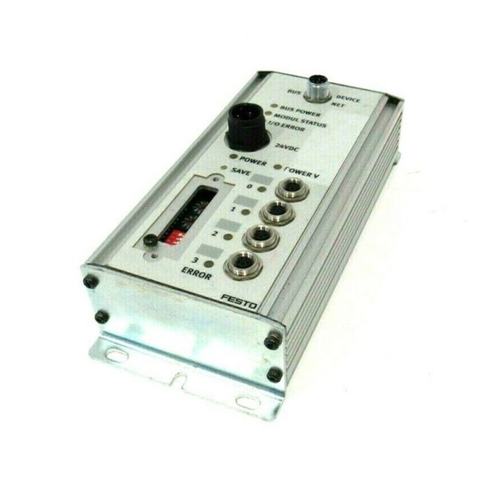
The LEDs on the node permit fast on−the−spot diagnosis. Bus LEDs Operating voltage LEDs String LEDs BUS POWER BUS STATUS BUS ERR OR 24 V DC POWER POWER V SAVE ERROR Fig. 3/1: LEDs of the CP node FB11 3−3 Festo P.BE−CP−FB11−E−EN en 0802d... - Page 52 2 (valves) 0...3 String error LEDs During the starting phase: ERROR flashes if the string assignment has been modified since the previous operation. During operation: lights up if a CP connection is inter rupted 3−4 Festo P.BE−CP−FB11−E−EN en 0802d...
-
Page 53: Normal Operating Status
In normal operating status the following LEDs on CP node 11 will light up: lights up; flashes; out) Operating status Error treatment BUS POWER Normal None MODULE STATUS BUS ERROR POWER POWER V 0...3 ERROR 3−5 Festo P.BE−CP−FB11−E−EN en 0802d... -
Page 54: Diagnostic Operating Voltage Power Or Power
CP valve terminal or output S Replace the CP module module defective POWER Operating voltage of the elelc S Check the operating voltage tronics (pin 1) not applied. connection POWER V Hardware error S Servicing required 3−6 Festo P.BE−CP−FB11−E−EN en 0802d... -
Page 55: Diagnostic Bus Leds
BUS STATUS Lights up once after switching None on (LED test) Node is ready for data ex S Start communication change, but has not yet been intialized by the master after having been switched on 3−7 Festo P.BE−CP−FB11−E−EN en 0802d... - Page 56 BUS ERROR Lights up once after switching S None on (LED test) Timeout expired, no valid S Check connection to PLC telegrams received within the timeout time, bus error, com munication error or loss of communication 3−8 Festo P.BE−CP−FB11−E−EN en 0802d...
-
Page 57: Testing The Valves
None of the programmed lockings or further switching conditions will be taken into account. Test routine During the test routine of the CP valve terminal, all the valves will be switched on and off at 1−second intervals. 3−9 Festo P.BE−CP−FB11−E−EN en 0802d... - Page 58 2. Set the address selector switch and the DIL switch elements to their original positions again. When the test routine is finished, switch on the power sup plies again. On the node On the output modules 3−10 Festo P.BE−CP−FB11−E−EN en 0802d...
-
Page 59: Reaction To Errors In The Control System
Unilaterally−actuated valves move to the basic position. Double−solenoid valves remain in the current position. Mid−position valves move to the mid−position and (depending on valve type) are pressurized, exhausted or blocked. 3−11 Festo P.BE−CP−FB11−E−EN en 0802d... -
Page 60: Diagnosis On The Devicenet
2. Double−click the icon of the valve terminal in the Software Configurator (e.g. RSNetworx). 3. Click the rider Device Parameters". 4. Double−click the parameter line Status word". Detailed information will be shown (see Fig. 3/2) Further information can be found in table Fig. 3/3. 3−12 Festo P.BE−CP−FB11−E−EN en 0802d... - Page 61 3. Diagnosis Fig. 3/2: Display of detailed information on diagnosis (explanations see text) 3−13 Festo P.BE−CP−FB11−E−EN en 0802d...
-
Page 62: Diagnosis Via User Program
(Fig. 3/3) is then available for the user program. The data from the Strobed I/O connec tion can be placed in the input file or in the M1 file of the con troller. 3−14 Festo P.BE−CP−FB11−E−EN en 0802d... -
Page 63: Short Circuit/Overload At An Output Module
CP system at will be reset automatically. the field bus node The outputs can then be used again. If the short circuit/over load still exists, the outputs will be switched off again. 3−15 Festo P.BE−CP−FB11−E−EN en 0802d... -
Page 64: Short Circuit In The Sensor Supply At An Input Module
CP connection at the CP input module briefly interrupt the operating voltage for the CP system at the field bus node. The inputs can then be used again. If the short circuit/over load still exists, the error will be shown again. 3−16 Festo P.BE−CP−FB11−E−EN en 0802d... - Page 65 Technical appendix Appendix A A−1 Festo P.BE−CP−FB11−E−EN en 0802d...
- Page 66 ..........A−5 A.2.1 Festo Output Object: Class Code 100d ......A−5 A.2.2...
-
Page 67: Technical Appendix
Pin 2, 3; bus interface External fuse required Rated value not protected against incorrect 24 V DC polarity + 4 % − 52 % (V 25 V, V 11.5 V) Tolerance Current consumption (at 24 V) 50 mA A−3 Festo P.BE−CP−FB11−E−EN en 0802d... - Page 68 Bridging time during drop in logic voltage 20 ms Electromagnetic compatibility Interference emitted Tested as per DIN EN 61000−6−4 (industry) Immunity against interference Tested as per DIN EN 61000−6−2 (industry) The component is intended for industrial use. A−4 Festo P.BE−CP−FB11−E−EN en 0802d...
-
Page 69: Devicenet Objects
A. Technical appendix DeviceNet objects A.2.1 Festo Output Object: Class Code 100d Vendor−specific object which contains the output information. Festo Output Object Class Attributes Attributes Access Name Type Value Get/set Output bytes Byte (2 bytes per string) A.2.2 Festo Input Object: Class Code 100d Vendor−specific object which contains the input information. - Page 70 A. Technical appendix A.2.3 Festo Diagnostic Object: Class Code 100d By means of this vendor−specific object (class code 102d) you can receive the device−related diagnostic information for the CP system. The information is grouped together in a diagnos tic byte for each string:...
-
Page 71: Accessories
A. Technical appendix Accessories www.festo.com/catalogue A−7 Festo P.BE−CP−FB11−E−EN en 0802d... - Page 72 A. Technical appendix A−8 Festo P.BE−CP−FB11−E−EN en 0802d...
- Page 73 Index Appendix B B−1 Festo P.BE−CP−FB11−E−EN en 0802d...
- Page 74 ............B−1 B−2 Festo P.BE−CP−FB11−E−EN en 0802d...
- Page 75 ....... 2−3 Preparations for commissioning ....2−3 B−3 Festo P.BE−CP−FB11−E−EN en 0802d...
- Page 76 ......1−18 Important user instructions ......B−4 Festo P.BE−CP−FB11−E−EN en 0802d...
- Page 77 ........3−6 B−5 Festo P.BE−CP−FB11−E−EN en 0802d...
- Page 78 ........B−6 Festo P.BE−CP−FB11−E−EN en 0802d...
Need help?
Do you have a question about the CP-FB11-E and is the answer not in the manual?
Questions and answers