Festo CP-FB13-E Programming And Diagnosing Manual
Cp field bus node13
Hide thumbs
Also See for CP-FB13-E:
- Manual (112 pages) ,
- Programming and diagnostics manual (110 pages) ,
- Brief description (64 pages)

Subscribe to Our Youtube Channel
Related Manuals for Festo CP-FB13-E


Summary of Contents for Festo CP-FB13-E
- Page 1 Compact Performance Manual Programming and diagnosing CP field bus node 13 Type CP−FB13−E Field bus connection PROFIBUS−DP as per EN 50170 Manual 165 213 en 0802h [730 623]...
- Page 3 ....... . . 165 213 E (Festo AG & Co. KG, D 73726 Esslingen, Federal Republic of Germany, 2008) Internet: http://www.festo.com...
- Page 4 Contents and general instructions Festo P.BE−CP−FB13−E−EN en 0802h...
-
Page 5: Table Of Contents
Normal operating status ........3−4 Festo P.BE−CP−FB13−E−EN en 0802h... - Page 6 ............B−1 Festo P.BE−CP−FB13−E−EN en 0802h...
-
Page 7: Designated Use
The CP field bus node type CP−FB13−E described in this man ual has been designed exclusively for use as a slave on the PROFIBUS−DP. CP modules from Festo can be connected to CP field bus node CP−FB13−E. The CP node may only be used as follows: as specified in industrial applications. -
Page 8: Target Group
PROFIBUS−DP slaves. Service Please consult your local Festo repair service if you have any technical problems. Notes on the use of this manual This manual contains specific information on installing, com missioning, programming and diagnosingCP field bus node FB13 for PROFIBUS−DP in accordance with EN 50170. -
Page 9: Important User Instructions
This means that failure to observe this instruction may result in damage to property. The following pictogram marks passages in the text which describe activities with electrostatically sensitive compo nents. Electrostatically sensitive components may be damaged if they are not handled correctly. Festo P.BE−CP−FB13−E−EN en 0802h... - Page 10 Accessories: Information on necessary or sensible accessories for the Festo product. Environment: Information on environment−friendly use of Festo products. Text markings The bullet indicates activities which may be carried out in · any order. 1. Figures denote activities which must be carried out in the numerical order specified.
- Page 11 Ó Ó Ó Ó Ó Ó Ó Ó Ó Ó Ó Ó Ó Ó Ó Ó Ó Ô Ô Ô Ô Ô Ô Ô Ô Ô Ô Ô Ô Tab. 0/1: Manuals on the CP system Festo P.BE−CP−FB13−E−EN en 0802h...
- Page 12 LEDs. String Total number of I/O modules connected together on one CP connection of the field bus node String assignment Total number of all I/O modules connected via strings to a CP field bus node (0...3) Festo P.BE−CP−FB13−E−EN en 0802h...
-
Page 13: Installation
Installation Chapter 1 1−1 Festo P.BE−CP−FB13−E−EN en 0802h... - Page 14 ........1−19 1−2 Festo P.BE−CP−FB13−E−EN en 0802h...
-
Page 15: General Instructions On Installation
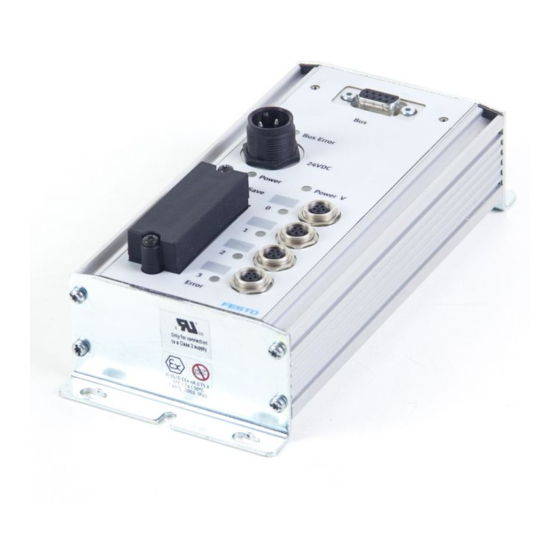
Observe the regulations for handling electrostatically · sensitive components. You will then prevent the electronics in the node from being damaged. General information on installing the CP modules can be found in the manual Installing and commissioning CP systems." 1−3 Festo P.BE−CP−FB13−E−EN en 0802h... - Page 16 24 V DC Identification fields POWER POWER V SAVE Rotary and DIL switches Cover of the rotary/DIL switches SAVE button ERROR Connection for power supply Fig. 1/1: Connecting and display elements of the CP field bus node 1−4 Festo P.BE−CP−FB13−E−EN en 0802h...
-
Page 17: Configuring The Field Bus Node
With the rotary and DIL switches you can set the following functions: the station number the voltage monitoring the field bus protocol PROFIBUS−DP: Switch elements 3...6 are reserved and must be set to the positions specified below. 1−5 Festo P.BE−CP−FB13−E−EN en 0802h... - Page 18 2. Assign an unused PROFIBUS address to the field bus node. 3. Use a screwdriver to set the arrow of the relevant rotary switch or element 1 of the DIL switch to the units, tens or hundreds figure of the desired station number. 1−6 Festo P.BE−CP−FB13−E−EN en 0802h...
- Page 19 Observe any possible limitations as regards the assign ment of station addresses by your DP master. Recommendation: Assign the station numbers in ascending order. If necessary, assign the station numbers to suit the machine structure of your system. 1−7 Festo P.BE−CP−FB13−E−EN en 0802h...
- Page 20 Setting the voltage monitoring, DIL switch element 2 Reserved DIL switch elements 3...6 Leave switch elements 3...6 set as follows: DIL switch Setting reserved DIL 3...5: ON DIL 6: OFF Tab. 1/3: Reserved DIL switch elements 3...6 1−8 Festo P.BE−CP−FB13−E−EN en 0802h...
-
Page 21: Connecting The Field Bus
If the CP system is fitted onto the moving part of a ma chine, the field bus cable on the moving part must be pro vided with strain relief. Please observe the relevant regula tions in IEC/DIN EN 60204−1. 1−9 Festo P.BE−CP−FB13−E−EN en 0802h... - Page 22 < 110 ohms/km Core diameter: > 0.64 mm Core cross−sectional area: > 0.34 mm Bus length Exact specifications on the bus length can be found in the next section and in the manuals for your control system. 1−10 Festo P.BE−CP−FB13−E−EN en 0802h...
-
Page 23: Field Bus Baud Rate And Field Bus Length
100 m 187.5 1000 m 33.3 m 400 m 20 m 1500 200 m 6.6 m 3000...12000 100 m Tab. 1/4: Max. field bus length and branch line length for PROFIBUS−DP depending on the baud rate 1−11 Festo P.BE−CP−FB13−E−EN en 0802h... -
Page 24: Field Bus Interface
Festo type FBS−SUB−9−GS−DP−B. Please note Only the Festo field bus plug complies with IP65. Before connecting field bus plugs from other manufacturers: replace the two flat screws by bolts (part no. 340960). ·... -
Page 25: Connection Possibilities
Clamp strap for screening/shield connection Field bus incoming (IN) Switch for bus termination and continuing field Field bus continuing (OUT) Only connected capacitively Fig. 1/3: Field bus plug from Festo type FBS−SUB−9−GS−DP−B 1−13 Festo P.BE−CP−FB13−E−EN en 0802h... - Page 26 1. Installation Please note The clamp strap in the field bus plug from Festo is con nected internally only capacitively with the metallic hous ing of the sub−D plug. This is to prevent equalizing currents flowing through the screening of the field bus cable.
- Page 27 5. FE: Functional earth Housing/thread: Screening/shield Bus out Bus in Protective cap or plug with bus termination resistor if connection is not used. Tab. 1/6: Pin assignment of the field bus interface with adapter for M12 connection, 5−pin 1−15 Festo P.BE−CP−FB13−E−EN en 0802h...
- Page 28 Siemens Optical Link Module (OLM) for PROFIBUS plus Siemens Optical Link Plug (OLP) for PROFIBUS (IP20) ® Harting Han−InduNet Media converter IP65 in combina tion with adapter cable for Festo products (optical data transmission in DESINA installation concept) 1−16 Festo P.BE−CP−FB13−E−EN en 0802h...
-
Page 29: Bus Termination With Terminating Resistors
Fit a bus termination to both ends of a bus segment. · Recommendation: Use the ready−to−use field bus plugs from Festo for the bus termination. A suitable resistor network is incorporated in the housing of this plug (see Fig. 1/4). -
Page 30: Connecting The Cp Modules
Connecting the CP modules Warning For connecting the CP modules to a string, use the · special CP cable from Festo (type KVI−CP−1−...). Please note that the total length of cable on a string · must not exceed 10 m. -
Page 31: Connecting The Power Supply
EMERGENCY STOP (e.g. switching off the operating voltage for the valves and output modules, switching off the com pressed air). 1−19 Festo P.BE−CP−FB13−E−EN en 0802h... - Page 32 1. Installation 1−20 Festo P.BE−CP−FB13−E−EN en 0802h...
-
Page 33: Commissioning
Commissioning Chapter 2 2−1 Festo P.BE−CP−FB13−E−EN en 0802h... -
Page 34: Information On Commissioning
........2−20 2.3.3 Commissioning the CP system on the PROFIBUS−DP ... 2−24 2−2 Festo P.BE−CP−FB13−E−EN en 0802h... - Page 35 1. Connect the power supply of the node (see manual Installing and commissioning CP systems"). 2. Connect the CP modules. 3. Switch on the power supply. 4. Save the current string assignment by pressing the SAVE button. 2−3 Festo P.BE−CP−FB13−E−EN en 0802h...
- Page 36 2. Commissioning SAVE button 24 V DC POWER POWER V SAVE ERROR Fig. 2/1: The SAVE button saves the current string assignment of the CP system as the NOMINAL configuration 2−4 Festo P.BE−CP−FB13−E−EN en 0802h...
- Page 37 All the outputs of the CP system will be frozen." The CP sys tem now no longer reacts to modifications to the output image in the master. With each further SYNC command, the updated output image will be transmitted. Return to normal operation: UNFREEZE command 2−5 Festo P.BE−CP−FB13−E−EN en 0802h...
- Page 38 There are two possibilities of configuring the CP system: standard mode compact mode The CP system recognises automatically the mode in which you wish to operate the CP system, on the basis of the DP identifier sent by the master. 2−6 Festo P.BE−CP−FB13−E−EN en 0802h...
- Page 39 = input/output Length = byte = word Consistency = byte or word = complete length Not supported Fig. 2/2: Structure of the identifier byte Example: 00010000 = 016 (010 ): 8DI = 8 digital inputs 2−7 Festo P.BE−CP−FB13−E−EN en 0802h...
- Page 40 16DX Input module and output module of string 0 16DX Input module and output module of string 1 16DX Input module and output module of string 2 Tab. 2/2: Example of configuration in standard mode 2−8 Festo P.BE−CP−FB13−E−EN en 0802h...
- Page 41 Non−existent CP valve terminals occupy input or output bytes if a higher string is assigned with inputs or outputs. Maximum configuration in compact mode: 8 input bytes and 8 output bytes 2−9 Festo P.BE−CP−FB13−E−EN en 0802h...
- Page 42 16DI 32DI With output modules or valve terminals Last used string Number of Sum identifier (decimal) number output bytes 16DO 32DO Tab. 2/3: Compact mode: possible configuration of the inputs and outputs 2−10 Festo P.BE−CP−FB13−E−EN en 0802h...
- Page 43 3 output modules, highest assigned string number = 2. DP identifier Comment 6 bytes inputs 6 bytes outputs Example 2: CP system with 3 strings, only 3 output modules, highest assigned string number = 2. DP identifier Comment 6 bytes outputs 2−11 Festo P.BE−CP−FB13−E−EN en 0802h...
- Page 44 (Ident. number, Revision, etc.), the device master file (GSD) also contains a selection of ident ifiers. Reference sources Current GSD files can be found on the Festo Internet pages under: www.festo.com/fieldbus You can obtain the GSD files and further configuration aids with the CD ROM Utilities"...
- Page 45 The configuration of the CP system requires a very accurate procedure, as different configuration specifications are some times required for each system, due to the modular structure. Please observe here the specifications in the following sec tions. 2−13 Festo P.BE−CP−FB13−E−EN en 0802h...
- Page 46 As from STEP 7 V4.02, GSDs are stored within the STEP 7 project (station GSD). This can cause the updating/reading of new GSD files to appear as if incorrect. Please inform yourself about handling the station GSD files in the STEP 7 help. 2−14 Festo P.BE−CP−FB13−E−EN en 0802h...
- Page 47 4. Insert a DP master system: Right−hand mouse click on DP" under CPU" in the rack. Click on [Add master system] in the context menu. The line of the DP master system will be displayed. 2−15 Festo P.BE−CP−FB13−E−EN en 0802h...
- Page 48 \PROFIBUS−DP\Additional Field Devices\Valves." The folder VALVES is displayed when you copy the GSD (see step 1 of the preparations). Pull the station type FESTO CP FB13" onto the line of the DP master system 2. The dialogue window Properties PROFIBUS interface"...
- Page 49 2. Commissioning Fig. 2/3: Station selection with STEP 7 HW Config (the windows displayed are not all visible at the same time, see text) 2−17 Festo P.BE−CP−FB13−E−EN en 0802h...
- Page 50 1. Click on the icon of the valve terminal to be configured in Hardware config. (see Fig. 2/4 1). The configuration table will be displayed under the rack 2. 2. Open the module FESTO CP FB13" (folder\PROFIBUS− DP\Additional Field Devices\Valves\...) in the hardware catalogue 3.
- Page 51 2. Commissioning Fig. 2/4: Configuration in standard mode with STEP 7 HW Config Fig. 2/5: Configuration in compact mode with STEP 7 HW Config 2−19 Festo P.BE−CP−FB13−E−EN en 0802h...
- Page 52 (I22.0...23.7, (unused) String 2: 16 outputs and O24.0...25.7 16 electrical inputs I24.0...25.7 String 3: Address range can be not assigned used for other bus slaves Tab. 2/5: Addressing the CP system shown in Fig. 2/6 2−20 Festo P.BE−CP−FB13−E−EN en 0802h...
- Page 53 Octet 6: Bits 0...7 I25.0...I25.7 I = Input O = Output ( ) = Assigned, but not used Fig. 2/6: Examples of addressing the inputs and outputs of a CP system on the PROFIBUS−DP in standard mode 2−21 Festo P.BE−CP−FB13−E−EN en 0802h...
- Page 54 String 1: (O22.0...23.7, unused) 16 inputs I22.0...23.7 String 2: O24.0...25.7 16 outputs String 3: not assigned Address range can be used for other bus slaves Tab. 2/6: Addressing the CP system shown in Fig. 2/7 2−22 Festo P.BE−CP−FB13−E−EN en 0802h...
- Page 55 ( ) = Assigned, but not used Sum of the assigned bytes: 6 output bytes; 4 input bytes Fig. 2/7: Addressing the inputs and outputs of a CP system on the PROFIBUS−DP in compact mode 2−23 Festo P.BE−CP−FB13−E−EN en 0802h...
- Page 56 NOMINAL configuration are com plete and correct (see also section 2.1.1). the power supply for the programmable logic controller and for the field bus slaves is switched on eithersimulta neously or in the sequence indicated above. 2−24 Festo P.BE−CP−FB13−E−EN en 0802h...
- Page 57 (pins 1 and 2), but without compressed air. A suitable test function is therefore available which does not trigger unde sired reactions. Please note A CP valve location occupies two addresses. The following assignment applies: lower−value address: pilot solenoid 14 higher−value address: pilot solenoid 12 2−25 Festo P.BE−CP−FB13−E−EN en 0802h...
- Page 58 2. Commissioning 2−26 Festo P.BE−CP−FB13−E−EN en 0802h...
-
Page 59: Diagnosis And Error Treatment
Diagnosis and error treatment Chapter 3 3−1 Festo P.BE−CP−FB13−E−EN en 0802h... - Page 60 ......... . . 3−24 3−2 Festo P.BE−CP−FB13−E−EN en 0802h...
-
Page 61: Diagnosis And Error Treatment
CP system. LED BUS ERROR LED POWER LED POWER V PROFIBUS−DP String fault LEDs BUS ERROR 24 V DC POWER POWER V SAVE ERROR Fig. 3/1: LEDs of CP field bus node FB13 3−3 Festo P.BE−CP−FB13−E−EN en 0802h... -
Page 62: Normal Operating Status
In the normal operating status only the green LEDs POWER and POWER V light up. lights up LED flashes Colour Operating status Fault treatment Normal None POWER Green Normal None lights up POWER V Green Normal None lights up Tab. 3/2: Normal operating status 3−4 Festo P.BE−CP−FB13−E−EN en 0802h... -
Page 63: Fault Display Of The Power Leds
(pin 2) not in the tolerance range. outputs (pin 2). Green POWER V flashes Operating voltage of the Check the operating voltage · POWER electronics (pin 1) not applied. connection Hardware fault Servicing required 3−5 Festo P.BE−CP−FB13−E−EN en 0802h... -
Page 64: Fault Messages Of The Led Bus Error
Field bus module switched off Field bus module · or defective Interrupted, short−circuited or Field bus connection · faulty field bus connection Configuration not correct: Configuration · nominal actual status Valve test ERROR (Conclude valve test) 3−6 Festo P.BE−CP−FB13−E−EN en 0802h... -
Page 65: Testing The Valves
All valves are switched on/off cyclically. None of the programmed lockings or further switching conditions will be taken into account. Test routine During the test routine of the CP terminal all the valves are switched on/off at 1−second intervals. 3−7 Festo P.BE−CP−FB13−E−EN en 0802h... - Page 66 2. Set the address selector switch and the DIL switch elements to their original positions again. When the test routine is finished, switch on the power sup plies again: on the node on the output modules. 3−8 Festo P.BE−CP−FB13−E−EN en 0802h...
-
Page 67: Diagnosis Via Profibus−Dp
Interruption of the CP connection on various CP modules Additional fault messages when DIL switch element 2 = ON: Load voltage failure in the CP connection Lower voltage tolerance limit of CP valves exceeded (t 20.4 V) 3−9 Festo P.BE−CP−FB13−E−EN en 0802h... -
Page 68: Diagnostic Steps
CP system. Only the diagnostic bits, which require a further diagnostic step, are represented. Station status 1 Device−related diagnosis 1 sensible Device−related diagnosis 1 Device−related diagnosis 2...5 can be read Fig. 3/2: Diagnostic steps 3−10 Festo P.BE−CP−FB13−E−EN en 0802h... -
Page 69: Overview Of Diagnostic Bytes
3.3.3 Overview of diagnostic bytes Diagnostic words Several diagnostic words are provided for each bus slave. The diagnostic words and their meaning for CP systems from Festo are shown in the following table: Byte Octet Diagnostic address Diagnostic address + 1... -
Page 70: Details For Standard Diagnostic Information
1 = CP system does not support the function requested Diag.Invalid_Slave_Response Always 0 (set by CP system) Diag.Prm_Fault Last parametrizing telegram faulty Diag.Master_Lock Always 0 (set by CP system) bold = Valve terminal related bits Tab. 3/4: Diagnostic bits station status 1 3−12 Festo P.BE−CP−FB13−E−EN en 0802h... - Page 71 = Valve terminal related bits Tab. 3/5: Diagnostic bits of station status 2 Octet 3: Station status_3 Meaning Explanation 0...6 Reserved Diag.Ext_Diag_Overflow Always 0 (set by CP system) Tab. 3/6: Diagnostic bits of station status 3 3−13 Festo P.BE−CP−FB13−E−EN en 0802h...
- Page 72 5...6 Ident_number Manufacturer identification: These octets contain the manufacturer identification: F13C for the Festo CP system. Ext_Diag_Data Header device−related diagnosis: (device−related diagnosis) The CP system enters the fixed value 8 in this octet, i.e. 8 Octets Device−related diagnosis" incl. the header octet, are made available/transferred, irre spective of the equipment fitted on the CP system.
- Page 73 Common fault 1 1 = Fault in string 1 Common fault 2 1 = Fault in string 2 Common fault 3 1 = Fault in string 3 Tab. 3/8: Diagnostic bits of device−related diagnosis 1 3−15 Festo P.BE−CP−FB13−E−EN en 0802h...
- Page 74 = Load voltage of valve coils t20.4 V = Load voltage of valve coils t10 V load Not used Only with setting DIL switch element 2 at ON Tab. 3/10: Diagnostic bits device−related diagnosis 2...5 3−16 Festo P.BE−CP−FB13−E−EN en 0802h...
-
Page 75: Fault Treatment
PLC stop, field bus interruption or field bus fault: Single−solenoid valves move to the basic position. Double−solenoid valves remain in the current position. Mid−position valves move to the mid−position (depend ing on valve type: pressurized, exhausted or blocked). 3−17 Festo P.BE−CP−FB13−E−EN en 0802h... -
Page 76: Siemens Simatic
Reaction to failure of a DP slave Default OM is programmed QVZ: Quitting delay; OM: Organisation module; PEU: Periphery not clear Tab. 3/11: Fault reactions STOP and RUN with S5/S7 Further details can be found in the relevant controller manuals. 3−18 Festo P.BE−CP−FB13−E−EN en 0802h... - Page 77 = 03FE (see mask Properties DP slave" in HW Config) RET_VAL:=MW100 If fault occurs, output fault code RECORD:=P#M110.0 WORD 7 Pointer at start of data range for diagnosis and length of diagnostic data BUSY:=M10.0 Reading concluded 3−19 Festo P.BE−CP−FB13−E−EN en 0802h...
-
Page 78: Online Diagnosis With Step
3. Diagnosis and error treatment Online diagnosis with STEP 7 Direct diagnostic events in conjunction with the Festo valve terminal can be: Decentral periphery: station failure Communication between slave and master interrupted Faulty component (see device−specific diagnosis) Transition of the operating status from START to RUN... - Page 79 Fig. 3/3: Online diagnosis via diagnostic buffer (explanation see text) Device−related diagnosis Instead of the CPU, click on the CP valve terminal 6. · Read further information on the device−related diagnosis of the CP system via the window Component status." 3−21 Festo P.BE−CP−FB13−E−EN en 0802h...
-
Page 80: Short Circuit/Overload
9...12 Device− related diagnosis 2...5" will be set to 1. Please note The outputs cannot be used again until the short circuit or overload has been eliminated and the fault deleted. 3−22 Festo P.BE−CP−FB13−E−EN en 0802h... - Page 81 C ill b · CP system automatically Tab. 3/13: Deleting the fault possibilities The outputs can then be used again. If the short circuit/over load still exists, the outputs will be switched off again. 3−23 Festo P.BE−CP−FB13−E−EN en 0802h...
-
Page 82: Input Module
The inputs can then be scanned again. If the short circuit/ overload still exists, the fault will be shown again. Module CP−E16−M8−Z: The short circuit/overload will be reset automatically and the voltage will be switched on again. 3−24 Festo P.BE−CP−FB13−E−EN en 0802h... - Page 83 Technical appendix Appendix A A−1 Festo P.BE−CP−FB13−E−EN en 0802h...
-
Page 84: A. Technical Appendix
......A−12 A.2.8 Transmission times on the PROFIBUS−DP ....A−12 A−2 Festo P.BE−CP−FB13−E−EN en 0802h... -
Page 85: Technical Appendix
Current consumption Pin 1 node FB13−E 250 mA Complete electronics of the CP system See manual CP system," current consumption table Residual ripple 4 Vpp (within tolerance) Bridging time during drop in logic voltage 20 ms A−3 Festo P.BE−CP−FB13−E−EN en 0802h... - Page 86 PROFIBUS−DP as per EN 50170 Design RS 485, floating Transmission type Serial asynchronous, half−duplex Baud rate 9.6 ... 12000 kBaud, automatic baud rate recognition Cable type Depending on cable length and baud rate: see controller manual A−4 Festo P.BE−CP−FB13−E−EN en 0802h...
-
Page 87: Commissioning With The General Dp Master
A. Technical appendix Commissioning with the general DP master The Festo CP system can be controlled from any PLC, PC or industrial PC with a PROFIBUS−DP modulein accordance with EN 50170. Further information Read the information on the following themes in the... -
Page 88: Send Parametriziung Data
Explanation Unlock_Req Lock_Req min T + slave parameter may be overwritten CP system released for other masters CP system blocked for other masters CP system released for other masters Tab. A/1: Octet 1: Station status A−6 Festo P.BE−CP−FB13−E−EN en 0802h... -
Page 89: A.2.3 Check The Configuration Data
DP identifier for inputs and outputs via sum identifier: sum of the input bytes and sum of the output bytes. The composition of the identifier bytes can be found in section 2.1.2. A−7 Festo P.BE−CP−FB13−E−EN en 0802h... - Page 90 A. Technical appendix Summary of parameters (Chk_Cfg): Octet 1−n: DP identifier Permitted identifiers for CP systems from Festo in compact mode (see also Tab. 2/3): Number of Decimal inputs Decimal outputs I/Os up to 16 up to 32 up to 48 up to 64 Tab.
-
Page 91: Transferring Input And Output Data
Please note With the function Data_Exchange, the CP system expects the output data for the valves and electric outputs. The input data is sent to the master as a reply telegram. A−9 Festo P.BE−CP−FB13−E−EN en 0802h... - Page 92 Bit 7: Input/output z+7 . . . Octet 8: I/O data byte_7 Bit 0: Input/output t+8 Bit 1: Input/output t+9 . . . Bit 7: Input/output t+15 x, y, z, t = Address offset of the master module A−10 Festo P.BE−CP−FB13−E−EN en 0802h...
-
Page 93: Implemented Functions And Service Access Points (Sap
(e.g. if there is a bus failure). A.2.6 Implemented functions and service access points (SAP) Function Available Destination SAP (DSAP) Data_Exchange RD_Inp RD_Outp Slave_Diag Set_Prm Chk_Cfg Get_Cfg Global_Control Set_Slave_Add Tab. A/5: Overview of implemented functions and service access points A−11 Festo P.BE−CP−FB13−E−EN en 0802h... -
Page 94: Bus Parameters/Reaction Times
< 2 ms. Please refer to the manual for your controller for ascertaining the total time required for transmission. Please note Observe here the cycle time of your PLC and the update time of the PROFIBUS−DP. A−12 Festo P.BE−CP−FB13−E−EN en 0802h... - Page 95 Index Appendix B B−1 Festo P.BE−CP−FB13−E−EN en 0802h...
-
Page 96: B. Index
............B−3 B−2 Festo P.BE−CP−FB13−E−EN en 0802h... - Page 97 ......3−15 Device−related diagnosis 2...5 ..... 3−16 B−3 Festo P.BE−CP−FB13−E−EN en 0802h...
- Page 98 ......... . 3−3 B−4 Festo P.BE−CP−FB13−E−EN en 0802h...
- Page 99 ........2−4 B−5 Festo P.BE−CP−FB13−E−EN en 0802h...
- Page 100 ........VIII B−6 Festo P.BE−CP−FB13−E−EN en 0802h...
Need help?
Do you have a question about the CP-FB13-E and is the answer not in the manual?
Questions and answers