Table of Contents
Advertisement
Available languages
Available languages
Quick Links
Advertisement
Chapters
Table of Contents

Related Manuals for Elma Instruments CM01A


Summary of Contents for Elma Instruments CM01A
- Page 1 Elma CM01A Dansk/Norsk Svenska English EAN: 5703317650108...
-
Page 2: Table Of Contents
Elma CM-01A Dansk/Norsk brugervejledning 1.Egenskaber ......................4 2. Instrument beskrivelse..................5 3.Anvendelsesinstruktion ..................7 3.1. DC/AC strømmåling ................7 3.2. DC/AC spændingsmåling ..............8 3.3. Kapacitansmåling .................. 9 3.4. Temperaturmåling ................10 3.5 Modstandsmåling .................. 11 3.6. Kontinuitetsmåling ................11 3.7. - Page 3 Elma CM-01A KAT II 600V KAT III 300V Forureningsgrad 2 SYMBOLER på instrument og i manual: Risiko. Se i manual Fare for elektrisk stød. Dobbelt isolation Må berøre spændingsførende dele. Jord AC (Vekselstrøm) DC (Jævnstrøm) AC/DC (Jævn og vekselstrøm) CE mærke Skal afleveres som elektronik affald efter lokale bestemmelser.
-
Page 4: Egenskaber
Elma CM-01A Sikkerhedsinformation- Læs før brug Følg omhyggeligt alle oplysninger for sikker brug af instrumentet. ■ Anvend aldrig instrumentet på spændinger over 600V. ■ Hold kun instrumentet på håndtaget. ■ Anvend ikke et beskadiget instrument. ■ Udvis forsigtighed ved arbejde på spændingsførende anlæg. ■... -
Page 5: Instrument Beskrivelse
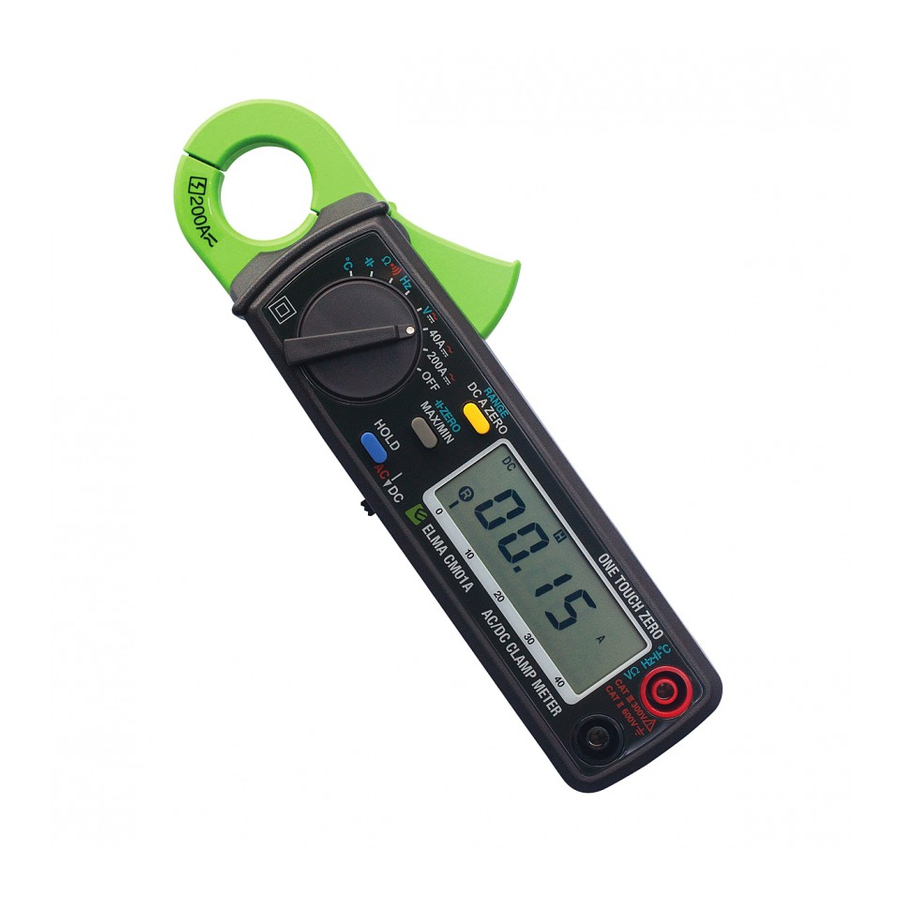
Elma CM-01A 2. Instrument beskrivelse 1. Tang kæber/Tangkjeft 2. Kæbeåbner/Tangkjeft åpner 3. Drejeomskifter 4. Knap for valg af AC/DC 5. Data Hold knap Fastholder værdi på skærmen 6. MAX/MIN Hold Knap Fastholder minimum og maksimum værdi. Tryk én gang for at fastholde minimumsværdi og én gang mere for at fastholde maksimumværdi. - Page 6 Elma CM-01A 9. Lavt batteri symbol Når dette symbol vises er batterispædning for lav, og batteriet skal udskiftes (se Kap. 5). 10. Zero/Relativ symbol Når dette symbol vises er en referenceværdi valgt og fratrukket den viste værdi. Tryk på Zero knappen i 2 sekunder for at fjerne denne funktion. 11.
-
Page 7: Anvendelsesinstruktion
Elma CM-01A 3.Anvendelsesinstruktion 3.1. DC/AC strømmåling Advarsel: Prøveledninger skal frakobles instrumentets bøsninger før strømmåling udføres. 3.1.1 DC strøm a. Indstil drejeomskifteren på 40A eller 200A og vælg DC med AC/DC knappen. b. Tryk på Zero knappen for at nuljustere. c. Tryk på kæbe/kjeft åbneren og omslut den målte leder med kæberne/tangkjeften. -
Page 8: Dc/Ac Spændingsmåling
Elma CM-01A 3.2. DC/AC spændingsmåling Advarsel: Maksimalt input er 600V AC/DC. Overskridelse af dette kan medføre person- eller instrumentskade. 3.2.1. DC spændingsmåling a. Indstil drejeomskifteren på V DC. b. Tilslut prøveledningerne til instrumentets bøsninger. c. Tilslut prøvespidserne parallelt over det kredsløb som ønskes målt. d. -
Page 9: Kapacitansmåling
Elma CM-01A 3.3. Kapacitansmåling a. Indsæt adapteren i instrumentets bøsninger. b. Indsæt kapacitor i adaptoren. c. Hvis kapacitansen er mindre end 4nF, tryk Zero (capacitance) knap for at nulstille restkapacitet. d. Aflæs måleværdien i displayet. -
Page 10: Temperaturmåling
Elma CM-01A 3.4. Temperaturmåling a. Indsæt adapteren i instrumentbøsningerne. b. Indsæt en type-K termoføler i adapteren. c. Aflæs måleværdi i displayet. -
Page 11: Modstandsmåling
Elma CM-01A Advarsel: Før modstandsmåling foretages skal alle kredsløb frakobles spænding og eventuelle kapacitive ladninger skal aflades. 3.5 Modstandsmåling 3.5.1. Indstil drejeomskifteren til Ω. 3.5.2. Tilslut prøveledningerne i instrumentbøsningerne. 3.5.3. Tilslut prøvespidserne til modstanden eller kredsløbet som ønskes målt. 3.5.4. Aflæs måleværdi i displayet. 3.6. -
Page 12: Automatisk Og Manuel Skala
Elma CM-01A 3.11. Automatisk og manuel skala Tryk på Range knappen for manuelt at vælge skala. Hold knappen inde 2 sekunder for at returnere til automatisk skala. 3.12. Autosluk Instrumentet slukker automatisk hvis det ikke betjenes. Tryk og hold Hold knappen nede når instrumentet tændes for at frakoble denne funktion. - Page 13 Elma CM-01A Svensk manual 1.Egenskaper ......................15 2. Instrumentbeskrivning ..................16 3.Användarinstruktion ..................18 3.1. DC/AC strömmätning ................18 3.2. DC/AC spänningsmätning ..............19 3.3. Kapacitansmätning ................20 3.4. Temperaturmätning ................21 3.5 Resistansmätning .................. 22 3.6. Genomgångsmätning ................22 3.7.
- Page 14 Elma CM-01A KAT II 600V KAT III 300V Föroreningsgrad 2 SYMBOLER på instrument och i manualen: Risk. Se i manual Fara för elektrisk stöt. Dubbelisolerad Kan beröra spänningsförande delar. Jord AC (Växelström) DC (Likström) AC/DC (Växel- och likström) CE-märke Skall sorteras som elektronikavfall efter lokala bestämmelser.
-
Page 15: Egenskaper
Elma CM-01A Säkerhetsinformation- Läs innan användning Följ noggrannt all information för säker användning av instrumentet. ■ Använd aldrig instrumentet på spänningar över 600V. ■ Håll endast instrumentet i handtaget. ■ Använd inte ett skadat instrument. ■ Var försiktig vid arbete på spänningsförande anläggning. ■... -
Page 16: Instrumentbeskrivning
Elma CM-01A 2. Instrumentbeskrivning 1. Transformatortång 2. Tångöppnare 3. Vred 4. Knapp för val av AC/DC 5. Data Hold knapp Fryser värdet på skärmen 6. MAX/MIN Hold Knapp Fryser min- och max-värde. Tryck en gång för att frysa min-värdet och en gång till för att frysa max-värdet. - Page 17 Elma CM-01A 9. Lågt batteri symbol När denna symbol visas är batterispänningen för låg och batteriet skall bytas (se Kap. 5). 10. Zero/Relativ symbol När denna symbol visas är ett referensvärde valt och fråndraget det visade värdet. Tryck på Zero knappen i 2 sekunder för att gå ur denna funktion.
-
Page 18: Användarinstruktion
Elma CM-01A 3.Användarinstruktion 3.1. DC/AC strömmätning Varning: Testledningarna skall frånkopplas från instrumentets anslutningar innan strömmätning utförs. 3.1.1 DC ström a. Ställ vredet på 40A eller 200A och välj DC med AC/DC knappen. b. Tryck på Zero knappen för att nolljustera. c. -
Page 19: Dc/Ac Spänningsmätning
Elma CM-01A 3.2. DC/AC spänningsmätning Varning: Maximal input är 600V AC/DC. Överskridelse av detta kan medföra person- eller instrumentskada. 3.2.1. DC spänningsmätning a. Ställ vredet på V DC. b. Anslut testledningarna till instrumentets ingångar. c. Anslut testspetsarna parallellt över kretsen som skall mätas. d. -
Page 20: Kapacitansmätning
Elma CM-01A 3.3. Kapacitansmätning a. Sätt in adaptern i instrumentets ingångar b. Sätt i en kondensator i adaptern. c. Om kapacitansen är mindre än 4nF, tryck Zero (capacitance) knappen för att nollställa restkapacitans. d. Läs av mätvärdet i displayen. -
Page 21: Temperaturmätning
Elma CM-01A 3.4. Temperaturmätning d. Sätt in adaptern i instrumentets ingångar e. Sätt i en typ-K termogivare i adaptern f. Läs av mätvärdet i displayen. -
Page 22: Resistansmätning
Elma CM-01A Varning: Före resistansmätning utförs skall alla kretsar frånkopplas vad avser spänning och eventuella kapacitiva laddninger skall urladdas. 3.5 Resistansmätning 3.5.1. Ställ vredet på Ω. 3.5.2. Anslut testledningarna i instrumentingångarna. 3.5.3. Anslut testspetsarna till resistansen eller kretsen som skall mätas. 3.5.4. -
Page 23: Automatisk Och Manuell Skala
Elma CM-01A 3.11. Automatisk och manuell skala Tryck på Range knappen för att manuellt välja skala. Håll knappen inne 2 sekunder för att återgå till automatisk skala. 3.12. Autoavstängning Instrumentet slår automatiskt av om det inte används. Tryck och håll Hold knappen nere när instrumentet slås på... - Page 24 Elma CM-01A English user manual 1.Features ......................27 2. Panel Description ..................... 27 3.Operation Instructions ..................30 3.1. DC/AC Current Measurements ............30 3.2. DC/AC Voltage Measurements ............31 3.3. Capacitance Measurement ..............32 3.4. Temperature Measurement ..............33 3.5 Resistance Measurement ..............34 3.6.
-
Page 25: Pollution Degree
Elma CM-01A CAT II 600V CAT III 300V Pollution Degree 2 SYMBOLS showed on the clamp meter or in this manual: Caution, risk of danger. Refer to accompanying documents Caution, risk of electric shock. Double Insulation Application around and removal from HAZARDOUS LIVE conductors is permitted. - Page 26 Elma CM-01A Overvoltage Category I (CAT I): Equipment for connection to circuits in which measures are taken to limit the transient overvoltages to an appropriate low level. Overvoltage Category II (CAT II): Energy-consuming equipment to be supplied from the fixed installation.
-
Page 27: Features
Elma CM-01A 1.Features 1. 10 mA high resolution on 40A DC/AC range 2. Temperature (℃ or ℉) and Capacitance. 3. One touch zero for DCA adjustment. 4. Auto-range for V, A, Ω, F, and temperature. 5. 23 mm diameter jaw. 6. - Page 28 Elma CM-01A 2. Transformer Trigger This is used to open the jaw. 3. Function Selector Switch This is used to select the function user desired, such as DCA, ACA, DCV, ACV, Hz, Ohm and Continuity. 4. AC/DC Select Switch This is used to select AC or DC voltage or current. 5.
- Page 29 Elma CM-01A Once the max/min button is pressed, either MAX or MIN shall be displayed on LCD 14. Continuity Symbol If ohm and continuity function is selected, this symbol shall appear on LCD. 15. Units Symbols Once a function is selected, corresponding unit (V, Ω , A, or Hz) shall be displayed on LCD.
-
Page 30: Operation Instructions
Elma CM-01A 3.Operation Instructions 3.1. DC/AC Current Measurements WARNING: Make sure that all the test leads are disconnected from the meter's terminals for current measurement. 3.1.1 DC Current a. Set the rotary switch at 40A or 200A and move the sliding switch to b. -
Page 31: Dc/Ac Voltage Measurements
Elma CM-01A 3.2. DC/AC Voltage Measurements WARNING: Maximum input for DC V is 600, and for AC V is 600. Do not attempt to take any voltage measurement that exceeds the limits. Exceeding the limits could cause electric shock and damage to the clamp meter. -
Page 32: Capacitance Measurement
Elma CM-01A 3.3. Capacitance Measurement a. Plug the adapter into the terminal b. Insert the capacitor into the adapter. c. If the capacitance is less than 4nF, press ZERO (capacitance) button to zero the residual capacitance. d. Read the value from LCD. -
Page 33: Temperature Measurement
Elma CM-01A 3.4. Temperature Measurement g. Plug the adapter into the terminal h. Insert the K-type thermal couple into the adapter i. Read the temperature from LCD. WARNING: Before taking any in-circuit resistance measurement, remove power from the circuit being tested and discharge all the capacitors. -
Page 34: Resistance Measurement
Elma CM-01A 3.5 Resistance Measurement 3.5.1. Set the rotary switch at Ω. 3.5.2. Insert the test leads into the input jack. 3.5.3. Connect the test prods of the test leads to the two ends of the resistor or circuit to be measured. 3.5.4. -
Page 35: Finding The Max/Min Value
Elma CM-01A 3.10. Finding the MAX/MIN Value Press the MAX/MIN button to enable the maximum and minimum values to be recorded and updated during measurement. Push the button once, the maximum value shall be displayed and updated. Push again (second push), the minimum value shall be displayed. -
Page 36: Specifications
Elma CM-01A 4.Specifications(23° ° ° ° C ± 5° ° ° ° C ) DC Current: Range Resolution Accuracy Overload Protection 40 A 10mA ±1.5%±2dgts DC 400A 0-150 A 100mA ±1.5%±2dgts DC 400A 150-200 A 100mA ±2.2%±2dgts DC 400A AC Current: Range Resolution Accuracy... - Page 37 Elma CM-01A Resistance (Ω):(open voltage 0.4V) Range Resolution Accuracy Overload Protection 400Ω 0.1Ω ±1.5%±2dgts AC 600V 4KΩ 1Ω ±1.5%±2dgts AC 600V 40KΩ 10Ω ±1.5%±2dgts AC 600V 400KΩ 100Ω ±1.5%±2dgts AC 600V 4MΩ 1KΩ ±1.5%±2dgts AC 600V 40MΩ 10KΩ ±1.5%±2dgts AC 600V Frequency: (Auto, sensitivity selected by pressing RANGE Button, Sine Wave) Range...
- Page 38 Elma CM-01A Conductor Size: 23mm max. (approx.) Battery Type: two 1.5V SUM-3 Display: 3 3/4 LCD with 40 seg. Bargraph Range Selection: manual Overload Indication: left most digit blinks Power Consumption: 10 mA (approx.) Low battery Indication: Sampling Time: 2 times/sec.(display) / 20 times/sec. (bargraph) Auto-Power-Off: 30 minutes Operating Temperature:-10 °...
-
Page 39: Battery Replacement
Elma CM-01A 5.Battery Replacement When the low battery symbol is displayed on the LCD or LCD display is dark, replace the old batteries with two new batteries. 5.1. Turn the power off and remove the test leads from the clamp meter. - Page 40 Elma CM-01A md19/4-13...
Need help?
Do you have a question about the CM01A and is the answer not in the manual?
Questions and answers