Table of Contents
Advertisement
Quick Links
Advertisement
Table of Contents

Related Manuals for Elma Instruments iTest 7400


Summary of Contents for Elma Instruments iTest 7400
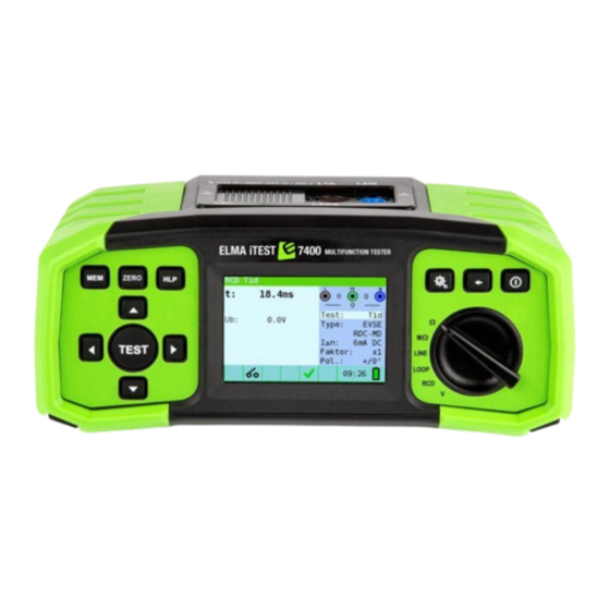
- Page 1 Manual Elma iTest 7400 Multifunction tester ENGLISH EAN: 5706445140428...
-
Page 2: Table Of Contents
Elma iTest 7400 Multifunction tester Preface ............................... 4 Safety instructions ............................5 Warnings and notes ..........................5 Batteries ............................. 7 Charging ............................7 Precautions on charging of new battery cells or cells unused for a longer period ........7 Standards applied ..........................8 Instrument description .......................... -
Page 3: Change Log
Elma iTest 7400 Multifunction tester Service ............................. 38 Batteries ............................38 Technical specifications ..........................39 Insulation resistance ........................39 Continuity resistance ........................40 RCD testing ............................40 Fault loop impedance and prospective fault current................42 Line impedance and prospective short-circuit current ............... 43 Voltage, frequency, and phase rotation .................... -
Page 4: Preface
• Instrument screenshots shown in this document may differ slightly from the actual instrument displays due to firmware updates or modifications. • Elma Instruments reserves the right to implement technical changes without prior notice as part of ongoing product development. -
Page 5: Safety Instructions
To ensure maximum operator safety during tests and measurements, it is strongly advised to keep your Elma iTest 7400 in optimal condition and free from damage. Please take into account the following general warnings while using the instrument. -
Page 6: Notes Related To Measurement Functions
Elma iTest 7400 Multifunction tester 2.1.3.2 Insulation resistance • Insulation resistance measurement should only be performed on de-energized objects! • Ensure all loads are disconnected and all switches are closed when measuring insulation resistance between installation conductors. • Avoid contact with the test object during measurement or before it is fully discharged to prevent the risk of electric shock. -
Page 7: Batteries
Elma iTest 7400 Multifunction tester 2.1.4.6 Line impedance • Isc depends on Z, Un and scaling factor • The current limit depends on fuse type, fuse current rating, fuse trip-out time • The specified accuracy of tested parameters is valid only if the mains voltage is stable during the measurement. -
Page 8: Standards Applied
Elma iTest 7400 Multifunction tester 2.5 Standards applied The Elma iTest 7400 is manufactured and tested in accordance with the following regulations: Electromagnetic compatibility (EMC) Electrical equipment for measurement, control and laboratory use – EMC requirements EN 61326 Class B (Hand-held equipment used in controlled EM environments) -
Page 9: Instrument Description
Elma iTest 7400 Multifunction tester 3 Instrument description 3.1 Front panel Legend: 1. ON/OFF key, to switch the instrument on and off. The instrument will automatically switch off (APO) after the last key press and no voltage is applied. 2. Function selector switch 3. -
Page 10: Back Panel
Elma iTest 7400 Multifunction tester 3.3 Back panel Legend: 1. Battery/fuse compartment cover 2. Information label 3. Fixing screws for battery/fuse compartment cover ② ① ③ Figure 3-3 Back panel Legend: 1. Fuse F1 2. Fuse F2 3. Fuse F3 4. -
Page 11: Bottom View - Information Label
Elma iTest 7400 Multifunction tester 3.4 Bottom view – Information label Figure 3-5 Bottom panel information label 3.5 Carrying the instrument The neck strap supplied allows the instrument to be carried in a variety of different ways. The operator can choose the most appropriate method based on the tasks they are performing. -
Page 12: Instrument Operation
Elma iTest 7400 Multifunction tester 4 Instrument operation 4.1 Symbols and messages on the instrument display The instrument display is divided into several sections. Legend: 1. Function line 2. Result field: In this field the main result and sub-results are displayed. -
Page 13: Status Symbols
Elma iTest 7400 Multifunction tester 4.3 Status symbols Dangerous voltage Test leads are compensated (optional) Measurement cannot be started Dangerous voltage on PE Result is not ok Result is ok RCD open or tripped RCD closed Measurement can be started... -
Page 14: Performing Tests
Elma iTest 7400 Multifunction tester 4.5.3 Performing tests When symbol is displayed test can be started by pressing the TEST button. After completion of the test its result value and status will be displayed. In case of a PASSED measurement, result value will be displayed in black color along with the status symbol. -
Page 15: Help Screen
Elma iTest 7400 Multifunction tester 4.7 Help screen The Help screens contain diagrams that show the correct use of the device. • Press the HELP key to enter the help screen. • Press the HELP key or the ESC key to exit the help screen. -
Page 16: Continuity Measurement
Elma iTest 7400 Multifunction tester 3. Ensure that no voltages are present on the object to be tested. 4. Connect test leads. 5. Check status fields for warnings. is displayed, test can be performed. 6. Press TEST to start test. - Page 17 Elma iTest 7400 Multifunction tester 1. Select the Ω, continuity function, with the function selector switch, and select LowΩ mode with the navigation keys. 2. Set test parameters: Select Limit to set high limit resistance value. 3. Connect test leads to the instrument.
-
Page 18: Continuity Test
Elma iTest 7400 Multifunction tester 5.2.2 Continuity test Continuous low-value resistance measurements can be performed without pole reversal of the test voltages and a lower test current (a few mA). In general, the function serves as an ordinary ohmmeter with low-test current. -
Page 19: Testing Rcds
For trip-out time measurement selected nominal differential current can be multiplied by ½, 1, 2 or 5. 5.3.4 RCD type and test current starting polarity Elma iTest 7400 enables testing of general (non-delayed) and selective (time-delayed) RCDs. The types of RCD the instrument is suitable for testing include: •... -
Page 20: Testing Selective (Time-Delayed) Rcds
Elma iTest 7400 Multifunction tester Test current starting polarity can be started with the positive half-wave at 0° or with the negative half-wave at 180°. Figure 5-11 Test current started with positive or negative half-wave 5.3.5 Testing selective (time-delayed) RCDs Selective RCDs demonstrate delayed response characteristics. - Page 21 Elma iTest 7400 Multifunction tester 5.3.7.1 Contact voltage measurement Notes: • Parameters set in this function are also kept for all other RCD functions! • The measurement of contact voltage does not normally trip an RCD. However, the trip limit may be exceeded as a result of leakage currents flowing through the PE conductor or a capacitive connection between the L and PE conductor.
- Page 22 Elma iTest 7400 Multifunction tester 5.3.8 RCD trip-out time, RCD t Trip-out time measurement is used to verify the effectiveness of an RCD. This is achieved by a test simulating an appropriate fault condition. Trip-out times vary between standards and are listed below.
- Page 23 Elma iTest 7400 Multifunction tester 6. After the test is done, measured results are displayed. Test result is ok, Test result is not ok, Trip-out time, Uc: Contact voltage. Figure 5-16 Example of trip-out time measurement results 5.3.9 RCD trip-out current, RCD I This test is used to determine the minimum current required to trip the RCD.
- Page 24 Elma iTest 7400 Multifunction tester 6. After the test is done, measured results are displayed. Test result is ok, Test result is not ok, Trip-out current, Uci: Contact voltage, Trip-out time. Figure 5-18 Example of trip-out current measurement result 5.3.10...
-
Page 25: Fault Loop Impedance And Prospective Fault Current
Elma iTest 7400 Multifunction tester 7. After the test is done, measured results are displayed. Test result is ok, Test result is not ok, x1 (+): Trip-out time (1×IΔn, 0°), x1 (-): Trip-out time (1×IΔn, 180°), x5 (+): Trip-out time (5×IΔn, 0°), x5 (-): Trip-out time (5×IΔn, 180°),... - Page 26 Elma iTest 7400 Multifunction tester 5.4.1.1 Loop impedance measurement 1. Select the LOOP function, with the function selector switch, and select Loop mode with the navigation keys. 2. Set test parameters: Select Type to set fuse/MCB type. Select Time to set disconnection time limit.
- Page 27 Elma iTest 7400 Multifunction tester 5.4.2 Loop impedance RCD The fault loop impedance is measured with a low test current to avoid tripping the RCD. This function can also be used for fault loop impedance measurement in systems equipped with RCDs which have a rated trip-out current of 30 mA and above.
- Page 28 Elma iTest 7400 Multifunction tester 5.4.3 Loop impedance Rs (for adjustable current) The fault loop impedance is measured with a low test current to avoid tripping the RCD. It is possible to adjust the value of the RCD, while the test current depends on the chosen value. With this function it is possible to test each RCD-type with the maximum possible current without tripping the RCD.
-
Page 29: Line Impedance And Prospective Short-Circuit Current
Elma iTest 7400 Multifunction tester 5.5 Line impedance and prospective short-circuit current 5.5.1 Line impedance The line impedance is a measurement of the impedance of the current loop when a short-circuit to the neutral conductor occurs (conductive connection between phase conductor and neutral conductor in single-phase system or between two phase conductors in three- phase system). -
Page 30: Voltage Drop
Elma iTest 7400 Multifunction tester 6. After the test is done, measured results are displayed. Test result is ok, Test result is not ok, Fault loop impedance, Isc: Prospective short-circuit current, Lim: Calculated fault current limit. Figure 5-30 Example of line impedance measurement results 5.5.2 Voltage drop... -
Page 31: Voltage And Phase Rotation
Elma iTest 7400 Multifunction tester 8. Check status fields for warnings. is displayed, test can be performed. 9. After the test is done, measured results are displayed. Test result is ok, Test result is not ok, ΔU: Voltage drop at the test point... - Page 32 Elma iTest 7400 Multifunction tester 4. The voltage and frequency test operates continuously, capturing and displaying fluctuations in real-time during the measurement. U L-N: Voltage between phase and neutral conductors, U L-PE: Voltage between phase and protective conductors, U N-PE: Voltage between neutral and protective conductors.
-
Page 33: Storing Measurements
Elma iTest 7400 Multifunction tester 6 Storing measurements After the measurement is completed, results can be stored in the internal memory of the instrument together with the sub-results and function parameters. 6.1 Overview • The instrument can store up to 1000 measurements •... - Page 34 Elma iTest 7400 Multifunction tester • Press MEM to enter memory storage menu. Record: Next record number in red letters, Date: Measurement date (dd/mm/yyyy), Time: Measurement time (hh:mm:ss) O_ID: Object ID number L_ID: Location ID number C_ID: Customer ID number...
-
Page 35: Recalling Saved Results
Elma iTest 7400 Multifunction tester 6.3 Recalling saved results 1. Press MEM to enter memory menu. See Figure 6-3 Memory storage menu. Last saved record will be shown. 2. Use ▲▼ navigation keys to step through records. Existing records’ IDs can be changed by pressing the ◀... -
Page 36: Data Transfer
Elma iTest 7400 Multifunction tester 7 Data transfer Stored results can be transferred to a PC for tasks such as creating simple reports or performing further analysis in Excel. The instruments connects to the PC using USB communication. 7.1 MFT Records - PC software Transferring stored records from the instrument to a PC is managed through the MFT Records application. - Page 37 Elma iTest 7400 Multifunction tester 7. Click Excel to export all records to Excel file. Default location for saving.xlsx files is Documents/MFT/. Figure 7-5 Export records to Excel file Figure 7-6 Example of generated Excel file...
-
Page 38: Maintenance
For repairs under warranty, or at any other time, please contact your distributor. Unauthorized persons are not allowed to open the Elma iTest 7400. There are no user-replaceable components inside the instrument, except for the three fuses inside the battery compartment, refer to chapter 8.18.1. -
Page 39: Technical Specifications
Elma iTest 7400 Multifunction tester 9 Technical specifications 9.1 Insulation resistance Insulation resistance (nominal voltage 50 VDC) Measurement range according to 61557 is 50 kΩ - 80 MΩ. Measuring range (MΩ) Resolution (MΩ) Accuracy 0.100 - 1.999 0.001 ± (5 % of reading + 3 digits) 2.00 - 80.00... -
Page 40: Continuity Resistance
Elma iTest 7400 Multifunction tester 9.2 Continuity resistance 9.2.1 R Low Measuring range according to EN61557-4 is 0.1 Ω - 1999 Ω. Measuring range (Ω) Resolution (Ω) Accuracy 0.10 - 19.99 0.01 ± (3 % of reading + 3 digits) 20.0 - 99.9... -
Page 41: Contact Voltage
Elma iTest 7400 Multifunction tester EVSE RCD test current selection according to IEC 62955: IΔn (mA) ½ × IΔn 1 × IΔn 2 × IΔn 5 × IΔn 10 × IΔn 33 × IΔn RCD IΔ ✓ IΔn (mA) ½ × IΔn 1 ×... -
Page 42: Fault Loop Impedance And Prospective Fault Current
Elma iTest 7400 Multifunction tester Measuring range (V) Resolution (V) Accuracy 3.0 - 9.9 (-0%/+10%) of reading + 5 digits 10.0 - 99.9 9.4 Fault loop impedance and prospective fault current 9.4.1 Loop impedance Loop impedance Measuring range according to EN61557-3 is 0.25 Ω - 1999 Ω. -
Page 43: Line Impedance And Prospective Short-Circuit Current
Elma iTest 7400 Multifunction tester 9.5 Line impedance and prospective short-circuit current Line impedance Measuring range according to EN61557-3 is 0.25 Ω – 1999 Ω. Measuring range (Ω) Resolution (Ω) Accuracy 0.20 - 19.99 0.01 20.0 - 99.9 ± (5 % of reading + 5 digits) -
Page 44: General Data
Elma iTest 7400 Multifunction tester 9.7 General data Power supply voltage 9 V DC (6 × 1.5 V battery cells, size AA) Power supply adapter 12 V DC / 1000 mA Battery charging current < 600 mA (internally regulated) Voltage of charged batteries 9 V DC (6 ×...
Need help?
Do you have a question about the iTest 7400 and is the answer not in the manual?
Questions and answers