Table of Contents
Advertisement
Available languages
Available languages
Quick Links
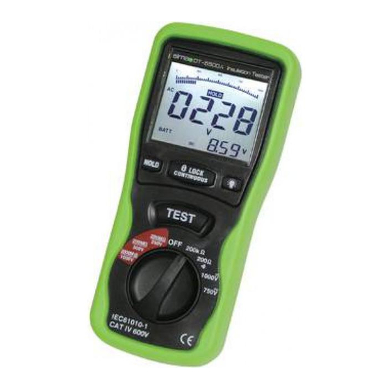
Elma DT5500A
Dansk/norsk vejledning Side 4 - 11
Svensk manual
English usermanual
El-Nummer: 63 98 206 581
EAN-Nummer: 5706445840021
Sida 12 - 19
Page 20 - 27
Advertisement
Table of Contents

Subscribe to Our Youtube Channel
Related Manuals for Elma Instruments DT5500A


Summary of Contents for Elma Instruments DT5500A
- Page 1 Elma DT5500A Dansk/norsk vejledning Side 4 - 11 Svensk manual Sida 12 - 19 English usermanual Page 20 - 27 El-Nummer: 63 98 206 581 EAN-Nummer: 5706445840021...
-
Page 2: Table Of Contents
Dansk/norsk vejledning ......................4 Sikkerhedsinformation ......................4 Sikkerhedssymboler......................5 Ved servicering ........................5 Specifikationer ........................5 Generelle specifikationer ..................... 5 Miljømæssige tilstande ......................5 Vedligeholdelse og rengøring ....................5 Diverse specifikationer ......................5 Elektriske specifikationer ..................... 6 Dele og funktioner ........................ 7 Batteri tjek og udskiftning af dette .................. - Page 3 Elverktyg och små enheter ....................18 Motorer ..........................18 Kablar ..........................19 English Manual ........................20 Safety information ......................20 Safety symbols: ......................... 21 Specifications ........................21 General Information ......................21 Environment conditions:..................... 21 Maintenance & Clearing: ....................21 Other specifications: ......................21 Electrical Specifications .....................
-
Page 4: Dansk/Norsk Vejledning
Elma DT5500A side 4 Dansk/norsk vejledning Digital isolationstester – Elma DT5500A Insulation Tester TEST 200M 200k 250V 200M 500V 1000V 1000V 750V IEC61010-1 CAT IV 600V Sikkerhedsinformation Før man bruger eller servicerer på instrumentet skal følgende sikkerhedsinformation læses grundigt igennem. -
Page 5: Sikkerhedssymboler
Elma DT5500A side 5 Sikkerhedssymboler Fare, referer til betjeningsvejledningen før brug Farlig spænding Instrumentet er dobbelt isoleret eller beskyttet med forstærket isolation Ved servicering Brug kun specificerede reservedele iht. EN 61010-1 Specifikationer Generelle specifikationer Miljømæssige tilstande Installations kategori III, 1000V iht. IEC1010 ... -
Page 6: Elektriske Specifikationer
Elma DT5500A side 6 Lav batteri indikering: Hvis batterispændingen er ved at være lav, vil følgende symbol blive vist i displayet. Operationstemperatur: 0C til 40C (32F til 104F) og fugtighed under 80% Opbevaringstemperatur: -10C til 60C (14F til 140F) og fugtighed under Strømforsyning:... -
Page 7: Dele Og Funktioner
Elma DT5500A side 7 Meg OHM: Terminal spænding Område Opløsning Nøjagtighed Teststrøm Kortslutningsstrøm 0,125Ω – 4,000M 0,001MΩ 125V (0% - +10%) + (2%+10) 1mA@load 125k < 1mA 4,001 – 40,00M 0,01M + (2%+10) 40,01 – 400,0M 0,1M + (4%+5) 400,1 – 4000M... -
Page 8: Batteri Tjek Og Udskiftning Af Dette
Elma DT5500A side 8 Batteri tjek og udskiftning af dette a) Hvis batterispændingen ikke er tilstrækkelig vil displayet vise symbolet. Der kræves udskiftning af 6 stk. nye batterier, type 1,5V, str. AA. b) Åbn batteridækslet ved at løsne de 4 skruer på bagsiden. -
Page 9: B) Display Indikering
Elma DT5500A side 9 b) Display indikering Hoveddisplay (øverste display): Indikerer nuværende testværdier Underdisplay (nederste display): Indikerer output DCV, mens man tester isolationsmodstanden, og batterispændingen ved ACV. Analoge markør: Indikerer nuværende testværdi - i synkron med hoveddisplayet. Hvis dette symbol vises når isolationsmodstanden testes, og samtidigt blinker - er det fordi, at spændingen er over 30V. -
Page 10: Lavmodstands (Gennemgangs) Måling
Elma DT5500A side 10 d) Ved at man slipper ”TEST” knappen eller trykker denne ned i ”LOCK” status, kan man returnere fra denne status til normal status og derved frakoble isolationsspændingen. Samtidigt med dette vil de viste værdier på hoveddisplayet blive holdt og underdisplayet viser stadigvæk, ved hvilket spændingsniveau der... -
Page 11: Motorer
Elma DT5500A side 11 Motorer Ved AC: Afbryd motoren fra kredsen ved at demontere ledningerne på motorklemmerne eller ved at åbne hovedafbryderen. Hvis motoren også har en starter, må starteren blive holdt, på en eller anden måde, i ”Tænd” positionen. I denne situation, vil den målte modstand inkludere modstanden for motoren, ledningen og andre komponenter monteret imellem motor og hovedafbryder. -
Page 12: Svensk Manual
Elma DT5500A side 12 Svensk Manual Digital isolationstestare – Elma DT5500A Insulation Tester TEST 200M 200k 250V 200M 500V 1000V 1000V 750V IEC61010-1 CAT IV 600V Säkerhetsinformation Läs följande säkerhetsinformation noggrannt innan du använder eller utför service på instrumentet. -
Page 13: Säkerhetssymboler
Elma DT5500A side 13 Säkerhetssymboler Fara, refererar till manualen för anvisningar. Farlig spänning Instrumentet är dubbelisolerat eller skyddat med förstärkt isolering Vid service Använd endast specificerade reservdelar enligt EN 61010-1 Specifikationer Allmänna specifikationer Miljö Installationskategori III, 1000V enligt IEC1010 ... -
Page 14: Elektriska Specifikationer
Elma DT5500A side 14 Indikering låg batterinivå: Om batterispänningen börjar närma sig noll, visas följande symbol i displayen. Arbetstemperatur: 0C till 40C (32F till 104F) och fuktighet under 80 % RH Förvaringstemperatur: -10C till 60C (14F till 140F) och fuktighet under Stömförsörjning:... -
Page 15: Delar Och Funktioner
Elma DT5500A side 15 Mega OHM: Terminal Spänning Område Upplösning Noggrannhet Testström Kortslutningsström 0,125Ω – 4,000M 0,001MΩ 125V (0% - +10%) + (2%+10) 1mA@last 125k < 1mA 4,001 – 40,00M 0,01M + (2%+10) 40,01 – 400,0M 0,1M + (4%+5) 400,1 – 4000M... -
Page 16: Batteribyte
Elma DT5500A side 16 Batteribyte Hur man ansluter testledningarna På M området och 400/Bz, AC V, DC V: Koppla den röda testledningen till V anslutningen och den svarta ledningen till COM anslutningen Batteri - kontroll och byte a) Om batterispänningen inte är tillräcklig visar displayen . -
Page 17: B) Display Indikering
Elma DT5500A side 17 b) Display-indikering Den primära displayen (Övre displayen): Indikerar nuvarande mätvärden Den sekundera displayen (nedre displayen): Indikerar DC V, medan man mäter isolation och batterispänningen vid AC V. Analog markör: Indikerar den nuvarande mätvärdet, synkroniserat med den primära displayen. -
Page 18: Lågmotstånds- (Genomgångs-) Mätning
Elma DT5500A side 18 På den undre displayen visas isolationsspänningen (t.ex. 500V DC). Pilsymbolen blinker och ett larm piper. d) Genom att släppa ”TEST” knappen eller låsa denna i ”LOCK” läge, kan man återgå från denna status till normal och därigenom koppla från matningsspänningen. -
Page 19: Kablar
Elma DT5500A side 19 Vid DC: Koppla bort motorn från kretsen. För att testa borsthållare, rotor och stator, förbind instrumentets ena testledning till jordklämman på motorn och den andra till bortshållaren på kommutatorn. Om man får ett dåligt värde måste borstarna lyftas bort och rotorn, statorn och borsthållaren testas individuellt. -
Page 20: English Manual
Elma DT5500A side 20 English Manual Digital insolation tester instruction manual Insulation Tester TEST 200M 200k 250V 200M 500V 1000V 1000V 750V IEC61010-1 CAT IV 600V Safety information Read the following safety information carefully before attempting to operate or service the meter. -
Page 21: Safety Symbols
Elma DT5500A side 21 Safety symbols: Caution refer to this manual before using the meter. Dangerous voltages. Meter is protected throughout by double insulation or reinforced insulation. When servicing, use only specified replacement parts. CE Comply with EN-61010-1 Specifications General Information Environment conditions: ①... -
Page 22: Electrical Specifications
Elma DT5500A side 22 Storage Temperature: -10ºC to 60ºC (14ºF to 140ºF) and Humidity below 70% RH DC9V (6x1.5V Size “AA” battery or Equivalent) Power source: Dimensions: 200(L) x 92(W) x 50(H) mm Weight: Approx 700g include battery Accessories: Test leads, 6pcs battery, Carrying case, manual. -
Page 23: Meg Ohms
Elma DT5500A side 23 Meg OHMS Test Short Terminal Voltage Range Resoluti Accuracy Current circuit current Ω Ω ≤ 125V(0%~+10%) 0.125~4.000 M 0.001M +(2%+10) Ω Ω @load 4.001~40.00 M 0.01M +(2%+10) Ω Ω 125kΩ 40.01~400.0 M 0.1M +(4%+5) Ω Ω... -
Page 24: How To Connect Test Leads
Elma DT5500A side 24 How to connect test leads. On MΩ Range , and 400Ω/BZ ACV,.DCV, Connect the red test lead into the “VΩ” terminal and the black lead into the “COM” terminal. Battery Check-UP & Replacement a)As battery power is not sufficient. LCD will display . -
Page 25: Display Indicators
Elma DT5500A side 25 Display Indicators The Primary Display:Indicate the current function testing values The Secondary Display: It shows the output DCV while you test the insulation resistance, and the battery voltage while the ACV The Analog Bar:indicate the current function testing value in synchronous with the primary display. -
Page 26: Low Resistance (Continuity) Measurements
Elma DT5500A side 26 d)Being free from the “TEST” button or pushing down the “TEST” button in the “LOCK “ status can exit from the “LOCK” status and shutoff the high-voltage,synchronously, the resistance values is indicated in the primary display will be held, and the secondary display still be in the status of monitoring the insulation voltage for the tested. - Page 27 Elma DT5500A side 27 other lead to One of the motor leads. DC-Disconnect the motor from the line. To test the brush rigging,field coils and armature connect one megohmmeter lead to the grounded motor housing and the other lead to the brush on the commutator. If the resistance...
-
Page 28: Cables
Elma DT5500A side 28 Cables Disconnect the cable from the line. Also disconnect opposite end to avoid errors due to leakage from other equipment. Check each conductor to ground and /or lead sheath by connecting one megohmmeter lead to a ground and /or lead sheather and the other megohmmeter lead to each of the conductors in turn.
Need help?
Do you have a question about the DT5500A and is the answer not in the manual?
Questions and answers
Har et DT 5500 instrument. Hvorfor blir måleresultatet 1 Mohm når jeg kortsluttet målepinnene?
The Elma Instruments DT5500A shows a measurement result of 1 MΩ when the test leads are shorted because of its internal design and measurement characteristics. Some insulation testers display a default resistance value when no significant resistance is detected, instead of showing zero. This can be due to internal leakage resistance, auto-ranging behavior, or an internal safeguard to indicate that the device is operational. The device may also have a minimum display threshold that prevents it from showing absolute zero resistance.
This answer is automatically generated