
Related Manuals for Digital Dream DM500


Summary of Contents for Digital Dream DM500
- Page 1 The version of 20170806 Handheld Motion Controller For Engraving Machine DM500 User’s Manual...
- Page 2 1 DM500 Motion Controller Introduction 1.1 Introduction of Product Digital Dream has a 20 years history in the numerical control industry, specializing in the research, devel- opment and production of various CNC (Computer Numerical Control) systems. DigitalDream aims to combine high quality and high reliability with affordability.
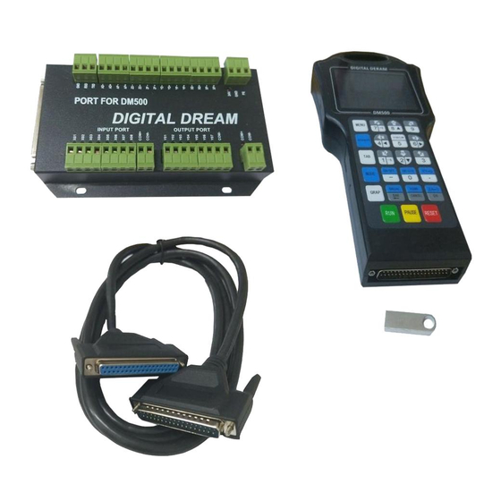
- Page 3 1.3 Appearance, Structure and Size of Product The DM500 motion controller contains the handheld motion controller,circuit switching wiring board,and HDMI digital high-definition transmission cable. The handheld motion controller and wiring board are communicated by 2 Meter 37 pins HDMI digital high-definition transmission cable which is shielding twisted-pair cable to avoid interference.
- Page 4 The front panel consists of 23 user keys and the 3.5’’ (480*320 ) LCD. 3.5'' Screen 23 user’s keys 37 pins Male Interface 37 pins Female Interface Page -3 DM500 User’s Manual...
- Page 5 1.4 Explanation of Abbreviations When operating the DM500 Controller, the users will come across some English abbreviations. Here a list with explanations FRO: Feed Rate Override SRO: Spindle Rate Override SRJ: Jog Speed Setting F: Feed rate, unit is mm/min S: Spindle Speed, unit rev/min.
- Page 6 2 Wiring Wiring Board Drawing Page -5...
- Page 7 2.1 The Wiring Board Interface Port Board for DM500 Power supply For Inputs and Outputs DC24V COM+ RS232 communication 5.1K port X Axis Home Y Axis Home 5.1K Z Axis Home A Axis Home Probe Extended Input Port 1 (E-stop)
- Page 8 Spindle Speed Setting 3 Output Port Y02/Y03/Y03 are for settings of spindle 8 different speeds. Open-collector output,installed,Current:500mA,Voltage:30V Alarm Output Cooling output Port (M8/M9) Lubrication output Port (M10/M11) Receive Port of communication Send Port of Communication RS232 Ground of Communication Port Page -7 DM500 User’s Manual...
- Page 9 DB37 Filter Filter Switch Power Switch Power Suply 2 Supply 1 +24V +24V COM- COM+ Main controller use the same power supply with Input/output ports.(no recommended). DB37 Filter Switch Power Supply +24V COM- COM+ Page -8 DM500 User’s Manual...
- Page 10 When the Inputs and Output Ports (COM+ COM-) share the same Power supply with the controller: Motion Controller COM+ COM- Motion Controller COM+ Proximity Switch Normal Open Mode COM- It’s the best to use the first independent power supply method.Logic low Effective.NPN normal open proximity switch. Page -9 DM500 User’s Manual...
- Page 11 COM- There is 7 output pins,the electric circuit just as the above file showing. When you connect the relay,pls install a fly-wheel diode as the drawing showing. The first Independent power supply method is recommended. Page -10 DM500 User’s Manual...
- Page 12 Pls use twist Shielding Twist cable for the connection Shielding Cable Y,Z,A axis wiring are same as X axis; The controller use differencial output methods,And The Max. Output Frequency is 500Khz; Cannot connect as Common anode and cathode; Page -11 DM500 User’s Manual...
- Page 13 3. Definition of keys The Panel Keys showed as the photo below: Page -12 DM500 User’s Manual...
- Page 14 3: Parameter value decreases 1: Negative movement of Y Axis; Reset and E-STOP. 2: Data 2 input; Shift between Reset and Ready 3: Cursor moves down. 1: Negative movements for A Axis; 2: Data 3 Input. Page -13 DM500 User’s Manual...
- Page 15 3: Current machining file.(if the files name in red background color,means the controller cannot read the U-disk) 4: Total working time 5: Current operation Rights 6: The information page 7: Main Page 8: File Page 9: Parameter Page Menu tree structure Menu Main page File page Para page Page -14 DM500 User’s Manual...
- Page 16 X Find Mach Zero Admin Password Setting Y Find Mach Zero Super Admin Password Setting Z Find Mach Zero Probe Software Registration Start Line Lifetime Setting Unlock Break Lifetime Setting Nearest Point Mul Origin Save origin Load Origin Page -15 DM500 User’s Manual...
- Page 17 6. Current workpiece Coordination: G54/G55/G56/G57/G58/G59 workpiece coordination;Mach Coordi- nation; 7. Manually High/low speed; 8. Output signal status; 9. Input signal status; 10. Version information and Programming date; 11. Machining information: G code information when automatically machining;Errors. Page -16 DM500 User’s Manual...
- Page 18 The Name of folders and files, the size of files and the time and date of manipulation. The blue strip indicates the current valid target location. Page -17 DM500 User’s Manual...
- Page 19 G code and go back to the Main Page for processing the G-code file. 4.4.2 The Operation of the File Page When at the File Page,and Press the key and the page pop up the list as below: Page -18 DM500 User’s Manual...
- Page 20 Index No. Press to select the parameter and start to write it.Press the data keys and press to save the values;if press the key then cancelled saving. Page -19 DM500 User’s Manual...
- Page 21 4.5.2 The Operation of the Parameter Page When at the Parameter Page,and Press the key and the page pop up the list as above. About the File management,we will describe it in next chapter. Page -20 DM500 User’s Manual...
- Page 22 5. The Motion Controller DM500 Operation System status The Motion Controller will have some different status,now we explain the different status: 5.1.1 System Status: Reset Conditions: • when e-stop switch is triggered; • when reset key is pressed; • Error occured (Hard-limited switch or soft limited switches are triggered.) At the conditons,the system will shift the status to “Reset”,and stop running,to make sure the savety of the...
- Page 23 • The speed can be set at “SJR” or parameter adjustment. 5.2.3.2 Continuously High speed feeding Feeding to one direction at high speed. Condition: • Controller is in READY status; • Operate mode is CONT. Page -22 DM500 User’s Manual...
- Page 24 • Press the start key; • the controller will start to process the G-code file selected; • The controller status shift from “READY” to “BUSY” • When the work finished,the controller status back to “READY”. Page -23 DM500 User’s Manual...
- Page 25 The controller supplies G54-G59 6 kinds workpiece coordination and one MACH machine coordina- tion.Before running a G code file,the users need to decide one work piece coordinate. Conditions: • Controller is in READY status; • The screen go to “Main page”. Page -24 DM500 User’s Manual...
- Page 26 Save origin • Press the key and then ,then Press to confirm to save the Origin Position • Successively press the Key and then Mul Origin Load Origin ,then press to load the origin position. Page -25 DM500 User’s Manual...
- Page 27 9) If the user don’t change the origin positon of the work piece,and when the user changed different length cutters,just measure the thickness of the tool sensor and take the new data. 10) If the Z Axis Origin(Zero) position is changed,just repeat the action from 6-9. Page -26 DM500 User’s Manual...
- Page 28 4) Go to Parameter 69 and type in the thickness of the tool sensor.You should know it in advance. 5) Move the cutter above the tool sensor manually; 6) Press the key ,the press to probe. Probe Page -27 DM500 User’s Manual...
- Page 29 When there is Power-cutoff,Reset,E-stop,Limted-switch alarm and U-disk disconnected happened,that will produce a breakpoints.But,our system can automatically record the breakpoints and continue to process from the breakpoint. Conditions: • Controller is in READY status; • The screen go to “Main page” Page -28 DM500 User’s Manual...
- Page 30 FRO controls the the machine real time Feed Speed.Use A+ and Z- to adjust the Feed Speed in 10% increments.The relationship betwen the real time feed speed and the F value is: Real time feed speed=F(Feeding Value) x FRO Conditions: • Controller is in READY status; • The screen go to “Main page” Page -29 DM500 User’s Manual...
- Page 31 • As we used 3 output pins to define 8 spindle speeds.Here the S Value is from 1-8.For example if the Max spindle speed is 24000RPM,and the S value is 3,then the spindle speed is 24000*3/8=9000RPM. Press the key or change the value of S. Press the Key to Start or Stop Spindle Page -30 DM500 User’s Manual...
- Page 32 Spindle Speed Pin 1 M701/M802 Y Home M501/M601 Spindle Speed Pin 2 M703/M803 Z Home M501/M601 Spindle Speed Pin 3 M704/M804 A Home M501/M601 Alarm Output M705/M805 Probe M501/M601 M506/M606 M706/M806 E-Stop M501/M601 M507/M607 M707/M807 Start/Probe M708/M808 Pause Page -31 DM500 User’s Manual...
- Page 33 Para# 423,Define the External input 1 or not: No For Example: M706: Wait for X06 input connection G60 G01 X100: Run to X100 position M806: Wait for X06 disconnection G90 G01 X200: Run to X200 position Page -32 DM500 User’s Manual...
- Page 34 • The updating file’s name should be INSTALL • At the subdirectory of the INSTALL file,there is no file which can named as “INSTALL” • After updating successfully,delete the INSTALl file from U-disk,or everytime restart the controller, it will update automatically. Page -33 DM500 User’s Manual...
- Page 35 • The Backup data should be save into the Setting file of the root directory of U-disk • Press ,type in the admin password,and enter Restore Para U Pls note the backup data should be saved into the “setting” file at the root directory of U-disk in Advance. Page -34 DM500 User’s Manual...
- Page 36 Please do the assignment in strict accordance with the assignment scope. e、Each parameter is set with default value in advance. Please use the setting value of default parameter under the situation of not understanding the actual function of this parameter. Page -35 DM500 User’s Manual...
- Page 37 Modification of the password Conditions: • Controller is in READY status; • The screen go to “Para page” Operation: • Press ,type in the old password and new password,click “YES”. Password Setting Pls note the window as below: DM500 User’s Manual Page -36...
- Page 38 1200 0~2000 mm/s acceleration, the stop accelera- tion can be set appropriately #265 stop Acceleration of Z in M_Ctrl mode 1200 0~2000 mm/s larger #266 stop Acceleration of A in M_Ctrl mode 0~2000 1200 degree/s Page -37 DM500 User’s Manual...
- Page 39 BOOL 0: Disable,1: Enable #429 Electric Level of E-stop On Box BOOL 1: High; 0:Low #446 Definition of the External Input 2 BOOL 2/1/0 0:Null,1:Start; 2:Probe Definition of the External Input 3 BOOL 0:Null,1: Pause Page -38 DM500 User’s Manual...
- Page 40 Y axis in fixed mode 0-9999 Mach(ine) coordinate system Height of Z axis before the XY move initial Z axis in fixed mode 0-9999 under the Mach(ine) coordinate system Back off distance after probing 0~200 Page -39 DM500 User’s Manual...
- Page 41 Time of the Logo Display 0.1-10 #495 circle of interpolation 0.002 0.002-0.01 circle of interpolation #250 enable of draw tool road BOOL 0:disable 1: enable #253 mode of draw BOOL 0:statue mode 1:line mode #495 Interpolation period 0.005 0.002~0.01 DM500 User’s Manual Page -40...
- Page 42 G19:Yp Zp Plane Selection Inch/Metric Shift Inch Input: G20; (G20、G21) Metric Input: G21 Reference Point G28 IP_; Middle Point Return To Reference Point Starting Point D_ ; Tool Radius compensation (G40~G42) D: Offset No. of Tool; G40: Cancel; Page -41 DM500 User’s Manual...
- Page 43 M507-M507(The detail see the Page 32) Y01-Y07 Output Open M601-M607(The detail see the Page 32) Y01-Y07 Output Close M701-M708(The detail see the Page 32) X01-X08 Input connection and delay M801-M809(The detail see the Page 32) X01-X08 Input disconnection and delay Page -42 DM500 User’s Manual...
Need help?
Do you have a question about the DM500 and is the answer not in the manual?
Questions and answers