
Related Manuals for Digital Dream DDCS-Expert


Summary of Contents for Digital Dream DDCS-Expert
- Page 1 D D C S - E x p e r t Standalone Motion Controller Users Manual V1 Shenzhen Digital Dream Numerical Technology Co., Ltd.
- Page 2 ● ● ● ● ● ● ● ● ● ● ● ● ● ● ● ● ● ● DDCS-Expert Brief technical feature ● ● ● ● ● ● ● ● ● ● ● ● ● ● ● ● ● ●...
- Page 3 ● ● ● ● ● ● ● ● ● ● ● ● ● ● ● ● ● ● ● ● ● ● ● ● ● ● ● ● ● ● ● Digital Dream Standalone Motion Controller Page-2 DDCS-Expert Users Manual...
- Page 4 The copyright of this manual belongs to Shenzhen Digital Dream Numerical Technology Co., Ltd. (herein after referred as Digital Dream Company). This manual and any image, table, data or other information contained in this manual may not be reproduced, transferred, or translated without any prior written permission of Digital Dream Company.
- Page 5 DDCS-Expert Brief technical feature: 1) Max. 5 Axis; 1M Hz output frequency for each axis; 2-4 Axis linear interpolation, any 2 axis circular interpolation; 2) 7 inch full color display screen; resolution ratio: 1024*600, 40 operation keys; 3) 24 photoelectric isolated digital inputs, 21 photoelectric isolated digital outputs;...
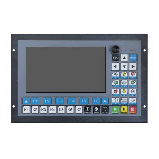
- Page 6 Appearance, Structure and Size of Product The DDCS-Expert is a small box that can fit in a window of a small control box or control cabinet. Four locking hooks fix this controller from the frame. The dimension you find in Figure 1-1 and Figure 1-2.
- Page 7 The front panel consists of 40 user keys and the 7 inch (1024*600) LCD. 7'' Screen 40 Buttons Figure 1-3 Front panel Figure 1-4 Back Side of the controller The only accessories is the USB extended cable. Figure 1-5 USB extended cable Digital Dream Standalone Motion Controller Page-6 DDCS-Expert Users Manual...
- Page 8 E-stop at once to avoid damage to humans, animals and the equipment. High voltage danger. The DDCS is connected to 24V DC. Obey and follow the electrici- ty safety rules of your country when connecting this equipment. Digital Dream Standalone Motion Controller Page-7 DDCS-Expert Users Manual...
- Page 9 Controller Panel and Operation Figure 2-1 DDCS-Expert (DDCSE) Controller Panel Keys Icon Definition Notes Return to previous menu In the software, press the key to return to previous menu. Go to Next Page In the software, press the key to the next page of the sub-menus.
- Page 10 1: High or Low Speed selection When the LED lights up, it is in high-speed mode. 2: Number “5”. 1: Breakpoint resume active When the LED lights up,t he breakpoint resume is active. 2: Number “0”. Digital Dream Standalone Motion Controller Page-9 DDCS-Expert Users Manual...
- Page 11 MPG status. Power on the DDCS-Expert controller, system popup the main page, and press F4 Key to go to the IO Port Page:...
- Page 12 Inverter Alarm input signal Customs alarm input signal 1 Customs alarm input signal 2 Customs alarm input signal 3 Customs alarm input signal 4 Customs alarm input signal 5 Tool close input signal (M304) Digital Dream Standalone Motion Controller Page-11 DDCS-Expert Users Manual...
- Page 13 In the controller default setting, we already define the Output port 21 as the “Spindle forward rotation control signal” . On the controller wiring board, we didn’ t name it as “Out21” , we name it as “FRO” . Figure 3-3 FOR Output Port Digital Dream Standalone Motion Controller Page-12 DDCS-Expert Users Manual...
- Page 14 IO block show as below: the X-axis zero signal is active,and IN01 Block is not on,because IN01 is not conductiong with COM-. Figure 3-5 The status is active but IN01 is not ON Digital Dream Standalone Motion Controller Page-13 DDCS-Expert Users Manual...
- Page 15 So now we finished the indroduction on the IO port.Only when the users understand how to set the IO port and how to inspect the IO page,it will help us on Wiring. Digital Dream Standalone Motion Controller Page-14 DDCS-Expert Users Manual...
- Page 16 Wiring Wiring Board Overview DDCS-Expert wiring board, there are about 7 parts as following: 1) System Power and IO Power supply input Ports; 2) Driver Signal output Ports; 3) Input and Output Ports; 4) Spindle Output Ports; 5) MPG Port; 6) Ethernet and USB interface; 7) HMI/RS232 interface.
- Page 17 Anolog Output DC-DC Circuit Shieding Twist Cable Anolog Ground Pulse+ Pulse- Direction+ Forward Rotation Ground Direction- Shieding Twist Cable Power Supply for Controller System Protecting Earthing Figure 4-2 Wiring diagram overview Digital Dream Standalone Motion Controller DDCS-Expert Users Manual Page-16...
- Page 18 Active Level:0V OUT01 Open collector output; Build-in In the IO page,can configurate the ports as … 20 Output Ports Backward Diode;Driven current: Lubrication,Cooling and so on. 500mA; Driver voltage: 30V. OUT20 Digital Dream Standalone Motion Controller Page-17 DDCS-Expert Users Manual...
- Page 19 4.2 Power Supply Input DDCS-Expert needs two power supplies,Main power is for controller system,IO Port power is for Input and Output and MPG ports. Both power supply is 24VDC,current is 3A.In the System Power input port ,the marked 24V and GND is the main power input ports;In the IO power input ports,the COM+ and COM- is the power input ports for Input/Output Port and MPG.Please keep...
- Page 20 How the IO Power gives power to the Output Ports EMI Filter DC24V I/O Power TXD2 TXD1 RXD2 RXD1 HMI/RS232 System Power DC24V Earthing EMI Filter Figure 4-6 The Power Supply Wiring Methods Digital Dream Standalone Motion Controller Page-19 DDCS-Expert Users Manual...
- Page 21 4.3 Spindle Wiring DDCS-Expert Support 3 kinds Spindle Mode: Analog Spindle / Servo Spindle (PUL+DIR) / Multi-Speed Spindle. In the Param Page, by #079, we can define the spindle mode. 4.3.1 Analog Spindle In Analog Spindle, the speed controlling output terminal can output 0-10V. It can adjust the speed of the spindle motor by sending the voltage between 0 and 10V to the VFD according the the Spindle Speed Setting.
- Page 22 Spindle Motor Spindle Figure 4-8 Spindle Wiring Example Digital Dream Standalone Motion Controller Page-21 DDCS-Expert Users Manual...
- Page 23 The relationship between the Multi-speed section and Spindle section output Output Status Current Section S3 S2 S1 Note: 1 is output,0 is no output. Figure 4-10 The Relationship between the Current Section and Output Status Digital Dream Standalone Motion Controller Page-22 DDCS-Expert Users Manual...
- Page 24 Spindle section speed 2 ” ,Out18 as “ Spindle section speed 3 ” .The the wiring for the Multi-Speed Spindle as follolwing: Spindle Motor Spindle OUTPUT Figure 4-11 The Wiring for the Multi-Speed Spindle Digital Dream Standalone Motion Controller Page-23 DDCS-Expert Users Manual...
- Page 25 OUT10 as the “Cooling on/off” output port,and we already set the OUT01 as Vacuum valve on/off” output port. If Relay Power Supply is not 24VDC: The users need to use an external power supply,then please contact us to get the Schemat- ics drawing. Digital Dream Standalone Motion Controller DDCS-Expert Users Manual Page-24...
- Page 26 Shielding Cable Figure 4-13 Pluse and direction signal wiring methods Common anode wiring or common cathode wiring, is not DDCS-EXPERT wiring methods. The Figure 4-14 is the wrong wiring method. Motion Controller Motion Controller Pulse Pulse...
- Page 27 DDCSE Input and Output are the user-defined IO ports, In our example, we already set IN24 as the “ 5th axis servo alarm signal ” input port. Figure 4-15 Stepper/Servo driver connect with DDCS Expert Digital Dream Standalone Motion Controller Page-26 DDCS-Expert Users Manual...
- Page 28 Standard IF internal circuit DC24V BROWN ORANGE AC/DC GREY GREEN Over Strock Alarm signal BLUE NPN Type limited switch with over-strock alarm signal,voltage DC24V. Figure 4-17 The Probe sensor with over-strock alarm signal Digital Dream Standalone Motion Controller Page-27 DDCS-Expert Users Manual...
- Page 29 In the example, we go to the IO port to sent the IN07 as the “Probe signal” , IN06 as “Negative Z- axis hard limit signal” : INPUT Figure 4-18 The wiring methods of Probe sensor with over-strock signal Digital Dream Standalone Motion Controller Page-28 DDCS-Expert Users Manual...
- Page 30 X10 Ratio Connect with GND, then X10 ratio is selected ESTOP Input Connect with GND,then Estop is active *** Never short connect the COM- and GND *** Figure 4-20 MPG wiring table Digital Dream Standalone Motion Controller Page-29 DDCS-Expert Users Manual...
- Page 31 In order to make the convenient for the users, we already solder the MPG cables to the PIN15 male interface plug, the users can just insert the MPG plug into the DDCS-Expert MPG interface. After finished the wiring, we can check the MPG wiring is correct or not in the IO Page.
- Page 32 MPG from Off to ON, the controller mode just turns to MPG mode;and also easily to see which axis the MPG is in, there will be a little mark on the related axis. Digital Dream Standalone Motion Controller Page-31...
- Page 33 RXD1 RXD2 Serial port 2 Receiver Serial port level is 232 TXD2 Serial port 2 Sender Serial port level is 232 GND2 Serial port 2 Ground Figure 4-26 Series Ports wiring Digital Dream Standalone Motion Controller DDCS-Expert Users Manual Page-32...
- Page 34 2. Down 3. New 4. Del 1. Start Line 5. Times 2. Power Resume 6. Load List 3. Pause Resume 1. Export List 2. Del List Figure 5-1 Software Struction Part 1 Digital Dream Standalone Motion Controller Page-33 DDCS-Expert Users Manual...
- Page 35 4. Param Restore 5. System Backup 1. Restore Factory 2. Restore from U-disk Figure 5-2 Software Struction Part 2 5.1.1 The Main Page of the software Figure 5-3 Main Page of Monitor Digital Dream Standalone Motion Controller Page-34 DDCS-Expert Users Manual...
- Page 36 This column shows the name of the processing file and file path. 6、 Software Interface This column shows the current software interface. 7、 Date and working time This column shows the date and working time. The Date can be reset. Digital Dream Standalone Motion Controller Page-35 DDCS-Expert Users Manual...
- Page 37 S value. When the color the number is blue, then the system uses the default value,if the color is white, the system uses S speed from G-cdode file. Digital Dream Standalone Motion Controller Page-36 DDCS-Expert Users Manual...
- Page 38 No. 18.Work Time The working time for the current G-code file. When restart the program,it will start to count. 19. G49 H 0 The compensation setting. Digital Dream Standalone Motion Controller Page-37 DDCS-Expert Users Manual...
- Page 39 Up/Down keys to edit the numbers. The percent number increase or decrease in 1%, range is 0% - 150%. After the setting done, don’ t forget to press Enter to active the SRO. Digital Dream Standalone Motion Controller Page-38 DDCS-Expert Users Manual...
- Page 40 The percent number increase or decrease in 1%,range is 0% - 120%. After the setting done, don’ t forget to press Enter to active the SJR. Figure 5-6 When the percent number is Blue,we can edit SJR Digital Dream Standalone Motion Controller Page-39 DDCS-Expert Users Manual...
- Page 41 We move the cursor to “ INC Distance ” ,Press Enter and input 50,Enter,then a 50mm Step distance is active. Figure 5-7 In Jog Step Mode Figure 5-8 Define Distance Figure 5-9 Input Number Figure 5-20 new distance active Digital Dream Standalone Motion Controller DDCS-Expert Users Manual Page-40...
- Page 42 Shift to FeedRate Column Figure 5-22 Ingore F from G-code file Figure 5-23 FeedRate value is active Figure 5-24 Ingore FeedRate Value Figure 5-25 F command from G-code file is active Digital Dream Standalone Motion Controller Page-41 DDCS-Expert Users Manual...
- Page 43 Enter again. Then the Feedrate value is done. Figure 5-26 Set the Default Feed Rate Figure 5-27 Write in the Value Figure 5-28 The new Feed Rate Value already set Digital Dream Standalone Motion Controller Page-42 DDCS-Expert Users Manual...
- Page 44 5.1.1.5 Analog S/Servo S/Multi-Speed Because DDCS-Expert Controller has three kind Spindle Mode: 1) Analog: When the controller control the spindle speed by the anolog 0-10V voltage output; 2) Plu/Dir: When define the spindle mode as the Servo Spindle; 3) Multi-Speed ( Multi Spindle Speed ): When the controller control the spindle speed by 3 input ports, this is Multi spindle speed control.
- Page 45 Shift to Analog S Column Figure 5-34 Ingore S from G-code file Figure 5-35 Analog S value is active Figure 5-36 Ingore Analog S Value Figure 5-37 S command from G-code file is active Digital Dream Standalone Motion Controller Page-44 DDCS-Expert Users Manual...
- Page 46 When the spindle mode is in other two kinds mode,the operation is the same. Figure 5-38 Set the Default Spindle Speed Figure 5-39 Write in the Value Figure 5-40 The new Spindle speed setting is done Digital Dream Standalone Motion Controller Page-45 DDCS-Expert Users Manual...
- Page 47 In the Monitor Page and Press F1, go to First Sub-Page of Monitor : Figure 5-41 In the First Sub-page of Monitor and press F1 to go to the Simulation Page Figure 5-42 Simulation Page Digital Dream Standalone Motion Controller Page-46 DDCS-Expert Users Manual...
- Page 48 But after one time simulation,the system can match the file well with the screen. Figure 5-44 System is in Simulation Figure 1-15 DDCS-Expert start to simulate a G-code file Figure 5-45 System is in Simulation Digital Dream Standalone Motion Controller Page-47...
- Page 49 Figure 5-46 System is in Simulation Figure 5-47 System is in Simulation Figure 5-48 Simulation finished Digital Dream Standalone Motion Controller DDCS-Expert Users Manual Page-48...
- Page 50 Enter the cutter start to probe down. It will probe the times we set, and calculate an average value, then the cutter retract a distance.Then the Floating probe finished. Digital Dream Standalone Motion Controller Page-49 DDCS-Expert Users Manual...
- Page 51 Figure 5-50 Floating Probe Figure 5-51 Star to Floating Probe Figure 5-52 Floating Probe Finished Digital Dream Standalone Motion Controller Page-50 DDCS-Expert Users Manual...
- Page 52 We press F3 Key to active the fixed probe, the system pops up a window to ask you to type in right Tool Number, we press Enter,the system start to Fix probe. Figure 5-53 Fixed Probe Digital Dream Standalone Motion Controller Page-51 DDCS-Expert Users Manual...
- Page 53 Then the fixed probe finished. Figure 5-55 Fixed Probe Finished The probe squence of each a axis is Z axis -- X axis -- Y axis -- 4th axis -- 5th axis. Digital Dream Standalone Motion Controller Page-52 DDCS-Expert Users Manual...
- Page 54 Here the users can choose singal axis go to zero,or can choose the All axis go to zero. In our example here we press F6 to “ All go Zero ” . Figure 5-57 Sub-page of Go Work Zero Digital Dream Standalone Motion Controller Page-53 DDCS-Expert Users Manual...
- Page 55 We can reduce the error made by machine struction #237 Z-axis Mach zero offset -999~999mm or any other factors by setting the offset for each axis. #238 4th-axis Mach zero offset #239 5th-axis Mach zero offset Digital Dream Standalone Motion Controller Page-54 DDCS-Expert Users Manual...
- Page 56 Here we can choose the single axis to Home, or we can All axis go home. In our example here, we choose the “All Go Home” by F6. Figure 5-60 All go Home by F6 Digital Dream Standalone Motion Controller Figure 5-61 “All go Home” Finished Page-55...
- Page 57 Everytime we power on the controller DDCS-Expert, the system will pop-up a diagram as Figure 5-64, that is because of #127 “ Home after booting ” . If we don’ t need it,we just disable it.
- Page 58 Here the users can choose singal axis go CLEAR, or can choose the All axis CLEAR. In our example here we press F6 to “ Clear All ” . Figure 5-66 Sub-page of CLEAR Digital Dream Standalone Motion Controller Page-57 DDCS-Expert Users Manual...
- Page 59 2) Power Resume: Power Cut off recovery. When the power cutt off, the system can remem- ber the line when power cut off,and create a breakpoint. 3) Pause Resume: When pause the processing, the system remember the line when pause, and create a breakpoint. Digital Dream Standalone Motion Controller Page-58 DDCS-Expert Users Manual...
- Page 60 Figure 5-74 Breakpoint Line No. If it is Power breakpoint, press F2, the systme can power cut off recovery; If it is Pause Resume, Press F3, the system will Pause breakpoint resume. Digital Dream Standalone Motion Controller Page-59 DDCS-Expert Users Manual...
- Page 61 Figure 5-75 Go to second page of Monitor Then we press F1 key to go to “Manual ” Page. Figure 5-76 Press F1 key to Manual Page Figure 5-77 Manual Page Digital Dream Standalone Motion Controller Page-60 DDCS-Expert Users Manual...
- Page 62 The Monitor or the Input ports: IN01-09 iare conducting,IN17 to IN24 no conducting There are 14 virtual keys we can define the function in Slib-m.nc file. “ Slib-m.nc ” file can be find in the INSTALL folder for DDCS-Expert. Figure 5-80...
- Page 63 In the first Page, there is functions as:Select Coord / Clear X / Clear Z / Z Step / Deeper: Figure 5-82 First Page of Coord Set We Press the Key to go to the second page of Coord Set: Digital Dream Standalone Motion Controller Page-62 DDCS-Expert Users Manual...
- Page 64 For example, we move the cursor to any block on G57, and we press “Select Coord” key, then the current Coordinate change from G54 to G57: Figure 5-84 Current Coordinate is G54 Digital Dream Standalone Motion Controller Page-63 DDCS-Expert Users Manual...
- Page 65 “ Clear X ” , then the X axis value is cleared, and the X axis offset in G57 is created. Figure 5-86 Clear X in Coordinate 57 Here we took X axis for example. If the users want to clear other axis, just press the according function key. Digital Dream Standalone Motion Controller DDCS-Expert Users Manual Page-64...
- Page 66 By the “ Deeper ” and “ Move up ” key we can set the Z axis offset very convenient and easily. Each pressing the Z axis offset will change by the value of “ Z step ” Setting. Digital Dream Standalone Motion Controller Page-65...
- Page 67 Lines. We move the cursor, select a line and Enter, then the Virtual keyboard is active. There are 3 pages Vitual keyboard, by the panel Key we can shift the 3 vitual keyboards. Digital Dream Standalone Motion Controller Page-66 DDCS-Expert Users Manual...
- Page 68 Figure 5-90 Vitual Keyboard is enabled by “Enter” Figure 5-91 Edit a line of G-code Figure 5-92 Edit a line of G-code with another Vitial keyboard Digital Dream Standalone Motion Controller Page-67 DDCS-Expert Users Manual...
- Page 69 DDCSE Controller Editing-Panel Figure 5-93 The 3 pages vitual keyboard shifted alternately by pressing Reset Key As the users finished editing the G-code,press “Execute(1)” -- “Execute(6)” (F1--F6) to execute the according G-code line. Digital Dream Standalone Motion Controller Page-68 DDCS-Expert Users Manual...
- Page 70 Figure 5-95 MIddle Page DDCS-Expert Controller can support two kinds function: 1) Find a middle point for a line: find the Middle point from two points for X or Y axis. And set the middle point as the Zero in the current workpiece coordinate ( G54 - G59 ) ;...
- Page 71 Step 1: We move the X axis to X = 50 : Figure 5-97 X=50 Step 2: Press “ Set X ” ( F1 ) Then the first point is saved. Digital Dream Standalone Motion Controller Page-70 DDCS-Expert Users Manual...
- Page 72 Step 4: Press the “ Middle X ” key ( F2 ), the system will record the second point, and calcu- late the Middle point, and set this point position as the Zero. Figure 5-100 Find Middle Point in X Axis Digital Dream Standalone Motion Controller Page-71 DDCS-Expert Users Manual...
- Page 73 Step 1: We move the Y axis to Y = 50 : Figure 5-101 X=50 Step 2: Press “ Set Y ” ( F3 ) Then the first point is saved. Figure 5-102 First point saved Digital Dream Standalone Motion Controller DDCS-Expert Users Manual Page-72...
- Page 74 Py2 = The second point Position in Y Axis in Mechanical Coordinate; Pxm = The Middle Point Position in X Axis in Mechanical Coordinate; Pym = The Middle Point Position in Y Axis in Mechanical Coordinate. Digital Dream Standalone Motion Controller Page-73 DDCS-Expert Users Manual...
- Page 75 X = 50 / Y = 100, the second point is X = 100 / Y = 50, the third point is X = 50 / Y = 0. Step 1: Set the first Point Position: We move the machine to X= 50 / Y = 100: Digital Dream Standalone Motion Controller Page-74...
- Page 76 Step 3: Set the second Point Position: We move the machine to X = 100 / Y = 50: Figure 5-109 X=100,Y=50 Step 4:Press “Set 2” Key (F2),then the second point Position is saved. Digital Dream Standalone Motion Controller Page-75 DDCS-Expert Users Manual...
- Page 77 Middle point from the 3 point position, and set this middle point position as the Zero in the workpiece coordinate ( G54 - G59 ) . Wiring Wiring Board Overview 5.1.1.1 FRO Figure 5-112 Find Middle for the Arc Digital Dream Standalone Motion Controller Page-76 DDCS-Expert Users Manual...
- Page 78 Y: The Third point Position in Y Axis in Mechanical Coordinate; Center Pts: X: The Center Points in X Axis in Mechanical Coordinate; Y: The Center Points in X Axis in Mechanical Coordinate. Digital Dream Standalone Motion Controller Page-77 DDCS-Expert Users Manual...
- Page 79 Figure 5-113 Press F5 key to “Work Record” Page In the Work Record Page, we can check out the work record after the controller power on. Figure 5-114 “Work Record” Page Digital Dream Standalone Motion Controller Page-78 DDCS-Expert Users Manual...
- Page 80 Press F2, the system will export the working record to USB stick and named it as “ PRO- CESS_MSG.txt ” . Figure 5-115 Save the record to U Disk Press F1,The System clear all the record. Figure 5-116 Clear the working record Digital Dream Standalone Motion Controller Page-79 DDCS-Expert Users Manual...
- Page 81 Press “ New ” Key ( F3 ) to import some G-code file from the Local Disk. Please note that the files can only be imported from the Local Disk. If you have the files in USB-stick, please copy them into the local disk firstly. Digital Dream Standalone Motion Controller DDCS-Expert Users Manual Page-80...
- Page 82 Figure 5-119 Import the G-code files from the Local Disk Figure 5-120 The G-code files imported in www.nvcnc.net Digital Dream Standalone Motion Controller Page-81 DDCS-Expert Users Manual...
Need help?
Do you have a question about the DDCS-Expert and is the answer not in the manual?
Questions and answers