
Related Manuals for Digital Dream NCH02


Summary of Contents for Digital Dream NCH02
- Page 1 The version of 20180915 Handheld Motion Controller For Engraving Machine NCH02 User’s Manual Digital Dream CNC Co,. Ltd. www.ddcnc.com...
- Page 2 1 NCH02 Motion Controller Introduction 1.1 Introduction of Product Digital Dream has a 10 years history in the numerical control industry, specializing in the research, devel- opment and production of various CNC (Computer Numerical Control) systems. DigitalDream aims to combine high quality and high reliability with affordability.
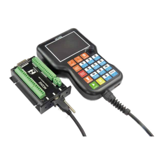
- Page 3 1.3 Appearance, Structure and Size of Product The NCH02 motion controller contains the handheld motion controller,wiring board,and HDMI digital high-definition transmission cable. The handheld motion controller and wiring board are communicated by 2 Meter 37 pins HDMI digital high-definition transmission cable which is shielding twisted-pair cable to avoid interference.
- Page 4 Picture 1-4 shows the 2 side pictures of NCH Wiring Board.The one side is for the MPG interface;and the other side is the LED indicators and USB port for the communication with the NCH02 Pendant Controller. There are two LED indicatiors,the red one is for the power,the green one is for the communications with the NCH Pendant controller.
- Page 5 1.4 Explanation of Abbreviations When operating the NCH02 Controller, the users will come across some English abbreviations. Here a list with explanations: FRO: Feed Rate Override SRO: Spindle Rate Override SRJ: Jog Speed Setting F: Feed rate, unit is mm/min S: Spindle Speed, unit rev/min.
- Page 6 GND, stepper control module and Input&Output module and Spindle control module share common GND, between the two sector there is photoelectric isolation. Inside of the board, there is GND as common-, no need to connect external power supply. Picture 2-2 Board Power Structure Page -5 NCH02 User’s Manual...
- Page 7 20W. The positive and negative connection of the power supply see as the silk printing. 2.3 The Input Ports INP1 INP2 INP3 INP4 INP5 INP6 INP7 INP8 Picture 2-2 The Input Ports definition Digital Dream Motion Controller Page -6 NCH02 User’s Manual...
- Page 8 And the E-stop,Micro switch,2 line proximity switch connection methods refered to Picture 2-4. Picture 2-3 Internal structure diagram of the input port Picture 2-4 Probe/Estop/ ordinary fretting switch input connection Picture 2-5 2 Lines Proximity Switch Connection Method Digital Dream Motion Controller Page -7 NCH02 User’s Manual...
- Page 9 3 lines Proximity Switch connection method as following Picture 2-6 shows. Brown cable connect with 12V,Black cable connect channel, blue cable connect with GND1. 3 lines proximity switch only NPN type is avaiable for the NCH02. Picture 2-6 NPN 3 lines Proximity Switch connection drawing...
- Page 10 50mA, and it is recommended to use a current amplification, for example ULN2803 chip. The Picture 2-9 is for external power relay method. Picture 2-9 General Output Port Connect with a Relay Digital Dream Motion Controller Page -9 NCH02 User’s Manual...
- Page 11 Ground and common end WHA- MPG A phase differential input negative terminal MPG B phase differential input negative terminal WHB- Y axis selection input A axis selection input X10IN 10 Rate Selection Input Digital Dream Motion Controller Page -10 NCH02 User’s Manual...
- Page 12 AIN1 is the input speed signal;COM is Comman Ground;X1 and X2 are configured to forward and reverse revolution. Picture 2-10 The Spindle Control Port Picture 2-11 The Spindle Control Port definition and wiring Digital Dream Motion Controller Page -11 NCH02 User’s Manual...
- Page 13 Z Axis/DIR- Z Axis/PUL- Z Axis/COM+ Y Axis/DIR- Y Axis/PUL- Y Axis/COM+ X Axis/DIR- X Axis/PUL- X Axis/COM+ Picture 2-12 Definition of Servo/Step Ports Picture 2-13 The wiring method with Stepper driver Digital Dream Motion Controller Page -12 NCH02 User’s Manual...
- Page 14 1: B axis rotates in reserve direction; 1: Increase the number clockwise; 2: Go To Zero funciton; 2: Decrease the number Counter-clockwise 3: Data 5 Input 3: Push the button to Confirm Digital Dream Motion Controller Page -13 NCH02 User’s Manual...
- Page 15 We will describe them one by one as below. Main Page Description The Picture 4-1 shows the Main Page of NCH02.It is divided into status column, coordinate display column, basic parameter column, and notification column. In total, it is divided into 20 sections in detail. Here...
- Page 16 Push Button Picture 4-2 Rotary&Push Button On Handheld Controller of NCH02 Before the description from No.5,we’d like to explain the Rotary&Push Button.Pls note the Picture 4-2 as above.By this button,it can decrease or increase the values by turnning the button,and push it to confirm.
- Page 17 Positive Limit of X(Y/Z) is Triggered X(Y/Z)-- LIMITED Negative Limit of X(Y/Z) is Triggered X(Y/Z)++ SOFT LIMITED Positive soft limit of X(Y/Z) is Triggered X(Y/Z)-- SOFT LIMITED Negative soft limit of X(Y/Z) is Triggered Digital Dream Motion Controller Page -16 NCH02 User’s Manual...
- Page 18 By turnning the rotary&push button to select the G-code file and press it to confirm the selection.Then the controller system will load the selected file.After the loading is finished,the controller software will shift to Main Page Automatically. Digital Dream Motion Controller Page -17 NCH02 User’s Manual...
- Page 19 As Picture 4-4 showed as above,the Motor Parameter configuration Page has a lot of column.There is a lot of the paramenter need to set up,also by rotary&push button.We marked the column from 1-17 and will decribe them one by one as following table. Digital Dream Motion Controller Page -18 NCH02 User’s Manual...
- Page 20 Active Level of backward direction limit.0=disable,1=enable Home Home Pin Setting.0=Disable;1=IN1,2=IN2...8=IN8. Home Level The HOME Signal ELectric Level.0=Low,1=High Home Dir HOME direction.0=Backward,1=forward. HKB Length Back off distance after Home,the unit is mm 0-100 Digital Dream Motion Controller Page -19 NCH02 User’s Manual...
- Page 21 M64 Pin Number Setting M64 Active Level Note:The Output Pin No. 0 indicates that the output closed,and the output Pin No. 1-5,the Mark No. is OUT1-OUT5. Output Active Electric Level Setting:1=Active,0=Not Active. Digital Dream Motion Controller Page -20 NCH02 User’s Manual...
- Page 22 Button buzzer switch, 0: close, 1: open EXT SIGNAL LEVEL Electrical level of Estop, 1=high, 0=low.EXT Signal effective for ESTOP/START/PAUSE/ZERO The pin of Estop,0 means close the signal,1=IN1,2=IN2..8=IN8.EXT Signal EXT SIGNAL PIN effective for ESTOP/START/PAUSE/ZERO Digital Dream Motion Controller Page -21 NCH02 User’s Manual...
- Page 23 The function can be select by turnning the rotary&push button.Select it and push the button the TEST ALL testing start.All modules are running. VERSION This column display the produts version information. Digital Dream Motion Controller Page -22 NCH02 User’s Manual...
- Page 24 As the following G code list and M code list shows,these G codes and M codes are supported by NCH02 Motion Controller. M Code Definition Quick positioning Spindle straightaway cut Spindle cut along the circle Spindle cut inversing the circle...
Need help?
Do you have a question about the NCH02 and is the answer not in the manual?
Questions and answers