Table of Contents
Advertisement
Quick Links
Advertisement
Table of Contents

Related Manuals for Digital Dream EC500


Summary of Contents for Digital Dream EC500
- Page 1 The version of 20180925 Mach3 Ethernet Motion Controller EC500 User’s Manual...
- Page 2 C on t e n t s 1. Brief Description of the EC500 Motion Controller ● ● ● ● ● ● ● ● ● ● ● ● ● ● ● ● ● ● ● ● ● ● ● ● ●...
-
Page 3: Safety Notes
The computer connects to the EC500 via a standard Ethernet cable.The cable may be shielded or unshield- ed.An advantage of the Ethernet compared to a USB is that the cable length maybe as long as 100 meters.The maximum length for a USB cable is 5 meters,and that is pushing it in a noisy working environment.Another... - Page 4 3. Physical Installation of the device(Unit:mm) The EC500 motion controller is with the sealed shell structure,there are 4pcs mounting holes around the controller.We can fix 4pcs 4mm diameter holes at the cabinet,and install the controller into the cabinet. 21 mm...
- Page 5 4. Controller EC500 Power Solution The power supply solution in the field of the Industrial automation is always very complicated, there is a lot of the GND, now we descript the structure of the power structure as below: The power structure as the Picture 4-1,Power supply input and Ethernet port share common GND, stepper control module,Input&Output module,Spindle control module and MPG Port share common GND, between the...
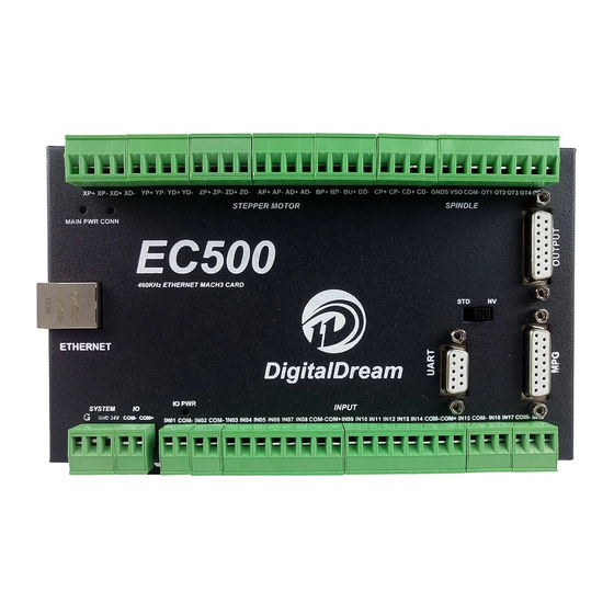
- Page 6 3 : Spindle Control Output Port 4 : Gerneral Output Interface 5 : MPG Port 6 : Functional Switch for MPG:Standard MPG or Digital Dream MPG 7 : Serial Extend Port 8 : Input Port:Limit/Home/Probe and so on 9 : IO Power Port...
- Page 7 5.1.1 Setup with direct connection to a LAN network card. Firstly connect the EC500 controller to PC by the ethernet cable. To Setup the connection with direct cable connection click on the name of the connection and on the pop-up window press the Properties button.Please note that for this action to work the user must have administrator...
- Page 8 Subnet Mask: 255.255.255.0 Picture 5-3 EC500 Ethernet Communication Setup IP No. 5.1.2 Setup with direct connection via switch/router. To Setup the connection with connection via a switch or router device click on the name of the connection and on the pop-up window press the Properties button.Please note that for this action to work the user must have administrator rights in Windows account.On the popup window find and select the ‘Internet Protocol Version...
-
Page 9: Stepper/Servo Motor Control Interface Connection
B Axis Direction Output - C Axis Pulse Output + C Axis Pulse Output - C Axis Direction Output + C Axis Direction Output - Picture 5-5 EC500 Stepper/Servo Mark and description Digital Dream Mach3 Motion Controller Page -7 EC500 User’s Manual... -
Page 10: Spindle Control Output Port
RUN and STOP, we need to connect X2 to OUT2. AIN1 Picture 5-6 EC500 Spindle Control Setup VSO connects to Speed adjustment which defined by voltage 0-10V. The relationship Max. Spindle speed and current spindle speed is as below: VSO(Output Voltage)=10*current spindle speed(S)/Maximum Spindle Speed(Max.S). -
Page 11: General Output Interface
Picture 5-7 EC500 Spindle Motor Max Speed Setting 5.4 General output interface As the Picture 5-1 showed. the marked No. 4 is General output interface. This is a DB15 port. Picture 5-8 General Output DB15 Pin No. PIN No. Mark... - Page 12 The general output interface has a built-in relay drive circuit, which can be directly connected to less than the 100mA relay. Reference Picture 5-10. for wiring with relay, using output 6(Pin No.2). COM+ OUT6 Picture 5-10 Solid Replay Connection Digital Dream Mach3 Motion Controller Page -10 EC500 User’s Manual...
- Page 13 5.5 Function Switch for MPG and Connection for MPG As the Picture 5-1 showed, the marked No.6 is the switch for the options of two type MPG.For EC500,it can supply both standard MPG and NV-MPG which is made by our company Digital Dream. The Marked No.
-
Page 14: Serial Extend Port
3 lines Proximity Switch connection Picture 5-14 and Picture 5-15, brown cable for Proximity switch connect with 12V,Black cable connect channel, blue cable connect with GND1. Pls note Only support NPN typel 3 lines proximity switch. Digital Dream Mach3 Motion Controller Page -12 EC500 User’s Manual... - Page 15 Picture 5-12 Internal structure of Input interface Picture 5-13 Probe/Estop/ and other switch input connection Digital Dream Mach3 Motion Controller Page -13 EC500 User’s Manual...
- Page 16 Picture 5-14 NPN 3 lines Proximity Switch connection drawing Picture 5-15 NPN 3 lines Proximity Switch Connection Example Digital Dream Mach3 Motion Controller Page -14 EC500 User’s Manual...
-
Page 17: Power Supply For Controller System And Power Supply For Io Port
If the controller and IO power supply are configurated in right way,the Main Power LED and IO Power LED turn to Red. The LED marked “CONN” represents the status of the communicaton with Mach3 software.If a link has not been established,the LED will not light. Digital Dream Mach3 Motion Controller Page -15 EC500 User’s Manual... -
Page 18: Mach 3 Configuration
When you purchase our product, we will supply a software package in the U-disk, which contains “Digit- alDream” PlugIn,and the EC500 Manual. In your computer which you will run the EC500 controller,you must already installed the Mach 3 Software,and now pls copy the PlugIn in to C:\Mach3\PlugIn.(If the user install the Mach 3 software in C-disk.) 6.2 Open Mach3 Software and connect with right PlugIn file... - Page 19 After Click “OK”,it will popup a window for the options of DLL file as below,pls choose “Digital Dream” as below.Then press OK. If you do not want to the dialog box to show again any more, select ‘Don’t ask me this again’.If connect successfully,Status bar will show “EC500 device is connected to your computer”.
-
Page 20: Motor Tuning And Setup
Don’t forget to save the data when you finished the data setting of every axis.For example,you click Z Axis,and save all the datas into the column,then you must click “SAVE AXIS SETTING”,then the datas can be saved. Digital Dream Mach3 Motion Controller Page -18 EC500 User’s Manual... - Page 21 Input Signals). While you could use a single input for your X, Y, Z, and A homes, it is much better to have them as separate inputs! Our EC500 controller has plenty of inputs available and it allows Mach to home all of your axes at the same time if you wish (although you typically have your Z axis home after the rest of your axes so you don't crash your head).
- Page 22 Here you can configure according to your actual needs the corresponding function. Optional Function include XYZABC 6axis’s Upper and lower limit、XYZABC 6axis’s HOME point. We set upper limit and home of XYZA to 3456 corresponding IN3/IN4/IN5/IN6 of the Controller board. Digital Dream Mach3 Motion Controller Page -20 EC500 User’s Manual...
- Page 23 Here by our controller we already define all the Output Ports to Port No. 2. All Output Ports are defined to Port No. 2. Spindle setting corresponds to the output configuration Digital Dream Mach3 Motion Controller Page -21 EC500 User’s Manual...
-
Page 24: Mpg Settings
Then the following windown will popup,click the “CONFIG” of the DigitalDream dll as following,there will be the selection windows for NV-MPG and standard MPG.The user have to select the right MPG type as their request. Digital Dream Mach3 Motion Controller Page -22 EC500 User’s Manual... - Page 25 Go to Mach 3 and Menu -> Config -> Ports & Pins -> Encoder/MPG’s as following. Then to active the MPG function, you can use the hand pulse, under the main page, click TAB to active MPG panel, refer to the following Picture: Digital Dream Mach3 Motion Controller Page -23 EC500 User’s Manual...