Table of Contents
Advertisement
Quick Links
Advertisement
Table of Contents

Related Manuals for Digital Dream DM500T3


Summary of Contents for Digital Dream DM500T3
- Page 1 Handheld Motion Controller For Engraving Machine DM500 User’s Manual...
-
Page 2: Introduction Of Product
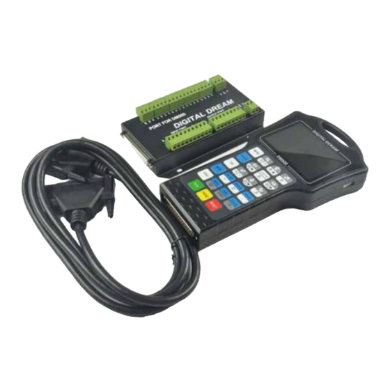
1 DM500 Motion Controller Introduction 1.1 Introduction of Product Digital Dream has a 20 years history in the numerical control industry, specializing in the research, devel- opment and production of various CNC (Computer Numerical Control) systems. DigitalDream aims to combine high quality and high reliability with affordability. - Page 3 The wiring board can be installed by DIN linearguide ways No. C45. Picture 1-1 DM500 Pendant Size 88 mm The wiring board Size Digital Dream Motion Controller Page -2 DM500 User’s Manual...
- Page 4 The front panel consists of 23 user keys and the 3.5’’ (480*320 ) LCD. 3.5'' Screen 23 user’s keys 37 pins Male Interface 37 pins Female Interface Digital Dream Motion Controller Page -3 DM500 User’s Manual...
-
Page 5: Explanation Of Abbreviations
In case of a problem, press the E-stop at once to avoid damage to humans, animals and the equipment. High voltage danger. The CR8-500 is connected to18-32V DC. Obey and follow the electricity safety rules of your country when connecting this equipment. Digital Dream Motion Controller Page -4 DM500 User’s Manual... - Page 6 2 Wiring Wiring Board Drawing Page -5...
- Page 7 2. 24V GND is the power supply for the controller,COM+ and COM- is the common terminal for Input and Output ports. 3. The Low voltage for input signal is effective.By default it is the NPN switch. 4. The pulse and direction signal is differential output. Digital Dream Motion Controller Page -6 DM500 User’s Manual...
- Page 8 Y02/Y03/Y03 are for settings of spindle 8 different speeds. Open-collector output,installed,Current:500mA,Voltage:30V Alarm Output Cooling output Port (M8/M9) Lubrication output Port (M10/M11) Receive Port of communication Send Port of Communication RS232 Ground of Communication Port Digital Dream Motion Controller Page -7 DM500 User’s Manual...
- Page 9 Switch Power Switch Power Suply 2 Supply 1 +24V +24V COM- COM+ Main controller use the same power supply with Input/output ports.(no recommended). DB37 Filter Switch Power Supply +24V COM- COM+ Digital Dream Motion Controller Page -8 DM500 User’s Manual...
- Page 10 When the Inputs and Output Ports (COM+ COM-) share the same Power supply with the controller: Motion Controller COM+ COM- Motion Controller COM+ Proximity Switch Normal Open Mode COM- It’s the best to use the first independent power supply method.Logic low Effective.NPN normal open proximity switch. Digital Dream Motion Controller Page -9 DM500 User’s Manual...
- Page 11 There is 7 output pins,the electric circuit just as the above file showing. When you connect the relay,pls install a fly-wheel diode as the drawing showing. The first Independent power supply method is recommended. Digital Dream Motion Controller Page -10 DM500 User’s Manual...
- Page 12 Shielding Cable Y,Z,A axis wiring are same as X axis; The controller use differencial output methods,And The Max. Output Frequency is 500Khz; Cannot connect as Common anode and cathode; Digital Dream Motion Controller Page -11 DM500 User’s Manual...
-
Page 13: Definition Of Keys
3. Definition of keys The Panel Keys showed as the photo below: Digital Dream Motion Controller Page -12 DM500 User’s Manual... - Page 14 1: Negative movement of Y Axis; Reset and E-STOP. 2: Data 2 input; Shift between Reset and Ready 3: Cursor moves down. 1: Negative movements for A Axis; 2: Data 3 Input. Digital Dream Motion Controller Page -13 DM500 User’s Manual...
-
Page 15: Menu Tree Structure
4: Total working time 5: Current operation Rights 6: The information page 7: Main Page 8: File Page 9: Parameter Page Menu tree structure Menu Main page File page Para page Digital Dream Motion Controller Page -14 DM500 User’s Manual... - Page 16 Y Find Mach Zero Super Admin Password Setting Z Find Mach Zero Probe Software Registration Start Line Lifetime Setting Unlock Break Lifetime Setting Nearest Point Mul Origin Save origin Load Origin Digital Dream Motion Controller Page -15 DM500 User’s Manual...
- Page 17 6. Current workpiece Coordination: G54/G55/G56/G57/G58/G59 workpiece coordination;Mach Coordi- nation; 7. Manually High/low speed; 8. Output signal status; 9. Input signal status; 10. Version information and Programming date; 11. Machining information: G code information when automatically machining;Errors. Digital Dream Motion Controller Page -16 DM500 User’s Manual...
- Page 18 The Name of folders and files, the size of files and the time and date of manipulation. The blue strip indicates the current valid target location. Digital Dream Motion Controller Page -17...
- Page 19 G code and go back to the Main Page for processing the G-code file. 4.4.2 The Operation of the File Page When at the File Page,and Press the key and the page pop up the list as below: Digital Dream Motion Controller Page -18 DM500 User’s Manual...
- Page 20 Index No. Press to select the parameter and start to write it.Press the data keys and press to save the values;if press the key then cancelled saving. Digital Dream Motion Controller Page -19 DM500 User’s Manual...
- Page 21 4.5.2 The Operation of the Parameter Page When at the Parameter Page,and Press the key and the page pop up the list as above. About the File management,we will describe it in next chapter. Digital Dream Motion Controller Page -20 DM500 User’s Manual...
-
Page 22: System Status
When the pulse equivalent is big,the machining precision is high.And pulse equivalent determin the Max. feed speed,the relationship is: Max feed speed(mm/min)=(1/pulse equivalent(p/m)) x frequency(p/s) x 60 When the controller Max. frequency is 500Khz,and the pulse equivalent is 1000p/mm,the machine Max. feed speed is 30m/min. Digital Dream Motion Controller Page -21 DM500 User’s Manual... - Page 23 • The speed can be set at “SJR” or parameter adjustment. 5.2.3.2 Continuously High speed feeding Feeding to one direction at high speed. Condition: • Controller is in READY status; • Operate mode is CONT. Digital Dream Motion Controller Page -22 DM500 User’s Manual...
- Page 24 • Press the start key; • the controller will start to process the G-code file selected; • The controller status shift from “READY” to “BUSY” • When the work finished,the controller status back to “READY”. Digital Dream Motion Controller Page -23 DM500 User’s Manual...
- Page 25 The controller supplies G54-G59 6 kinds workpiece coordination and one MACH machine coordina- tion.Before running a G code file,the users need to decide one work piece coordinate. Conditions: • Controller is in READY status; • The screen go to “Main page”. Digital Dream Motion Controller Page -24 DM500 User’s Manual...
- Page 26 • Press the key and then ,then Press to confirm to save the Origin Position • Successively press the Key and then Mul Origin Load Origin ,then press to load the origin position. Digital Dream Motion Controller Page -25 DM500 User’s Manual...
-
Page 27: About Tools
9) If the user don’t change the origin positon of the work piece,and when the user changed different length cutters,just measure the thickness of the tool sensor and take the new data. 10) If the Z Axis Origin(Zero) position is changed,just repeat the action from 6-9. Digital Dream Motion Controller Page -26 DM500 User’s Manual... - Page 28 4) Go to Parameter 69 and type in the thickness of the tool sensor.You should know it in advance. 5) Move the cutter above the tool sensor manually; 6) Press the key ,the press to probe. Probe Digital Dream Motion Controller Page -27 DM500 User’s Manual...
- Page 29 Conditions: • Controller is in READY status; • The screen go to “Main page” Digital Dream Motion Controller Page -28 DM500 User’s Manual...
- Page 30 F value is: Real time feed speed=F(Feeding Value) x FRO Conditions: • Controller is in READY status; • The screen go to “Main page” Digital Dream Motion Controller Page -29 DM500 User’s Manual...
- Page 31 Max spindle speed is 24000RPM,and the S value is 3,then the spindle speed is 24000*3/8=9000RPM. Press the key or change the value of S. Press the Key to Start or Stop Spindle Digital Dream Motion Controller Page -30 DM500 User’s Manual...
- Page 32 M501/M601 Spindle Speed Pin 2 M703/M803 Z Home M501/M601 Spindle Speed Pin 3 M704/M804 A Home M501/M601 Alarm Output M705/M805 Probe M501/M601 M506/M606 M706/M806 E-Stop M501/M601 M507/M607 M707/M807 Start/Probe M708/M808 Pause Digital Dream Motion Controller Page -31 DM500 User’s Manual...
- Page 33 Para# 423,Define the External input 1 or not: No For Example: M706: Wait for X06 input connection G60 G01 X100: Run to X100 position M806: Wait for X06 disconnection G90 G01 X200: Run to X200 position Digital Dream Motion Controller Page -32 DM500 User’s Manual...
-
Page 34: Files Management
• At the subdirectory of the INSTALL file,there is no file which can named as “INSTALL” • After updating successfully,delete the INSTALl file from U-disk,or everytime restart the controller, it will update automatically. Digital Dream Motion Controller Page -33 DM500 User’s Manual... -
Page 35: Parameter Management
• Press ,type in the admin password,and enter Restore Para U Pls note the backup data should be saved into the “setting” file at the root directory of U-disk in Advance. Digital Dream Motion Controller Page -34 DM500 User’s Manual... - Page 36 Please use the setting value of default parameter under the situation of not understanding the actual function of this parameter. Page -35 Digital Dream Motion Controller DM500 User’s Manual...
-
Page 37: Password Setting
• Controller is in READY status; • The screen go to “Para page” Operation: • Press ,type in the old password and new password,click “YES”. Password Setting Pls note the window as below: Digital Dream Motion Controller DM500 User’s Manual Page -36... - Page 38 #265 stop Acceleration of Z in M_Ctrl mode 1200 0~2000 mm/s larger #266 stop Acceleration of A in M_Ctrl mode 0~2000 1200 degree/s Digital Dream Motion Controller Page -37 DM500 User’s Manual...
- Page 39 Electric Level of E-stop On Box BOOL 1: High; 0:Low #446 Definition of the External Input 2 BOOL 2/1/0 0:Null,1:Start; 2:Probe #447 Definition of the External Input 3 BOOL 0:Null,1: Pause Digital Dream Motion Controller Page -38 DM500 User’s Manual...
- Page 40 Y axis in fixed mode 0-9999 Mach(ine) coordinate system Height of Z axis before the XY move initial Z axis in fixed mode 0-9999 under the Mach(ine) coordinate system Back off distance after probing 0~200 Digital Dream Motion Controller Page -39 DM500 User’s Manual...
- Page 41 0.002 0.002-0.01 circle of interpolation #250 enable of draw tool road BOOL 0:disable 1: enable #253 mode of draw BOOL 0:statue mode 1:line mode #495 Interpolation period 0.005 0.002~0.01 Digital Dream Motion Controller DM500 User’s Manual Page -40...
- Page 42 Inch Input: G20; (G20、G21) Metric Input: G21 Reference Point G28 IP_; Middle Point Return To Reference Point Starting Point D_ ; Tool Radius compensation (G40~G42) D: Offset No. of Tool; G40: Cancel; Digital Dream Motion Controller Page -41 DM500 User’s Manual...
- Page 43 M601-M607(The detail see the Page 32) Y01-Y07 Output Close M701-M708(The detail see the Page 32) X01-X08 Input connection and delay M801-M809(The detail see the Page 32) X01-X08 Input disconnection and delay Digital Dream Motion Controller Page -42 DM500 User’s Manual...
Need help?
Do you have a question about the DM500T3 and is the answer not in the manual?
Questions and answers
The manual is old