
Related Manuals for Stratasys uPrint


Summary of Contents for Stratasys uPrint
- Page 1 Plus ® ® Personal 3D Printers User Guide 207203-0002 207203-0002...
-
Page 2: Legal Notice
Legal Notice © 201 1 Stratasys, Inc. All rights reserved. The Stratasys, Dimension, uPrint, uPrint Plus and information in this document is subject to CatalystEX are registered trademarks of change without notice. STRATASYS, INC. Stratasys, Inc. MAKES NO WARRANTY OF ANY KIND ABSplus is a trademark of Stratasys, Inc. -
Page 3: Table Of Contents
Table of Contents 1 Introduction..........................1 How to use this guide ....................1 Learn More!......................1 Safety precautions ....................2 2 Overview ..........................3 Finding more information ..................9 3 Setup ............................10 Installing software ....................10 Networking the printer ...................10 Establishing network communication with the printer ..........11 Installing Firmware on printer..................14 Adding the second Material Bay ................14 4 Operation ..........................19... - Page 4 Facility specifications .....................61 Workstation specifications..................62 Power specifications ....................62 Environmental specifications ...................62 Acoustic specifications ...................62 10 Supplemental Information......................63 Stratasys Limited Warranty Statement ..............63 Declaration of Conformity ..................65 Regulatory and environmental information ..............66 11 Appendix..........................A1 Uninterruptible Power Supply (UPS) Use and Installation..........A1...
-
Page 5: Introduction
With Soluble Support Technology (SST), your completed parts are quickly available for review and test. uPrint and uPrint Plus are an innovative combination of proprietary hardware, software and material technology. -
Page 6: Safety Precautions
Safety precautions The following precautions ensure the proper use of the printer and prevent the printer from being damaged. Follow these precautions at all times. • Use the power supply voltage specified on the nameplate. Avoid overloading the printer’s electrical outlet with multiple devices. •... -
Page 7: Overview
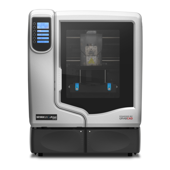
Windows 7 platforms. uPrint builds a maximum part size of 203 x 152 x 152 mm (8 x 6 x 6 in). uPrint Plus builds a maximum part size of 203 x 203 x 152 mm (8 x 8 x 6 in). Each material carrier contains 492 cc (30 cu. - Page 8 Figure 1 Front and left side view of printer. Front view Left side view Display Panel Material Bay, Support Side Optional Material Bay, Support Side Optional Material Bay, Model Side Material Bay, Model Side Power ON/OFF Switch...
- Page 9 Figure 2 Interior chamber - front view Extrusion Head Tip wipe assembly Purge bucket Z stage platen Modeling base retainers (x2) Modeling base Z stage lead screw Z stage guide rods Extrusion Tips...
- Page 10 Figure 3 Rear view of printer Model Material Y Connector Support Material Tube Model Material Tube UPS Connection AC Power Cord Connector Material Bay Cable Connector Circuit Breaker RJ-45 Network Connector Material Bay Diagnostics Cable Connector Optional Model Material Tube Material Bay Communications Cable Optional Material Bay Optional Material Bay Communications Cable...
- Page 11 Figure 4 Material carriers Model material carrier Support material carrier Figure 5 Modeling base Modeling base CAUTION: DO NOT reuse modeling bases. If a modeling base is reused, calibration errors, poor part quality, and loss of extrusion may occur. Additional modeling bases are available from your reseller.
- Page 12 Figure 6 Startup Kit contents Crossover cable (orange) Network cable (blue) Tip replacement kit (A. Support tip B. Model tip C. 8 Tip shields D. 4 Tip wipe assemblies) Model material spool CatalystEX CD 1/8 inch T-Handle wrench (red) System Software CD User Guide CD Support material spool 7/64 inch T-Handle wrench (yellow)
-
Page 13: Finding More Information
Finding more information CatalystEX Online Help Simple operating instructions for CatalystEX are available in CatalystEX Dynamic Help. You can also see CatalystEX Help from the menu bar - Help>Contents World Wide Web Additional information is available at: http://www.dimensionprinting.com/uprint/customerinfo.html... -
Page 14: Setup
Set up the printer and material bay(s) per assembly instructions included with printer. Installing software There are two software programs that work with uPrint and uPrint Plus: CatalystEX, installed on your workstation, processes the STL files for printing and communicates with the printer from your workstation. -
Page 15: Establishing Network Communication With The Printer
Establishing network communication with the printer You will need to establish network communication between your workstation and printer before you can send files to be built. How you establish this communication with an IP address is dependent upon how your network and workstation are configured. If your network is configured for DHCP (Dynamic Host Configuration Protocol), your DHCP server will automatically assign a Dynamic IP address to your printer. - Page 16 Setting the static network in Windows XP: From your workstation open the Control Panel and double click on Network Connections. Right click on Local Area Connection and then left click on Properties. Select Internet Protocol (TCP/IP) from the list. Click on the Properties button. Click on the Use the following IP address option.
- Page 17 Setting the static network on printer: Obtain your static network address from your Network Administrator. From Idle (or Ready to Build), press Maintenance on the display panel. The display will show Maintenance and the software version. Press System. Press Set Network. The top window displays: Network Admin - Static IP Address; UDN. Press Static IP to display default settings.
-
Page 18: Installing Firmware On Printer
Select your printer from the drop down list then click the Update Software button. Navigate CatalystEX to the directory where the firmware file is located and select the uPrint.upg file for uPrint or select the uPrintPlus.upg file for uPrint Plus. Firmware will now begin to download to the printer. - Page 19 Remove the material carriers by first pushing them in to unlatch and then pulling them outwards. Place the carriers on a flat stable surface. CAUTION: Do not push the material through the material guide back into the carrier, doing so can cause material to break or become tangled. Open the carriers.
- Page 20 Figure 9 Positioning material bays With 2 people, position the printer on to the top of the material bays. Be sure the feet and pins are properly aligned. See Figure 10. Figure 10 Positioning printer Remove the black plugs from the model and support Y blocks by pushing in on the coupler rings and pulling outward.
- Page 21 Figure 12 Connecting the short material tubes Connect the long red striped material tube (M2) from model (M) coupler of lower material bay to right side of model Y block by inserting firmly into red couplers. Gently pull the tube to ensure it is properly inserted.
- Page 22 Connect the power cable, network cable and UPS cable if used. Switch the circuit breaker to the ON position. Power the printer ON at the power switch. After the printer has booted up, you may need to reload the printer firmware. If the printer displays “Send Upgrade from Workstation”, See “Updating printer firmware:”...
-
Page 23: Operation
Main display window Lower display windows The uPrint and uPrint Plus display panel and keypad consist of a multiple-line LCD window with two buttons used for scrolling through messages and four single-line windows, each with one button for making selections. The top line in the upper window always shows the printer status. -
Page 24: System Firmware Overview
System firmware overview • Idle: If there is no part being built and no part in the build queue, the display will show that the printer is Idle. • Wait for Part or Start Part: If the printer is in Idle and the build queue is empty, you can set it to wait for a part. -
Page 25: Catalystex Overview
CatalystEX overview • General tab: This section is where you can select the model fill, support style, change the STL units and STL scale. • Orientation tab: This section allows you to rotate, resize and auto-orient your parts. You can also change the view and insert a pause. -
Page 26: Processing Your Stl File For Printing
Navigate to and select the STL file that you have created. Selecting layer resolution: Layer resolution can be changed on the uPrint Plus printer. Changing layer resolution will affect surface finish and build times. Selecting a smaller layer resolution creates a smoother surface finish, but takes longer to build. - Page 27 Selecting the scale of your STL file: Before you process a part for printing, you can change the size of the part within the build envelope. Every part has a pre-defined size within the STL file. After you have opened the file you can change the size of the part produced from the STL file by changing the scale.
-
Page 28: Building A Part
Adding your STL file to the pack: The Add to Pack button is found on the General, Orientation and Pack tabs. When you click on the Add to Pack button, CatalystEX will add the file that is currently in the preview window (General tab or Orientation tab) to the pack preview window (Pack tab). -
Page 29: The Display Panel During Build
The display panel during build The top two lines of the display panel will show the printer status. See Figure 18. The bottom line of the display panel will show the amount of model and support material that remains in the carriers. Figure 18 Display panel during build Single material bay... -
Page 30: Canceling A Build
Canceling a build You can cancel a build at any time while the part is building. From the display panel press Pause. Once the printer stops building, press Cancel Build. The display will ask Are you Sure? Press Yes. The display will show Build Stopped followed by the file name. You will then be prompted to remove the part and replace the modeling base. -
Page 31: Removing Support Material
Removing support material uPrint and uPrint Plus use soluble support material which is designed to dissolve in a soap and water based solution. Your part is left with a smooth and clean finish with the fine details intact. The soluble support material can be removed by hand with relative ease, but is designed to be dissolved from your parts for hands free finishing. -
Page 32: Replacing Material For Single Material Bay
Replacing material for single material bay From the display panel press Material... The display will show Add/Remove and S1(remaining%) and M1(remaining%). Asterisks will mark the currently active material bays (the material bays that are currently loaded to the head). Press Unload... Select Unload both, Unload Model or Unload Support. -
Page 33: Replacing Material For Dual Material Bays
Replacing material for dual material bays From the display panel press Material... The display will show Add/Remove and S1(remaining%), S2(remaining%) and M1, M2 (remaining%). Asterisks will mark the currently active material bays (the material bays that are currently loaded to the head). Press Unload... -
Page 34: Material Bay Leds
Material bay LEDs The table below will show the status indicated by the LEDs. Material currently loaded to the head No carrier present Carrier present and ready to be loaded Blinking Carrier needs replacement (is empty or has an error) Replacing material spools Removing a spool of material from the carrier: Place the carrier on a flat stable surface. - Page 35 Figure 22 Rewinding the material spool Using a cutters, cut the excess 2 inches (50mm) of material from the material guide, leaving a blunt end. Locate the two material retaining clips on the carrier. See Figure 23. Figure 23 Material retaining clips Material retaining clips Place the material guide in the material guide slot on the spool.
-
Page 36: Auto Power Down
Figure 25 Installing material retaining clips Place clip and push down to lock in place Remove the material spool from the material carrier. See Figure 26. Figure 26 Properly installed material retaining clips. Place the material spool in the storage bag that came with the material carrier. Note: When not loaded in the printer, always store material spools in the material carrier or the storage bag that came with the carrier to prevent... -
Page 37: Resuming Operations From Standby Mode
From the display panel press Resume. Updating printer firmware: Check http://www.dimensionprinting.com/uprint/customerinfo.html for printer firmware updates. If there is an upgrade to the printer firmware, download the upgrade and install on the printer. Installing the firmware: From the printer display panel, press Maintenance. -
Page 38: Maintenance
Maintenance Startup kit tools The startup kit contains a set of tools used to help you maintain the printer. The following is a list of the tools contained in the startup kit. • Needle nose pliers • T-Handled allen wrench - 1/8 inch •... -
Page 39: 500 Hour Maintenance
500 Hour maintenance Preventive Maintenance Alerts will be displayed on the workstation at the 500 hour time interval as a reminder to perform preventive maintenance. See Figure 27. Figure 27 Preventive Maintenance Alert Tip wipe assembly The tip wipe assembly should be replaced approximately every 500 hours. Completely power down the printer. - Page 40 Figure 29 Replacing the tip wipe assembly Place the new tip wipe assembly over the two mounting posts making sure the assembly is fully installed. See Figure 30. Figure 30 Installing tip wipe assembly Power the printer back up.
-
Page 41: Tip Shield Replacement
Tip shield replacement Tip shields can become worn or damaged over time. This can have a negative impact on the surface finish and detail of models. Replace the tip shields every 500 hours. Figure 31 Tip Shield damage New shield Worn shield Enter Head Maintenance. - Page 42 Figure 33 Tip Shield removal Tip plate Insert small standard screwdriver to pry tip shields from tips. Tip shield Clean the tip using the wire brush supplied with the Startup Kit to remove any debris. See Figure 34. Figure 34 Clean tips with wire brush Clean the tips using a wire brush.
-
Page 43: Remove Debris From The Filament Present Switch
Figure 35 Tip Shield installation Replace head cover. Note: If the head cover is not replaced the printer may not function properly. Exit Maintenance, press Done until back at Idle. Remove debris from the Filament Present switch There may be a time when the Filament Present switch needs to be cleared in addition to the 500 hour maintenance. - Page 44 Figure 36 Filament Present Switch location Support side Filament Present Switch Model side Filament Present Switch Obtain a can of compressed air. Insert the canned air extension tube to its spray nozzle. Align the canned air extension tube with the entrance hole of the Filament Present Switch. See Figure 37.
-
Page 45: 2000 Hour Maintenance
2000 Hour maintenance Tip replacement and calibration A Preventive Maintenance Alert will be displayed after 2000 hours of run time informing you that tips need to be replaced and calibrated. See Figure 38. Figure 38 Preventive Maintenance Alert Note: Tips can also be damaged by improper care while performing maintenance in the area around the tips. - Page 46 Figure 39 Head cover tab locations Press tabs in to remove Head cover head cover Remove tips Use 7/64 T-Handle Allen wrench to loosen the heater block screws three to four full turns counterclockwise - or until the top of the screws are flush with the metal cover.
- Page 47 Figure 41 Remove the tips Pull tips down to remove Repeat for second tip if necessary. Installing tips: Place the tip shield on the tip. Be sure to install the proper tip. See Figure 42. Figure 42 Tip shield alignment Slotted end Slotted end Align the tip shield so the slotted end is...
- Page 48 Figure 43 Install the tips Use needle nose pliers to grasp the stainless steel shield of the tip. Pull the tip shield toward you, then lift up to install the tip. Push the tip toward the back of the printer once it is all the way up against the heater block. Verify the tip is fully inserted into the heater block and that the stainless steel shield is aligned.
- Page 49 Replace head cover and close the printer door. Note: If the head cover is not replaced the printer may not function properly. The printer will display Tip Maintenance - Tips Replaced? - press Yes to begin material load. The printer will display Load Model - Replace Both Carriers (flashing).
- Page 50 When you are satisfied with your X offset value, Select Y and repeat steps A- D to identify and input the required Y Tip Offset adjustment. Figure 45 Example XY Tip Offset Part. This example requires an adjustment of X = + 2, Y = - 4 Select Done after you have input the X and Y offsets.
-
Page 51: Chamber Light Bar Replacement
Chamber light bar replacement Power down the printer. Locate the wiring harness leading away from the top of the light bar. Disconnect the light bar from the wiring harness by squeezing the wiring harness clip while pulling down. Remove the light bar by removing the three attachment screws (top, middle, bottom) - use the 7/64 T-handle wrench supplied in the startup kit. -
Page 52: Troubleshooting
Troubleshooting Troubleshooting Problem Recommendation Verify power cord is securely plugged in. No power Verify that the circuit breaker (at rear of printer) and the power switch (on left side panel of printer) are both in the ON position. Verify AC power is present at wall outlet. Material not extruding Material may be clogged in tip see “Clogged tip”... -
Page 53: Fault Determination Codes
Error message on display panel Recommendation Remove the carrier and verify material is coming out of the material guide. Material Error Filament broken Verify material pulls freely from the carrier. Verify the material tubes are free of material. Reload material. Remove the carrier and verify material is coming out of the material guide. -
Page 54: Cycling Power
Cycling power Turn the power switch to the OFF position. The display will show Shutting Down. After the printer has cooled down enough to shut down, the display will go blank. When the display is blank and the printer has shut down, turn the circuit breaker to the OFF position. -
Page 55: Clogged Tip
Clogged tip Occasionally, a tip may clog with material. This will often result in a loss of extrusion (LOE). A clogged tip will prohibit material load and part building. Remove the head cover by pressing the tabs in and pulling away from the head. See Figure 47. -
Page 56: Material Jam
Material Jam Occasionally, material may become jammed in the head. The printer will notify you of a material jam through a message shown on the display panel. If a material jam is detected, follow these steps to clear the jam. From the display panel, press Continue. - Page 57 Figure 49 Tip inlet locations Support tip inlet Model tip inlet Press Select Drive and choose the drive that may have the clogged tip. Press Forward, the drive wheel will turn the selected drive forward. Press Blower Off, this will turn the head cooling fan off for 10 seconds, allowing the tip to heat up beyond operating temperature.
-
Page 58: Recovering From Loss Of Extrusion
Recovering from loss of extrusion Note: It is recommended that you read and understand this entire procedure before performing any of the work. Enter Head Maintenance mode. From Idle, press Maintenance. Press Machine. Press Head. The head will heat up to operating temperature which will take approximately 3 minutes. - Page 59 Figure 51 Head Components Toggle spring Support side idler wheel Model side idler wheel Heater block Drive wheel Toggle bar Figure 52 Toggle bar in neutral position Remove any excess material found around the head area. Note: Material fed to the tip can sometimes jam causing a build-up of material under the head cover.
- Page 60 For easier access to areas that may need to be cleaned, move the material idler wheels out of the way (there is one idler wheel for support material and one for model material, Figure 51.) Note: Move only one idler wheel assembly at a time. Finish cleaning around the moved wheel and restore it to its normal position before moving the other idler wheel.
- Page 61 Figure 54 Holding access space open - model side shown Insert 1/8 inch T- Handle into fixture hole. Ease pressure on the 7/64 T-Handle Allen wrench to carefully return the leveraged idler wheel back toward its original position - until the idler assembly is resting against the 1/8 T-Handle Allen wrench.
-
Page 62: Support
Customer Support Visit http://www.dimensionprinting.com/uprint/customerinfo.html for the following: • How to order consumable parts for your uPrint or uPrint Plus printer. • Technical support contact information for your uPrint or uPrint Plus printer. • Technical support for your SST tank. •... -
Page 63: Recycling
Recycling Recycle all materials per your local recycling guidelines. Figure 55 Recycling Codes System Component Materials Recycling Code X (2) and Y (4) guide rod restraints (orange) Model material guide (red, both halves) Support material guide (black, both halves) ACETAL Material retaining clip (blue) Material Carrier (clear top, black bottom and bottom cover. -
Page 64: Removing The Eeproms From The Material Guides
Removing the EEproms from the material guides Open the model and support material carriers and remove the material guides. With a small standard screwdriver, pry the two material guide halves apart. See Figure 56. Figure 56 Pry the model material guide apart Pry apart with a small standard screwdriver Recycle the EEPROM per your local electronics recycling guidelines. -
Page 65: Printer Specifications
Printer Specifications The information in this section is applicable to both uPrint and uPrint Plus printers. Physical specifications Height 762 mm (30 in) Width 660 mm (26 in) Depth 660 mm (26 in) Weight 59 kg (130 lbs) Material bay height... -
Page 66: Workstation Specifications
Workstation specifications Operating System Microsoft Windows XP, Microsoft Windows Vista or Microsoft Windows 7 Processor Minimum: 2.4 GHz Faster processors will shorten job processing times Minimum: 1GB (2GB for Windows Vista or Windows 7) Recommended: 2GB (3GB for Windows Vista or Windows 7) Hard Disk Installation: 90MB Monitor graphics reso-... -
Page 67: 10 Supplemental Information
® and uPrint ® Plus Products and/or out of this limited warranty, even if Stratasys or its' designated representative have been advised of the possibility of such damages or claims. - Page 68 NEITHER STRATASYS NOR ANY AUTHORIZED RESELLER MAKES ANY OTHER WARRANTY OF ANY KIND, EXPRESS OR IMPLIED, INCLUDING ANY IMPLIED WARRANTY OF MERCHANTABILITY OR FITNESS FOR A PARTICULAR PURPOSE. STRATASYS DOES NOT OFFER, ASSUME OR AUTHORIZE THE OFFER OR ASSUMPTION OF LIABILITY FOR IT OR FOR ANY OTHER WARRANTY, EITHER EXPRESS OR IMPLIED BY ANY AUTHORIZED RESELLER OR OTHER INDEPENDENT THIRD PARTY.
-
Page 69: Declaration Of Conformity
Tel +49 69 420 9943 0 S.Scott Crump Tim B. Heller Name of Authorized Signatory: Chief Executive Officer Managing Director, Europe Position Held in Company: Signatures: Stratasys, Inc. 7665 Commerce Way, Eden Prairie, MN 55344-2080 U.S.A. Main: 952.937.3000 Fax: 952.906.0070 www.stratasys.com 108480-0002... -
Page 70: Regulatory And Environmental Information
Regulatory and environmental information EMC Class A Warning WARNING: This is a Class A product. In a domestic environment this product may cause radio interference in which case the user may be required to take adequate measures. FCC Statements (U.S.A.) The U.S. - Page 71 Disposal of waste equipment by users in private households in the European Union This symbol on the product or on its packaging indicates that this product must not be disposed of with your other household waste. Instead, it is your responsibility to dispose of your waste equipment by handing it over to a designated collection point for the recycling of waste electrical and electronic equipment.
-
Page 72: Appendix
Uninterruptible Power Supply (UPS) Use and Installation The intent of the Uninterruptible Power Supply (UPS) shutdown feature on Dimension and uPrint 3D printers is to prevent required maintenance and/or system damage by safely shutting the system down in the event of an uncontrolled loss of power. Whether an in-process build of a part will complete successfully is dependent on the battery life of the selected UPS and the duration of the power outage. - Page 73 Electrical Interface Connection Using the cable diagram and parts list below, build an appropriate length UPS to 3D printer cable; Connect the cable from the UPS unit’s I/O Module (25-pin DSub) connector to the UPS (9-pin DSub) connector on the rear of the 3D printer. Note: Make certain to install the jackscrews that hold the cable connectors to their respective mates (do not over-tighten)
- Page 74 Figure 58 UPS Cable diagram...
Need help?
Do you have a question about the uPrint and is the answer not in the manual?
Questions and answers