Table of Contents
Advertisement
Advertisement
Table of Contents

Related Manuals for Stratasys Fortus 250mc


Summary of Contents for Stratasys Fortus 250mc
- Page 1 ® Fortus 250mc 3D Production System USER GUIDE Part No. 209157-0005_REV_A...
- Page 2 LIABILITY STATEMENT The information in this document is subject to change without notice. Stratasys, Inc. shall not be liable for errors contained herein or for incidental or consequential damages in connection with the furnishing, performance, or use of this material. Stratasys, Inc. makes no warranty of any kind with regard to this material, including, but not limited to, the implied warranties of merchantability and fitness for a particular purpose.
-
Page 3: Table Of Contents
TABLE OF CONTENTS 1 INTRODUCTION................... 1 HOW TO USE THIS MANUAL ....................1 LEARN MORE..........................1 RECYCLING ..........................1 SAFETY PRECAUTIONS ......................2 2 OVERVIEW ................... 4 3 SETUP ....................9 UNPACKING ..........................9 Unpack the system ............................9 Installing Forklift Access Covers........................11 NETWORKING THE SYSTEM.................... - Page 4 4 OPERATION ..................22 DISPLAY PANEL AND KEYPAD ..................... 22 SYSTEM SOFTWARE OVERVIEW..................23 CONTROL CENTER OVERVIEW.................... 24 PROCESSING YOUR STL FILE FOR PRINTING ..............25 Opening your STL file with Insight........................25 Selecting layer resolution ..........................25 Selecting model interior fill style ........................25 Selecting support style ............................
- Page 5 AUTO POWER DOWN ......................35 Canceling auto power down ..........................35 POWERING OFF ........................35 REMOVING A COMPLETED PART ..................36 Remove a completed part ..........................36 Remove a completed part from the modeling base..................36 REMOVING SUPPORT MATERIAL ..................36 Soluble Supports .............................
- Page 6 CYCLING POWER........................55 DIAGNOSING LOSS OF EXTRUSION..................55 CLOGGED TIP......................... 56 MATERIAL JAM ........................57 RECOVERING FROM LOSS OF EXTRUSION ............... 59 7 SUPPORT ................... 64 CUSTOMER SUPPORT ......................64 8 RECYCLING ..................65 RECYCLING CODES....................... 65 9 PRINTER SPECIFICATIONS.............. 66 PHYSICAL SPECIFICATIONS....................
- Page 7 11 GLOSSARY..................72...
-
Page 8: Introduction
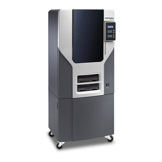
1 INTRODUCTION The Fortus 250mc system is designed with ultimate simplicity in mind. The system enables you to build parts quickly, even if you have never used a Fortus system before. The system models with ABSplus™ plastic, so modeled parts are strong and durable. ABSplus also ensures that you will be able to drill, tap, sand, and paint your creations. -
Page 9: Safety Precautions
SAFETY PRECAUTIONS The following precautions ensure the proper use of the system and prevent the system from being damaged. Follow these precautions at all times. • Ensure the system will be installed on a stable flat surface capable of holding 159 kg (350 lbs). •... - Page 10 Recycle: Use proper recycling techniques for materials and packaging. ESD: Use standard electrostatic discharge (ESD) precautions when working on or near electrical components.
-
Page 11: Overview
The Fortus 250mc system consists of two primary components — the Fortus 250mc system and Insight. Insight is the preprocessing software that runs on a Windows Vista or Windows 7 platform. - Page 12 Figure 2-1: Front view Extrusion Head Display Panel Extrusion Tips Tip Cleaning Assembly Guide Rods Purge Container Lead Screw Z stage platen Modeling Base Modeling Base Retainers (2) Model Material Cartridge Power Switch Support Material Cartridge...
- Page 13 Figure 2-2: Rear view Fan Cover UPS Connection Main Circuit Breaker Diagnostic Hookup Power Cord Adapter Network Cable Connection...
- Page 14 Figure 2-3: Material cartridge Figure 2-4: Modeling base Modeling base Caution: DO NOT reuse modeling bases. If a modeling base is reused, calibration errors, poor part quality, and loss of extrusion may occur. Additional modeling bases are available from your reseller.
- Page 15 Crossover Cable (Orange) 13 Needle Nose Pliers Network Cable (Blue) 14 Cutters Model and support tips 15 Fortus 250mc System Software CD Tip shield (8) 16 Fortus 250mc User Guide CD Tip Wipe assembly (4) 17 Insight CD 10x Magnifier Loupe...
-
Page 16: Setup
3 SETUP UNPACKING This section describes the recommended procedures for unpacking and preparing the system for its first use. UNPACK THE SYSTEM Warning: The system weighs approximately 148 kg (326 lbs). Use proper moving and lifting techniques when positioning the unit. For your convenience, there are forklift pads built into the bottom of the unit. - Page 17 Remove the foam tubes that isolate the extrusion head from the frame, see Figure 3-1. Figure 3-1: Foam tubes isolating the extrusion head from the XY-axis frame Extrusion Head Foam tubes (4) After unpacking, inspect the system and report any shipping damage to the carrier.
-
Page 18: Installing Forklift Access Covers
INSTALLING FORKLIFT ACCESS COVERS The forklift access covers can be placed over the forklift channels after the system is placed in its final location. The covers are press-fit in the front and held in place with one screw in the rear. Align the left and right side fork lift covers with the forklift channel and slide the tabs into the slots. -
Page 19: Networking The System
NETWORKING THE SYSTEM There are two methods of connecting your system to your workstation, over a network or with a direct connection to your workstation. CONNECTING THROUGH A NETWORK Locate the network cable (blue) from the startup kit. Connect the network cable between the system and the network hub. See Figure 3-4. -
Page 20: Connecting Directly To A Workstation
CONNECTING DIRECTLY TO A WORKSTATION Locate the crossover cable (orange) from the startup kit. Connect the crossover cable between the system and the network port on your workstation. See Figure 3-5. Establish communication, see “Establishing communication on a static network” on page 18 Figure 3-5: Connecting directly to a workstation... -
Page 21: Power Connections
POWER CONNECTIONS This section discusses the procedure for preparing all power connections for the system. Caution: Before connecting power to the system, make sure that the circuit breaker is in the off (down) position. It is located at the rear of the system, next to the power cord attachment point. -
Page 22: Powering On
POWERING ON Warning: The build chamber and extrusion-head tip get very hot! The chamber and head tip reach temperatures of approximately 75°C (167°F) and 280°C (536°F) respectively. Personal injury can occur if proper techniques and safety materials are not used. Use the leather safety gloves provided in the Startup Kit when working inside the system. -
Page 23: Installing Software
Figure 3-8: Location of power switch INSTALLING SOFTWARE There are three software programs that work with the system: Insight, the processing software installed on your workstation, processes the STL files for building. Control Center, the communication software installed on the workstation, communicates with the system. -
Page 24: Establishing Network Communication With The System
ESTABLISHING NETWORK COMMUNICATION WITH THE SYSTEM You will need to establish network communication between your workstation and system before you can send files to be built. How you establish this communication with an IP address is dependent upon how your network and workstation are configured. -
Page 25: Establishing Communication On A Static Network
ESTABLISHING COMMUNICATION ON A STATIC NETWORK If you are using a static network or connecting the system directly to a workstation, you will need to enter the static IP address information into the workstation and the system. If you are using a static network and your computer already has network access, see “Setting the static network on system”... - Page 26 SETTING THE STATIC NETWORK ON SYSTEM Obtain your static network address from your Network Administrator. From Idle (or Ready to Build), press Maintenance on the display panel. The display will show Maintenance and the software version. Press System. Press Set Network. The top window displays: Network Admin - Static IP Address; UDN. Press Static IP to display default settings.
-
Page 27: Installing System Software On System
Enter the IP Address for your system in the appropriate field. It will be the same address as entered in step 6. Select your system type from the drop down list, Fortus 250mc. Note: If you only have one system connected, it will be the only system in the list. -
Page 28: Insert Modeling Base
INSERT MODELING BASE Make sure retainers are turned ‘down’ - so as not to interfere with the modeling base installation. Set the modeling base on the Z Stage Platen aligning the tabs on the modeling base with the slots on the metal tray. Slide the modeling base toward the back of the unit until its front edge (with the handle) is flush with the front edge of the tray, see Figure 3-9. -
Page 29: Operation
4 OPERATION DISPLAY PANEL AND KEYPAD The main User Interface to the system is the Display Panel and Keypad, see Figure 4-1. Figure 4-1: Display panel and keypad Display Panel Keypad buttons Context-sensitive displays The display panel and keypad are very easy to use, consisting of a larger multiple-line LCD display on top, and four single-line context-sensitive displays, each with one button (or key) below. -
Page 30: System Software Overview
SYSTEM SOFTWARE OVERVIEW • Idle: If there is no part being built and no part in the build queue, the display will show that the system is Idle. • Wait for Part or Start Part: If the system is in Idle and the build queue is empty, you can set it to wait for a part. -
Page 31: Control Center Overview
CONTROL CENTER OVERVIEW • Pack tab: This section shows you which parts are in the pack for printing. You can add parts, arrange the parts for a better fit or clear the pack from this section. • Queue tab: This section shows you the amount of material remaining (both model and support) as well as which parts are in the Build Queue. -
Page 32: Processing Your Stl File For Printing
PROCESSING YOUR STL FILE FOR PRINTING OPENING YOUR STL FILE WITH INSIGHT Create an STL file using your CAD software. Refer to your CAD software help section for more information about converting your CAD drawings into STL files. Open the Insight software. From the File menu select Open STL... -
Page 33: Selecting Support Style
SELECTING SUPPORT STYLE Support material is used to support the model during the build process. It is removed when the part is complete. Support styles will affect the support strength and build time of the print. SMART support is the default support setting. -
Page 34: Selecting The Orientation Of Your Stl File
SELECTING THE ORIENTATION OF YOUR STL FILE How a part is oriented in the preview window will determine how the part is oriented when it prints. Orientation impacts build speed, part strength, surface finish and material consumption. Orientation can also affect the ability of Insight to repair any problems with the STL file. -
Page 35: Processing Your Stl File
PROCESSING YOUR STL FILE To finish preprocessing the STL file with the default presets: Click on the (Finish) button to finish all remaining preprocessing for the STL file and create the CMB file. Note: Clicking on the Finish button will process the STL file with the default processing presets. -
Page 36: Building A Part
BUILDING A PART If a part has not been sent to your system for building, the build queue will be empty. If the build queue is empty the display panel will show Idle or Ready to build. Choose whether or not you want to start a build from a remote location or from the display panel at the system. STARTING A BUILD FROM A REMOTE LOCATION To start a build from a remote location, the system must first be prepared to start the build. -
Page 37: Loading Material
LOADING MATERIAL Material cartridges are factory packaged in a box and an anti-static, moisture-proof bag to preserve shelf life. It is recommended to keep the material in the sealed bag until it is going to be loaded into the printer to keep the material from absorbing moisture. - Page 38 Figure 4-5: Direction to move cartridge roller Pull material out of cartridge to expose about 12 inches of material. You should easily be able to pull out the material. Note: The above step makes sure that the material will feed freely from the spool.
-
Page 39: Unloading Material
UNLOADING MATERIAL The model and support material cartridges may be replaced separately or at the same time. In idle-, load-, or build-related modes, the panel displays the percentage of material remaining in the cartridges. If the system will be operating unattended for a long period, and the material level is getting low, you may want to replace the cartridges before starting a new part. -
Page 40: Building A Test Part
BUILDING A TEST PART Factory test parts have been preloaded into your system. To familiarize yourself with the system, it is recommended that you build one of the test parts before attempting to build one of your own files. Once the system has warmed up, material has been loaded, and a modeling base is in place, you can send a test part to the system. -
Page 41: Pausing Build
PAUSING BUILD While building a part, you may want to pause the operation - e.g., to allow for replacement of a material cartridge. To pause the build operation at any time, press Pause. Note: When the build process is paused, the system completes the current tool path before pausing. -
Page 42: Canceling A Job
CANCELING A JOB You can cancel a job at any time while the part is building. CANCEL A JOB Press Pause. Once the system stops building, press Cancel Build. The panel displays Are you Sure? Press Yes. The panel displays Build Stopped followed by the part name. The panel prompts you to remove the part and replace the modeling base. -
Page 43: Removing A Completed Part
Warning: When removing soluble supports by hand, wear leather gloves and safety glasses. Fortus 250mc uses soluble supports - designed to allow you to simply wash away the support material in a water-based solution. Your part is left smooth and clean with the fine details intact. The soluble support material can be removed by hand with relative ease, but is designed to be dissolved off of your parts for hands-free part finishing. -
Page 44: Maintenance
Open the Control Center application and select the Services tab and then click Check for System Updates. The Stratasys Update Manager window will appear. The application will check to see if the Controller software is current. Follow screen prompts to update the Controller software. -
Page 45: Cd Method (Alternate Method)
CD METHOD (ALTERNATE METHOD) This method is for customers who do not have web access. The Controller Software Update CD containing the updated .upg file and must be obtained from Stratasys. Inc. Insert the Controller Software Update CD into the workstation computer. -
Page 46: Preventive Maintenance
PREVENTIVE MAINTENANCE Follow the simple procedures within this chapter to ensure continued proper operation of the system. DAILY INSPECT THE TIP WIPE ASSEMBLY After each build you should inspect the tip wipe assembly to make sure there is no material build up or wear. If there is material build up or wear, clean the tip wipe assembly. - Page 47 EMPTY THE PURGE CONTAINER The plastic purge container is attached to the right side of the modeling envelope rear wall, see Figure 5-2. Note: A full purge container may impact part quality. Remove the purge container by grasping it and pushing it upward to release it from its three mounts.
-
Page 48: 500 Hour Maintenance
500 HOUR MAINTENANCE Preventive Maintenance Alerts will be displayed on the workstation at the 500 hour time interval as a reminder to perform preventive maintenance. See Figure 5-3. Figure 5-3: Preventive Maintenance Alert CLEAN FAN FILTER To clean the fan filter: Locate the lower fan on the rear panel of the system and remove the plastic frame (snaps on and off) that secures the fan filter. -
Page 49: Replace The Tip Wipe Assembly
REPLACE THE TIP WIPE ASSEMBLY Note: The tip wipe assembly should be replaced after 500 hours, prior to performing Tip Cleaning Maintenance. Completely power down the system. See “Powering Off” on page Move the Toggle Head to the left of the machine in order to gain access to the tip wipe assembly, Figure 5-4. -
Page 50: Tip Shield Replacement
TIP SHIELD REPLACEMENT Tip shields can become worn or damaged over time. This can have a negative impact on the surface finish and detail of models. Figure 5-7: Tip shield damage New shield Worn shield Enter Head Maintenance. From the display panel press Maintenance. Press Machine. - Page 51 Position the blade of a small screwdriver between the tip shield and tip plate. Use the blade of the small screwdriver to separate the tip shield from the tip plate. See Figure 5-9. Figure 5-9: Tip shield removal Insert small standard screwdriver Tip plate to pry tip shields from tips.
- Page 52 Figure 5-11: Tip shield installation Figure 5-12: Tip shield placement Tip shield seated correctly Tip shield NOT seated correctly Replace head cover. Note: If the head cover is not replaced the system may not function properly. Exit Maintenance, press Done until back at Idle.
-
Page 53: 2000 Hour Maintenance
2000 HOUR MAINTENANCE Preventive Maintenance Alerts will be displayed on the workstation at the 2000 hour time interval as a reminder to perform preventive maintenance. See Figure 5-13. Figure 5-13: Preventive Maintenance Alert LIQUEFIER TIP REPLACEMENT Replace tips at approximately 2000 hours - depending upon operating conditions. Tips can also be damaged by improper care while performing maintenance in the area around the tips. - Page 54 REMOVING TIPS You will need to make sure the system is powered ON before replacing the extrusion tip. From the display panel press Maintenance. Press Machine. Press Tip. Press Replace. The system will display Material Unload - Unloading Model. When unload is complete, display will prompt to remove the material cartridges. You can now open the system door and replace the tips - or you can Cancel the tip replacement procedure.
- Page 55 Repeat for second tip if necessary. INSTALLING TIPS You must identify the correct replacement tip. The Fortus 250mc uses two tip types. You must make sure a SUPPORT tip is used on the LEFT side of the head assembly. A MODEL tip must...
- Page 56 With gloved hand, insert the new tip into the heater block. Use needle nose pliers to grasp the stainless steel shield of the tip. Pull the tip shield toward you, then lift up to install the tip. Push the tip toward the back of the system once it is all the way up against the heater block. Verify the tip is fully inserted into the heater block and that the stainless steel shield is aligned, Figure 5-18.
- Page 57 Figure 5-19: Tip shield installation Figure 5-20: Tip shield placement Tip shield seated correctly Tip shield NOTseated correctly Replace head cover. Note: If the head cover is not replaced the system may not function properly. Close the system door. The system will display Tip Maintenance - Tips Replaced? - select Yes to begin material load. The system will display Maintenance - Add/Remove (flashing).
- Page 58 After Material Loading is complete the system will display Calibration - Install Modeling Base And Build Cal Part. Caution: Make sure a NEW, UNUSED modeling base is installed before starting calibration. Calibration results will be incorrect if a previously used modeling base is installed.
-
Page 59: As Needed Maintenance
Select Done after you have input the X and Y offsets. The system will return to Maintenance. Run the XY calibration a second time to be sure the values changed the offset properly. When finished, press Done until back at Idle. AS NEEDED MAINTENANCE The following maintenance items have no routine schedule but should be tended to as needed. -
Page 60: Troubleshooting
6 TROUBLESHOOTING TROUBLESHOOTING CHECKLIST Problem or error message Solution 1. Verify power cord is securely plugged in. No power 2. Verify that the circuit breaker (at rear of system) and the power switch (on front panel of system) are both in the ON position. 3. -
Page 61: Fault Determination Codes
Problem or error message Solution “Cycling power” on 1. Remove cartridge and cycle power, see Display Panel displays page 55 ; reload cartridge. Could Not Read Cartridge 2. Try a different cartridge. 1. Retry with same cartridge. Display Panel displays Load Failed 2. -
Page 62: Cycling Power
CYCLING POWER Turn the power switch to the OFF position. The display will show Shutting Down. After the system has cooled down enough to shut down, the display will go blank. When the display is blank and the system has shut down, turn the circuit breaker to the OFF position. -
Page 63: Clogged Tip
If material did NOT flow from the support tip, see “Recovering from loss of extrusion” on page If material steadily flowed from the support tip, the support tip is functioning properly. Return the system to the Maintenance state - Press Done. Display will ask Which Materials Loaded? Press Both. -
Page 64: Material Jam
Press Blower Off, this will turn the head cooling fan off for 10 seconds, allowing the tip to heat up beyond operating temperature. If material starts to extrude the tip is no longer clogged. If material does not extrude see “Recovering from loss of extrusion”... - Page 65 Figure 6-2: Remove the head cover Press tabs in to Head Cover remove head cover Inspect tip inlets for material build up see Figure 6-3. If there is excess material build up see “Recovering from loss of extrusion” on page 59.
-
Page 66: Recovering From Loss Of Extrusion
Reinstall the head cover. Note: If the head cover is not replaced the system may not function properly. Press Done. Display will ask Which Materials Loaded? Press Both. Press Done until back to Pause screen. Press Resume to continue building the part. RECOVERING FROM LOSS OF EXTRUSION Note: It is recommended that you read and understand this entire procedure before performing any of the work. - Page 67 Place the toggle bar in neutral position (bar will extend equally from both sides of head). This can be done manually - push on the extended bar end. See Figure 6-5. Figure 6-5: Head Components Toggle spring Drive wheel Support side idler wheel Model side idler wheel...
- Page 68 Remove any excess material found around the head area. Note: Material fed to the tip can sometimes jam causing a build-up of material under the head cover. Clean out as much of the material as possible using needle nose pliers, a probe, or equivalent tool.
- Page 69 iii. Move idler wheel assembly by pushing with ⁄ ” T-Handle Allen wrench against spring tension. Insert a ⁄ ” Figure 6-8 T-handled Allen wrench (from startup kit) into the fixture hole. See Figure 6-8: Holding access space open - model side shown Insert 1/8 inch T-Handle into fixture hole.
- Page 70 Repeat for the opposite side as needed. Replace the head cover. Note: If the head cover is not replaced the system may not function properly. Press Done on the display panel. Display will ask Which Materials Loaded? Press Model if only model material is loaded, press Support if only support material is loaded or press Both if both model and support material are still loaded.
-
Page 71: Support
7 SUPPORT CUSTOMER SUPPORT Contact your local reseller for customer support. When contacting your reseller please provide the following: Your name. • • Your telephone number. • System model. System serial number. • • System software build number. • Insight and Control Center version number. •... -
Page 72: Recycling
8 RECYCLING Visit http://www.stratasys.com/recycle for recycling information on material cartridges. RECYCLING CODES System Component Materials Recycling Code Modeling bases All packaging materials can be recycled per your local recycling guidelines. -
Page 73: Printer Specifications
153 mm (6 in) minimum space around printer for air circulation. Network Connection Ethernet 10/100 Base T within 4m (14 ft). WORKSTATION SPECIFICATIONS For details, see the Insight Workstation Requirements document available from the Stratasys website. POWER SPECIFICATIONS Source (nominal) 100–240VAC ~ 15 - 7A 50/60Hz 1200W Do not use an extension cord or a power strip. -
Page 74: Supplemental Information
10 SUPPLEMENTAL INFORMATION UNINTERRUPTIBLE POWER SUPPLY (UPS) USE AND INSTALLATION The intent of the Uninterruptible Power Supply (UPS) shutdown feature on Fortus systems is to prevent required maintenance and/or system damage by safely shutting the system down in the event of an uncontrolled loss of power. -
Page 75: Parts List - Cable, Ups To Fortus System
Figure 10-1: Wired-And configuration PARTS LIST – CABLE, UPS TO FORTUS SYSTEM Item Nomenclature / Description Material Specification Conn, Hsg, Plug, 9Pos AMP - 205204-9 Pin, Male, 24-20 AWG AMP - 1-66506-0 Shell, Size 1, 9-Pin w/Grommets AMP - 748677-1 Jackscrew Pair 4-40, Knurled AMP - 747784-3 XX.x... - Page 76 Figure 10-2: UPS Cable Diagram...
-
Page 77: Declaration Of Conformity
Rules. Caution: Pursuant to Part 15.21 of the FCC Rules, any changes or modifications to this equipment not expressly approved by Stratasys, ltd. may cause harmful interference and void the FCC authorization to operate this equipment. Note: This equipment has been tested and found to comply with the limits for a Class A digital device, pursuant to Part 15 of the FCC Rules. -
Page 78: Canada Electromagnetic Compatibility (Emc)
Radio Interference Regulations of the Canadian Department of Communications. MSDS (MATERIAL SAFETY DATA SHEET) You can obtain current Material Safety Data Sheets for the material used in the printer by visiting: www.stratasys.com/materials/material-safety-data-sheets. DISPOSAL OF WASTE EQUIPMENT BY USERS IN PRIVATE HOUSEHOLDS IN THE EUROPEAN UNION This symbol on the product or on its packaging indicates that this product must not be disposed of with your other household waste. - Page 79 11 GLOSSARY | D | E | F | | H | | K | | N | | R | | W | | Y | Z Build Envelope The area within the modeler where the part is built. The part must be small enough to fit inside the build envelope.
- Page 80 The set of data sent to a Modeler. Layer A single, horizontal, cross-sectional cut of a 3D model. The height of each layer is equal to the Layer resolution. Each slice will have support (if necessary) and model toolpath information for the modeler. (Syn: Slice) Layer resolution The thickness (magnitude) of each slice created by Insight.
- Page 81 Queue A lineup of models waiting to be built. When a job command is downloaded to a system, it is added as an entry to the system's queue. By default, the entry will wait until all entries submitted before it have been completed. A system administrator can edit the queue in the Queue Tab.
- Page 82 Unit of Measure The definition to be used in determining the size of a part (inches or millimeters). View The 'camera angle' and 'zoom' that you choose for previewing a part. View does not impact building.
- Page 83 Customers, resellers, and Stratasys employees are encouraged to send comments about our documentation and training to c-support@stratasys.com. We greatly value your comments, review all of them, and use them to improve subsequent releases of the documentation. In your email message please include the document title, part number (located on the front cover), and page number.
Need help?
Do you have a question about the Fortus 250mc and is the answer not in the manual?
Questions and answers