Table of Contents
Advertisement
Quick Links
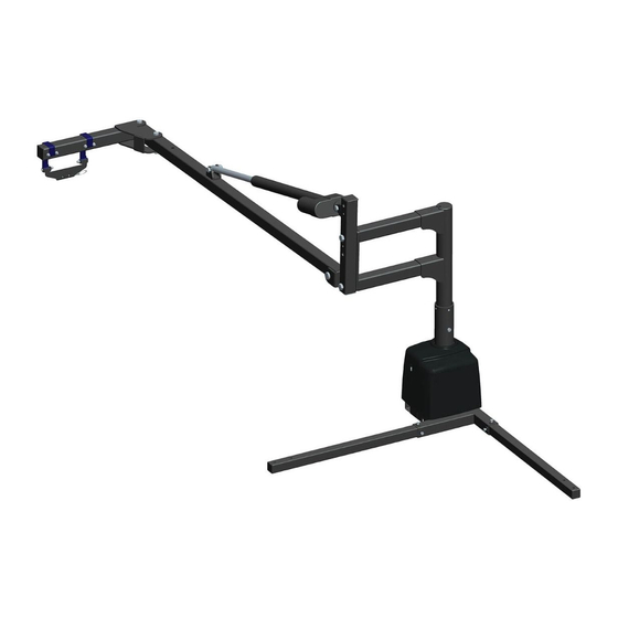
Truck Lifts
AL815CC, AL825, AL825CC, AL835
Installation & Owner's Manual
Standard Cab Models:
AL825
Standard Cab
Truck Lift -Performance
Capacity: 210 lbs
AL835
Standard Cab
Truck Lift - Heavy Duty
Capacity: 350 lbs
Read and understand this manual thoroughly before
attempting to install or operate the lift. If you have any
questions, please contact your Authorized Harmar Dealer or
Harmar's Technical Service Department.
P 800-833-0478 | F 866-234-5680 | tech@harmar.com
Available for both driver-side
and passenger-side installation
www.harmar.com | 800-833-0478
Crew Cab Models
Truck Lift - Performance
Dealer Name & Contact Information:
Serial # of Your Lift:
Install Date:
AL815CC
Crew Cab
Capacity: 135 lbs
AL825CC
Crew Cab
Truck Lift -Heavy Duty
Capacity: 225 lbs
Advertisement
Table of Contents

Subscribe to Our Youtube Channel
Related Manuals for Harmar Mobility AL815CC


Summary of Contents for Harmar Mobility AL815CC
- Page 1 Truck Lifts AL815CC, AL825, AL825CC, AL835 www.harmar.com | 800-833-0478 Installation & Owner’s Manual Standard Cab Models: Crew Cab Models AL815CC AL825 Crew Cab Standard Cab Truck Lift - Performance Truck Lift -Performance Capacity: 135 lbs Capacity: 210 lbs Available for both driver-side...
-
Page 2: Table Of Contents
AL815CC . . . . . . . . . . . . . . . . . . . . -
Page 3: Section 1: Owner
[Figure 3-3] The Docking Device may also be left permanently attached to the lifting arm on the pick-up truck lift. [Figure 3-4] [Figure 3-4] AL815CC, AL825, AL825CC, AL835 Hybrid Installation & Owner's Manual 2017 TEC00037 2016FEB20 P/N: 630-00053 Rev A... - Page 4 Operating Your Lift SECTION 1 : OWNER Types of Docking Devices The Docking Devices shown are two of the most [Figure 4-1] common and can lift most power chairs and scooters.However, many other devices are available. [Figures 4-1 thru 4-5] Please consult the instructions provided with your Docking Device or contact our technical service department to find the specific device that will work...
-
Page 5: Loading/Securing
Docking Device. [Figure 5-3] Be sure no people, children or [Figure 5-3] animals are under the payload before lowering WARNING AL815CC, AL825, AL825CC, AL835 Hybrid Installation & Owner's Manual 2017 TEC00037 2016FEB20 P/N: 630-00053 Rev A... - Page 6 Operating Your Lift SECTION 1 : OWNER Some applications may require the seat back be Attach the Docking Device specific to your folded. [Figure 6-1] application. [Figure 6-2] [Figure 6-1] [Figure 6-2] Pull the quick pin from the lifting hook. Align the docking device and lifting hook as indicated.
-
Page 7: Safety & Maintenance
Chair/Scooter on Lifting Arm Must Clear Truck Bed Wall CAUTION Before lowering, verify the lift with its chair/scooter has completely rotated and will not collide with the truck. AL815CC, AL825, AL825CC, AL835 Hybrid Installation & Owner's Manual 2017 TEC00037 2016FEB20 P/N: 630-00053 Rev A... - Page 8 Operating Your Lift SECTION 1 : OWNER When the chair/scooter reaches the desired position, lower the chair/scooter by pressing the ‘DOWN’ button on the remote control. [Figure 8-1] [Figure 8-1] Stop lowering when about ¾ of the chair/scooter’s weight is on the floor. The best transportation position for the chair/scooter will be with the lifting arm holding the chair in position, as well as most of the chair/scooter resting on the floor of the truck...
- Page 9 / installer under the scooter or power chair as it is being loaded and unloaded. to have one installed. AL815CC, AL825, AL825CC, AL835 Hybrid Installation & Owner's Manual 2017 TEC00037 2016FEB20 P/N: 630-00053 Rev A...
-
Page 10: Section 2: Installer
Preparation SECTION 2 : INSTALLER Professional Installation Recommended NOTE: The following section is designed for the professional installer. We strongly recommend that a certified dealer install the lift and instruct the user on correct operation as well as establish a safety and maintenance schedule. -
Page 11: Unpacking The Lift
EXTENSION POWER BASE BASE ADAPTER ASSEMBLY ( DRIVER's SIDE or PASSENGER's SIDE ) VERTICAL POST HARDWARE CHECK LIST / PACK INSPECTION SHEET LEG EXTENSIONS AL815CC, AL825, AL825CC, AL835 Hybrid Installation & Owner's Manual 2017 TEC00037 2016FEB20 P/N: 630-00053 Rev A... -
Page 12: Installation Overview
Preparation SECTION 2 : INSTALLER Installation Overview Never attempt to pick up the lift from the box, ground or on/off a vehicle alone. WARNING Two people should work together to place this lift inside a vehicle. If only one person is available, please follow the short disassembly procedure below. -
Page 13: Installation
Attach the black wire to the negative terminal on the battery. [Figure 13-2] SIDE MOUNT TOP MOUNT Do NOT attach the red wire until the very end of installation. [Figure 13-2] AL815CC, AL825, AL825CC, AL835 Hybrid Installation & Owner's Manual 2017 TEC00037 2016FEB20 P/N: 630-00053 Rev A... - Page 14 Wiring the Vehicle SECTION 2 : INSTALLER 2. Run the vehicle harness under and, when Coil Excess Wire. possible, through the vehicle back to the rear Do NOT cut or shorten the harness cargo area/trunk. CAUTION Run the wire under and through the vehicle whenever possible, gaining entry into the vehicle through the firewall Do NOT run wiring where it can be snagged by...
- Page 15 It is always best to test both current and voltage, or run the motor with known good shop battery or power source when troubleshooting. AL815CC, AL825, AL825CC, AL835 Hybrid Installation & Owner's Manual 2017 TEC00037 2016FEB20...
- Page 16 Installation SECTION 2 : INSTALLER Base Installation Driver's Side Base 1. Place base in corner of truck bed as shown. Attempt to position as close to the corner as possible. Leave at least 1” around on all sides. [Figure 16-1] Passenger's Side Base ( sold as option ) [Figure 16-1]...
- Page 17 Once again, be sure the larger hole will avoid vehicle’s gas tank, spare tire, suspension components, etc. Finish drilling all three holes with a 3/8” or slightly [Figure 17-3] larger drill bit. AL815CC, AL825, AL825CC, AL835 Hybrid Installation & Owner's Manual 2017 TEC00037 2016FEB20 P/N: 630-00053 Rev A...
- Page 18 Installation SECTION 2 : INSTALLER Base Installation (con’t) 3/8-16 Hex Nut 4. Secure base to the truck bed using hardware 3/8 Split indicated below. Tighten all hardware (except Loc Washer temporary hex nut) to approx. 30 ft. lbs. 3/8-16 3/8-16 Hex Nut All-Thread Temporary...
- Page 19 Anchor 3/8 Split Bracket Loc Washer Installation Installation Washer Washer 3/8 Split Loc Washer 3/8-16 3/8-16 Hex nut Hex nut Figure 19-2 Figure 19-4 AL815CC, AL825, AL825CC, AL835 Hybrid Installation & Owner's Manual 2017 TEC00037 2016FEB20 P/N: 630-00053 Rev A...
-
Page 20: Post Installation
Installation SECTION 2 : INSTALLER Post Installation The average installation will require approximately 180 degrees of rotation as shown. [Figures 20-1 & 20-2] Figure 20-1 Figure 20-2 3/8-16 x 3-1/2"L Loosen Hex Head Cap Screw Set Screws (x4) 1. Loosen set screws and insert vertical post. - Page 21 [Figure 21-2] You may also need to flip the rotation cut-off switches to properly stop the motor. [Figure21-3] Figure 21-2 Figure 21-3 AL815CC, AL825, AL825CC, AL835 Hybrid Installation & Owner's Manual 2017 TEC00037 2016FEB20 P/N: 630-00053 Rev A...
- Page 22 Adjustments SECTION 2 : INSTALLER Installing The Arms 1. Rotate the vertical post outside the truck. [Figure 22-1] Figure 22-1 2. Attach lifting Arm as indicated. Tighten bolts to at least 100 ft. lbs. [Figure 22-2] 5/8-11 x 3" 5/8"Split Hex Head Loc Washer Cap Screw...
- Page 23 Never wrap strap over edge of strap keeper. WARNING NOTE: Bolt must always be inserted through the top. If inserted from the bottom, the nut will interfere with the activator. AL815CC, AL825, AL825CC, AL835 Hybrid Installation & Owner's Manual 2017 TEC00037 2016FEB20 P/N: 630-00053 Rev A...
-
Page 24: Installing The Control Box
Installation SECTION 2 : INSTALLER Installing The Control Box A small black switch with 10 feet of coiled wire is included in the Truck Lift hardware kit. This allows the hand control to extend into the cab of the truck. One end of the coiled wire has no connector, allowing entry from the lift in the truck bed to the truck cab using the smallest opening possible. - Page 25 Tighten each wire down after insertion. [Figure 25-3] Test each wire by pulling it moderately to make sure that it is secure in the contact block. Figure 25-3 AL815CC, AL825, AL825CC, AL835 Hybrid Installation & Owner's Manual 2017 TEC00037 2016FEB20 P/N: 630-00053 Rev A...
- Page 26 Installation SECTION 2 : INSTALLER 6. Carefully fold the enclosure lid back over enclosure to avoid trapping any wires. Use supplied screws (x2) to fasten the lid to the bottom enclosure. [Figure 26-1] Figure 26-1 7. If customer prefers, fasten enclosure to chosen location using self-drilling screws provided.
-
Page 27: Troubleshooting
D I N G REMOVED FOR CLARITY MOTOR DEAD TEST FIRST THEN S H O P S H O CONNECT POWER EXAGGERATED TEAR OR CHAFF AL815CC, AL825, AL825CC, AL835 Hybrid Installation & Owner's Manual 2017 TEC00037 2016FEB20 P/N: 630-00053 Rev A... - Page 28 Troubleshooting SECTION 2 : INSTALLER PROBLEM Lift does not operate or lift operates slowly or intermittently CAUSE Bad electrical connection(s) / Circuit breaker SOLUTION Figure 28-1 Check / clean all connections that might be loose or dirty. This is the #1 cause of a poorly performing lift.
- Page 29 PROBLEM Lifting arm is difficult to rotate. CAUSE Dry / dirty bushings SOLUTION Clean and lubricate bushings in base with white/lithium grease or equivalent. AL815CC, AL825, AL825CC, AL835 Hybrid Installation & Owner's Manual 2017 TEC00037 2016FEB20 P/N: 630-00053 Rev A...
- Page 30 | www.harmar.com | 800-833-0478 | www.harmar.com | 800-833-0478...
-
Page 31: Al815Cc
(16) (67) 31 31 AL815CC, AL825, AL825CC, AL835 Hybrid Installation & Owner's Manual 2014 TEC00037 2016FEB20 P/N: 630-00053 Rev A... - Page 32 | www.harmar.com | 800-833-0478 | www.harmar.com | 800-833-0478...
- Page 33 33 33 AL815CC, AL825, AL825CC, AL835 Hybrid Installation & Owner's Manual 2014 TEC00037 2016FEB20 P/N: 630-00053 Rev A...
- Page 34 | www.harmar.com | 800-833-0478 | www.harmar.com | 800-833-0478...
- Page 35 35 35 AL815CC, AL825, AL825CC, AL835 Hybrid Installation & Owner's Manual 2014 TEC00037 2016FEB20 P/N: 630-00053 Rev A...
- Page 36 | www.harmar.com | 800-833-0478 | www.harmar.com | 800-833-0478...
- Page 37 37 37 AL815CC, AL825, AL825CC, AL835 Hybrid Installation & Owner's Manual 2014 TEC00037 2016FEB20 P/N: 630-00053 Rev A...
- Page 38 | www.harmar.com | 800-833-0478 | www.harmar.com | 800-833-0478...
- Page 39 39 39 AL815CC, AL825, AL825CC, AL835 Hybrid Installation & Owner's Manual 2014 TEC00037 2016FEB20 P/N: 630-00053 Rev A...
-
Page 40: Electrical
Electrical SECTION 2 : INSTALLER | www.harmar.com | 800-833-0478... - Page 41 Service Notes SECTION 2 : INSTALLER Service Description: Service Date: Performed By: Service Description: Service Date: Performed By: Service Description: Service Date: Performed By: AL815CC, AL825, AL825CC, AL835 Hybrid Installation & Owner's Manual 2017 TEC00037 2016FEB20 P/N: 630-00053 Rev A...
- Page 42 Service Notes SECTION 2 : INSTALLER Service Description: Service Date: Performed By: Service Description: Service Date: Performed By: Service Description: Service Date: Performed By: | www.harmar.com | 800-833-0478...
- Page 43 Florida 34234. You may also register online at www.harmar.com. Keep a copy of this form for your records. Harmar Mobility warrants its lift products against defects in material, mechanical and electrical components (parts), excluding labor cost, batteries, paint and covers, for a period of three (3) years from date of retail purchase, provided that the products have been installed, maintained and operated properly.
- Page 44 Truck Lifts AL815CC, AL825, AL825CC, AL835 www.harmar.com | 800-833-0478 Installation & Owner’s Manual 2075 47 th Street Sarasota, Florida 34234 © 2014 HARMAR MKT-IOM-AL815CC, 825, 825CC, 835 29Jun17 Part Number: 000-0000-00 Rev DWG...
Need help?
Do you have a question about the AL815CC and is the answer not in the manual?
Questions and answers