Table of Contents
Advertisement
Inside Lifts
Installation & Owner's Manual
Read and understand this manual thoroughly before attempting
to install or operate the lift. If you have any questions, please
contact your Authorized Harmar Dealer or Harmar's Technical
Service Department.
P 800-833-0478 | F 866-234-5680 | tech@harmar.com
TEC0091 2016JUN30
P/N: 630-00076-Rev A
www.harmar.com | 800-833-0478
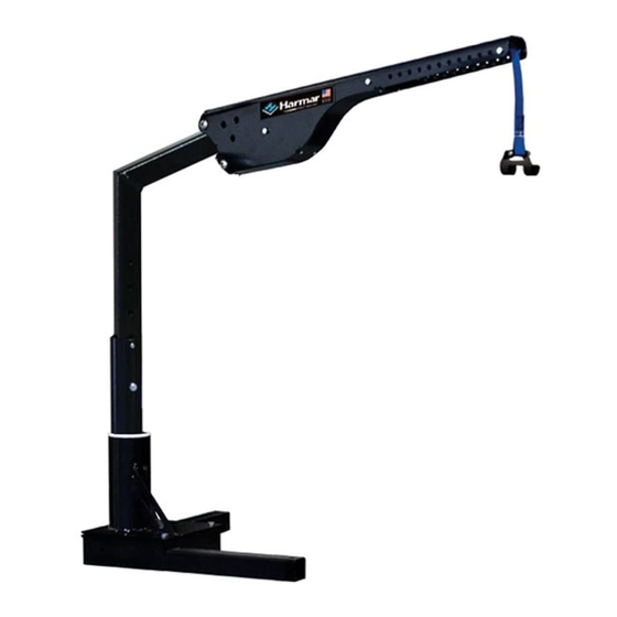
AL215 Axis I
Single Axis Inside Lift
Capacity: 250 lbs.
AL425 Axis II
2-Axis Inside Lift
Capacity: 400 lbs.
AL225 Axis II Lift
2-Axis Inside Lift
Capacity: 250 lbs.
AL435 Axis III
3-Axis Inside Lift
Capacity: 400 lbs.
AL435T Axis III
Truck Lift
Capacity: 400 lbs.
Dealer Name & Contact Information:
Serial # of Your Lift:
Advertisement
Table of Contents

Related Manuals for Harmar Mobility AL215 Axis I


Summary of Contents for Harmar Mobility AL215 Axis I
- Page 1 Inside Lifts www.harmar.com | 800-833-0478 Installation & Owner’s Manual AL215 Axis I Single Axis Inside Lift Capacity: 250 lbs. AL425 Axis II 2-Axis Inside Lift Capacity: 400 lbs. AL225 Axis II Lift 2-Axis Inside Lift Capacity: 250 lbs. AL435 Axis III 3-Axis Inside Lift Capacity: 400 lbs.
- Page 2 | www.harmar.com | 800-833-0478 © 2016 Harmar All Rights Reserved...
-
Page 3: Table Of Contents
CONTENTS SECTION 1 : OWNER OPERATING YOUR LIFT Using Your Lift .............. 2 Safety ................5 Maintenance ..............6 SECTION 2: INSTALLER TROUBLESHOOTING PREPARATION Problem, Cause, Solution .......... 26 Understanding the Manual ........7 EXPLODED VIEWS Installation Overview ..........8 AL215 ................ -
Page 4: Section 1 : Owner
OWNER OPERATING YOUR LIFT OPERATING YOUR LIFT 1. Park power chair or scooter ready to be picked-up along the side and parallel to the vehicle. [Figure 2-1] Always make sure the vehicle’s parking brake is firmly set. CAUTION! Figure 2-1 2. - Page 5 OWNER OPERATING YOUR LIFT Inspect lifting strap prior to use. Ensure the lifting strap is secure and that it points straight down. CAUTION! Failure to do so could result in the chair or scooter swinging, causing damage to operator, chair or vehicle. 4.
- Page 6 OWNER OPERATING YOUR LIFT When the lift is not being used, press the UP button to run the strap up and keep the hook from swinging. [Figures 4-1 thru 4-3] Tighten the strap only enough to prohibit the lift from rotating. Over-tightening may cause CAUTION! damage to the strap and/or lift.
-
Page 7: Safety
OWNER SAFETY SAFETY DO NOT operate this lift until your dealer has satisfactorily instructed WARNING you in its proper operation. ALWAYS CHECK CAUTION! THE LIFTING STRAP BEFORE EACH USE FOR DAMAGE OR WEAR Check regularly before use for any worn, loose, or damaged parts of the lift. -
Page 8: Maintenance
OWNER MAINTENANCE MAINTENANCE Your Inside Lift has been designed and engineered to be as trouble-free as possible. But as with any mechanical device, it requires regular care while owning and using it. ALWAYS check the lifting strap before use and while using the lift. If any wear or damage is noticed DO NOT USE THE LIFT! Contact the dealer or installer for repair. -
Page 9: Section 2: Installer
INSTALLER PREPARATION READ & UNDERSTAND THIS MANUAL PRIOR TO INSTALLATION OR OPERATION Having an overall understanding of the lift and proper installation techniques will help you save DO NOT attempt to pick up the time, energy and avoid possible injury. entire lift box from the ground;... -
Page 10: Installation Overview
INSTALLER PREPARATION INSTALLATION OVERVIEW 1. Trial Fit for Base Mounting Location To install the lift, you’ll most likely need to drill three holes in the vehicle’s floor. Do not drill until you simulate the lift’s range of motion inside the vehicle. Also simulate the object to be loaded. Determine an accurate location for the lift while maximizing the remaining cargo area. -
Page 11: Tools Required
INSTALLER PREPARATION TOOLS REQUIRED Installations may vary to some degree, but below are the basic tools to have on hand for an Inside Lift installation. WIRE CUTT TERS SAE SOCKETS SAE WRENCHES SAE ALLEN WRENCHES 7/16” 7/16” 5/32” 1/2” 1/2” 1/8”... -
Page 12: Unpacking The Lift
INSTALLER PREPARATION UNPACKING THE LIFT Check the box contents. Review each part against the packaging checklist to ensure that all parts have been included. If any parts are missing or damaged, immediately contact the dealer who sold the lift. Do not attempt to install or use a lift that has missing or damaged parts. -
Page 13: Installation
INSTALLER INSTALLATION WIRING THE VEHICLE Improper wiring is the #1 cause of problems in operating a vehicle lift. Follow the wiring 20 AMP SELF instructions carefully. RESETTING CIRCUIT BREAKER The vehicle wiring harness is located in the hardware CONNECTOR pack. The harness is manufactured to comply with TO BA TTERY SAE J1128 requirements. - Page 14 INSTALLER INSTALLATION If you want to run the harness under the vehicle, you will most likely need to drill a hole to get P r o t e the wire into the rear cargo area/trunk. Use the c t i v e t u b i n supplied 3/8 grommet in the hole to protect the wire.
-
Page 15: Trial Fit Procedure
INSTALLER INSTALLATION TRIAL FIT PROCEDURE The AL215, AL225, AL425, AL435 ,AL435T require a minimum of three holes to be drilled into the vehicle’s floor to secure the base. The positioning is vital to the lift's successful installation and operation. Figure 13-1 Figure 13-2 Before drilling any holes, ensure that the lift can be positioned to permit a full range of motion. -
Page 16: Base Installation: Flat Floor
INSTALLER INSTALLATION BASE INSTALLATION: FLAT FLOOR After you know the lift position from the trial fit procedure, you are ready to drill three 3/8” holes in the locations you marked. Telescoping Legs 23” (BA-00 shown) 1. Drill Pilot Holes 16” •... -
Page 17: Base Installation: 3Rd Row Folding Seats
INSTALLER INSTALLATION BASE INSTALLATION: ROW FOLDING SEATS 1" or 2” 1. Place vertical joiners on back wall of seating Fold up third VEHICLE’s THRESHOLD row seating CHOOSE well corner. [Figure 15-1] Use base as template for HOLE FOR CLOSEST TO WALL POSITION position. - Page 18 INSTALLER INSTALLATION EXPLODED VIEW OF ASSEMBLY FOR 3RD ROW INSTALLATION USE FOR SEAT ATTACHMENT POINT HHCS, 3/8-16 x 3-1/2”L J-HOOK NUT, NYLOC, 3/8-16 INSTALLATION WASHER NUT, NYLOC, 3/8-16 HHCS, 3/8-16 x 2-1/4”L HHCS, 1/4-28 x 1/2”L HHCS, 1/4-28 x 1/2”L NUT, NYLOC, 3/8-16 PhPnHd, 10-32 x 7/16”L...
-
Page 19: Base Installation: Truck Bed
INSTALLER INSTALLATION BASE INSTALLATION: TRUCK BED 1. Place base in corner of truck bed. Attempt to position as close to the corner as possible while leaving at least 1” clear around the base on all sides. [Figure 17-1] 2. Install leg extensions into base tubes and Passenger's Side Base Driver's Side Base Figure 17-1... - Page 20 INSTALLER INSTALLATION 4. Double-check hole positions for pilot holes. Mark the three hole locations. Use the base as a template, then remove base. Drill pilot holes down through truck bed in the marked locations. [Figure 18-1] 5. Climb under truck and inspect location of pilot holes.
- Page 21 INSTALLER INSTALLATION Figure 19-1 Inside Lifts - Installation & Owner’s Manual TEC0091 2016JUN30 P/N: 630-00076-Rev A...
-
Page 22: Lift Installation
INSTALLER INSTALLATION LIFT INSTALLATION 1. Raise the plastic base cover when the base has been fastened to the vehicle floor, and attach the lift to the base as shown. [Figure 20-1] 2. Be sure to compress all split lock washers when tightening all fasteners. - Page 23 INSTALLER INSTALLATION 4. Attach lifting arm as shown according to lift model. [Figure 21-1] 5. Plug in lifting motor. [Figure 21-2] AL-425 AL-435 Series AL-215 Attach lifting arm as shown to the right AL-225 according to lift model. Figure 21-1 Plug in lifting motor.
-
Page 24: Lift Adjustments
INSTALLER LIFT ADJUSTMENTS ADJUSTMENTS: HEIGHT AL425 / AL435 / AL435T • Remove bolt. • Loosen set screws (x4). [Figure 22-1] • Slide inner vertical post. • Replace bolt. • Tighten set screws/ (x4) [Figure 22-2] AL215 / AL225 • Remove bolt. •... -
Page 25: Pitch
INSTALLER LIFT ADJUSTMENTS ADJUSTMENTS : PITCH AL425 NOTE: The AL215 and AL225 are manufactured with a 6 degree pre-load so pitch adjustment is not • Remove bolt. necessary. • Rotate turnbuckle. • Replace bolt. [Figure 23-1] AL435 / AL435T • Loosen bolt. -
Page 26: Rotation
INSTALLER LIFT ADJUSTMENTS ADJUSTMENTS : ROTATION Do not set the limits to over rotate the arm. Damage may occur to the AL225 / AL425 / AL435 / AL 435T vehicle. The amount of allowable rotation is determined by CAUTION! the cams indicated below. Loosen set screw and rotate as required. -
Page 27: Docking Devices
INSTALLER DOCKING DEVICES DOCKING DEVICES The Docking Device is an interface between the lift and the power chair or scooter. Most power chairs and scooters can be lifted either by the center seat post or the four-post seat frame. Types of Docking Devices [Figures 25-1 and 25-2] These Docking Devices are two of the most common and can lift most power chairs and scooters. -
Page 28: Troubleshooting
INSTALLER TROUBLE SHOOTING TROUBLESHOOTING 20 A SELF RESTING The following procedures are reserved for the CIRCUIT BREAKER approved installer/dealer. They should not be attempted by anyone without proper knowledge of automotive electrical circuitry. Problem Lift does not operate or lift operates slowly or APPLY KNOWN GOOD POWER DIRECT TO MOTOR intermittently. - Page 29 INSTALLER TROUBLE SHOOTING NOTE: Be cautious when troubleshooting with a test These instruments will detect voltage, but may light or voltage meter. You may get a false indication not indicate a tear or poor connection in the as shown below. [Figure 27-1] It will indicate that a wiring.
-
Page 30: Exploded Views
INSTALLER EXPLODED VIEWS AL215 ASSEMBLY PARTS ASSEMBLY PARTS ASSEMBLY PARTS ASSEMBLY PARTS ITEM ITEM PART NO. DESCRIPTION PART NO. DESCRIPTION ITEM PART NO. DESCRIPTION ITEM PART NO. DESCRIPTION 200-3B01-A BASE COVER ASSEMBLY H10-2B01-A HARDWARE, KIT, MANUAL BASE MOUNTING 200-3B01-A BASE COVER ASSEMBLY H10-2B01-A HARDWARE, KIT, MANUAL BASE MOUNTING 240-ZB01-C... -
Page 31: Al225
INSTALLER EXPLODED VIEWS AL225 ASSEMBLY PARTS ASSEMBLY PARTS ITEM ITEM PART NO. DESCRIPTION PART NO. DESCRIPTION H425054 HARNESS (WIRES & SWITCHES NOT SHOWN) 200-3B03-A MOTOR HOUSING ASSEMBLY H425435 BASE COVER 240-ZB01-C SQUARE POST ASSEMBLY PARTS ASSEMBLY PARTS HHCS-0_37-16--3_50-Z HEX HEAD, 3/8-16 X 3.50, ZP 260-ZB01-A ARM ASSEMBLY ITEM... -
Page 32: Al425
INSTALLER EXPLODED VIEWS AL425 | www.harmar.com | 800-833-0478 © 2016 Harmar All Rights Reserved... -
Page 33: Al435
INSTALLER EXPLODED VIEWS AL435 Inside Lifts - Installation & Owner’s Manual TEC0091 2016JUN30 P/N: 630-00076-Rev A... -
Page 34: Al435T
INSTALLER EXPLODED VIEWS AL435 T | www.harmar.com | 800-833-0478 © 2016 Harmar All Rights Reserved... -
Page 35: Al215 & Al225 Arm
INSTALLER EXPLODED VIEWS AL215 & AL225 ARM ASSEMBLY PARTS ASSEMBLY PARTS ITEM PART NO. DESCRIPTION ITEM PART NO. DESCRIPTION ASSEMBLY PARTS ASSEMBLY PARTS 261-ZB01-C HOIST HOUSING ALA67997 LIFTING STRAP ITEM PART NO. DESCRIPTION ITEM PART NO. DESCRIPTION 570-ZB01-C HOIST HOUSING COVER BHCS-0_25-20--1_75-SS BUTTON HEAD, 1/4-20 x 1.75, SS 261-ZB01-C... -
Page 36: Al425 Arm
INSTALLER EXPLODED VIEWS AL425 ARM ASSEMBLY PARTS ASSEMBLY PARTS PART NO. DESCRIPTION PART NO. DESCRIPTION ITEM ITEM 214-2B03-P 26 TOOTH SPOOL BHCS-0_25-20--1_75-SS BUTTON HEAD, 1/4-20 x 1.75, SS 261-2B03-C HOIST HOUSING BHCS-0_50-13--0_75-Z BUTTON HEAD, 1/2-13 X 0.75, ZP ASSEMBLY PARTS ASSEMBLY PARTS ASSEMBLY PARTS ASSEMBLY PARTS... -
Page 37: Al435 Series Arm
INSTALLER EXPLODED VIEWS AL435 SERIES ARM ASSEMBLY PARTS ASSEMBLY PARTS PART NO. DESCRIPTION PART NO. DESCRIPTION ITEM ITEM - 0 9 _ 0 - - 5 2 - 0 2 _ 0 - 2 - 4 , 7 3 - 5 3 - 0 1 - 2 3 _ 0 -... -
Page 38: Al225 / Al425 / Al435 Series Base
INSTALLER EXPLODED VIEWS AL225, AL425 & AL SERIES BASE ASSEMBLY PARTS ASSEMBLY PARTS ITEM ITEM PART NO. DESCRIPTION PART NO. DESCRIPTION H425240 DOUBLE SPROCKET 19-35 , 8-35 201-ZB03-C MOTOR HOUSING H425241 DOUBLE SPROCKET 19-35 , 8-40 210-ZB03-C MOTOR HOUSING COVER H425255 LIMIT/MOTOR HOUSING SPACER 220-ZB03-C... -
Page 39: Electrical Diagram
INSTALLER ELECTRICAL AL-225 AL-425 e l l AL-215 Hand Vehicle's Harness Vehicle's Battery Controller Lift Wiring Hand Controller Vehicle Battery UP / DOWN 12 v Vehicle's Harness UP / DOWN Hand Controller MOTOR Vehicle's Battery 12 awg RED - Vehicle Battery 12 v F E D C B A F E D C B A... - Page 40 INSTALLER ELECTRICAL | www.harmar.com | 800-833-0478 © 2016 Harmar All Rights Reserved...
- Page 41 INSTALLER ELECTRICAL Inside Lifts - Installation & Owner’s Manual TEC0091 2016JUN30 P/N: 630-00076-Rev A...
- Page 42 INSTALLER NOTES | www.harmar.com | 800-833-0478 © 2016 Harmar All Rights Reserved...
-
Page 43: Warranty
Florida 34234. You may also register online at www.harmar.com. Keep a copy of this form for your records. Harmar Mobility warrants its lift products against defects in material, mechanical and electrical components (parts), excluding labor cost, batteries, paint and covers, for a period of three (3) years from date of retail purchase, provided that the products have been installed, maintained and operated properly. - Page 44 CONTENTS Inside Lifts www.harmar.com | 800-833-0478 Installation & Owner’s Manual 2075 47th Street Sarasota, Florida 34234 TEC0091 2016JUN30 P/N: 630-00076-Rev A | www.harmar.com | 800-833-0478 © 2016 Harmar All Rights Reserved...
Need help?
Do you have a question about the AL215 Axis I and is the answer not in the manual?
Questions and answers