
Subscribe to Our Youtube Channel
Related Manuals for Thermo Scientific QuantStudio 1


Summary of Contents for Thermo Scientific QuantStudio 1
- Page 1 ™ QuantStudio 1 Real-Time PCR System INSTALLATION, USE, AND MAINTENANCE Firmware v1.0.x Publication Number MAN0017853 Revision A.0 For Research Use Only. Not for use in diagnostic procedures.
- Page 2 Life Technologies Holdings Pte Ltd | Block 33 | Marsiling Industrial Estate Road 3 | #07-06, Singapore 739256 For descriptions of symbols on product labels or product documents, go to thermofisher.com/symbols-definition. The information in this guide is subject to change without notice. DISCLAIMER: TO THE EXTENT ALLOWED BY LAW, THERMO FISHER SCIENTIFIC INC.
-
Page 3: Table Of Contents
Contents About this guide ............8 ■... - Page 4 Contents Overview of Settings ............28 Manage instrument settings .
- Page 5 Contents View, pause, or stop a run ............46 View real-time data and plots on the instrument touchscreen .
- Page 6 Contents ■ CHAPTER 6 Maintain the instrument ....... . . 70 Backup or restore the instrument .
- Page 7 Contents ■ APPENDIX D Parts and materials ........91 Kits, consumables, accessories, and reagents .
-
Page 8: About This Guide
About this guide This guide provides information about installing, using, and maintaining the QuantStudio ™ 1 Real-Time PCR System. For information and instructions on ™ performing experiments on this system, refer to QuantStudio Design and Analysis Desktop Software User Guide (Pub. No. MAN0010408). QuantStudio 1 Real-Time PCR System Installation, Use, and Maintenance Guide ™... -
Page 9: Chapter 1 Product Information
Product information ■ Instrument hardware description ........9 ■... - Page 10 Chapter 1 Product information Instrument hardware description Instrument filters and supported dyes System dyes The instrument use a coupled three-color filter set that supports the dyes shown in the following table and figure. For more information about available spectral dye calibration kits, contact Support.
-
Page 11: Parts Of The Instrument
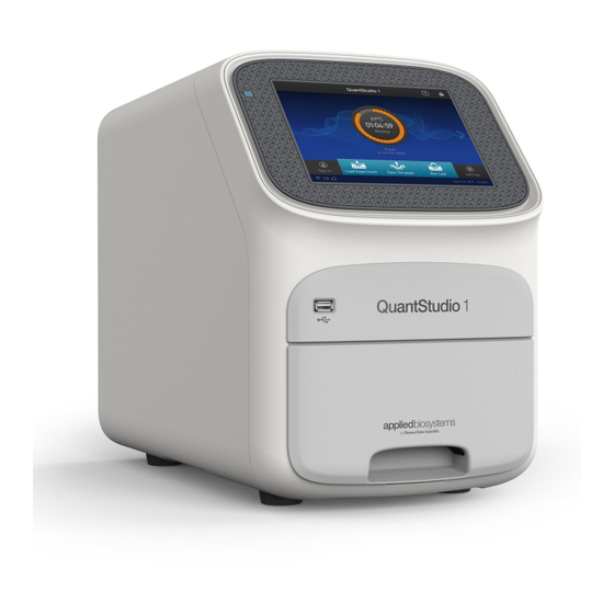
Chapter 1 Product information Instrument hardware description Parts of the instrument Touchscreen – Controls the instrument. USB port – For connection to an external network drive or external data storage device. Instrument drawer – Contains sample plate. The instrument includes three additional USB ports on the back of the instrument. Note: The instrument recognizes only one external storage device at a time for data transfer. -
Page 12: Parts Of The Home Screen
Chapter 1 Product information Instrument hardware description Parts of the home screen Avatar and Instrument name Settings button Help icon Buttons for accessing Experiment Template files (EDT) Drawer status Connectivity icons Status dial Sign In (or My Profile) button Current user name; instrument block type Table 2 Parts of the home screen Element of the Function... - Page 13 Chapter 1 Product information Instrument hardware description Element of the Function For more information, see... home screen • When the instrument is in use — Displays the Status dial — sample block temperature, the elapsed run time, and the run status. You can swipe the dial to the left or touch access real-time views of the run.
-
Page 14: Software Description
Chapter 1 Product information Software description Software description Instrument, The instrument and the software (desktop and cloud) include the features described in the following table. desktop, and cloud software Feature Instrument Desktop Cloud features Use as guest (no sign in) —... -
Page 15: Folders, Templates, Experiments, And Projects
Chapter 1 Product information Software description Folders, Term Definition Supported in templates, Folders in Load Location in which you can store templates (EDT Instrument experiments, and Experiment files) on the instrument: projects • My Instrument – Displayed if you are signed in •... -
Page 16: Third-Party Software
Chapter 1 Product information Supported options for instrument and computer connections Template and experiment Instrument Desktop Cloud components Plate Sample names Define and assign samples, targets or SNP assays, and tasks in the Quick Setup and Advanced Setup panes of the You cannot edit targets/SNP assays Plate tab. - Page 17 Chapter 1 Product information Supported options for instrument and computer connections Note: For detailed information about networking your instrument, see the ™ QuantStudio 1 Real-Time PCR System IT Checklist (Pub. No. MAN0018164). Direct configuration option • A computer provided by Thermo Fisher Scientific with the QuantStudio ™...
-
Page 18: Experiment Types
Chapter 1 Product information Experiment types Experiment types Purpose Description Standard curve experiment Determines absolute 1. The software measures amplification of the target in a standard dilution series and in target quantity in test samples. samples. 2. The software generates a standard curve using data from the standard dilution series. 3. - Page 19 Chapter 1 Product information Experiment types Purpose Description Genotyping experiment Detects single Genotyping experiments use preformulated TaqMan ® SNP Genotyping Assays that include nucleotide the following components: polymorphism (SNP) • Two sequence-specific primers for amplification of sequences containing the SNP of variants of a target interest nucleic acid...
-
Page 20: Chapter 2 General Procedures To Operate The Instrument
General procedures to operate the instrument ■ Precautions for use ........... 20 ■... -
Page 21: Power On The Instrument
Chapter 2 General procedures to operate the instrument Power on the instrument Power on the instrument 1. Touch anywhere on the touchscreen to determine if the instrument is in sleep mode. If the home screen is displayed, the instrument is already powered on. 2. -
Page 22: Load And Unload A Plate In The Quantstudio
Chapter 2 General procedures to operate the instrument Load and unload a plate in the QuantStudio 1 Real-Time PCR Instrument ™ ™ Load and unload a plate in the QuantStudio 1 Real-Time PCR Instrument CAUTION! Use flat caps for 0.2-mL tubes. Rounded caps can damage the heated cover. -
Page 23: Transfer, View, Or Manage Files And Results
Chapter 2 General procedures to operate the instrument Transfer, view, or manage files and results Transfer, view, or manage files and results Transfer EDS files 1. In the home screen, when a run ends, touch Transfer File. from the 2. Select the data destination for the EDS file. instrument home screen 3. - Page 24 Chapter 2 General procedures to operate the instrument Transfer, view, or manage files and results 6. Delete or copy the files. • Touch Delete Files, then confirm deletion. • Touch Copy Files, select a file destination, then touch Paste Files. 7.
-
Page 25: Instrument Profiles
Configure the instrument and manage instrument profiles ■ Initial start-up ............25 ■... -
Page 26: Installation And Instrument Verification
Chapter 3 Configure the instrument and manage instrument profiles Installation and instrument verification 5. Create an administrator profile (see “Create an administrator instrument profile during initial start-up“ on page 27). 6. Select one of the following options. • Link the instrument profile to the Thermo Fisher Cloud (see “Link an existing instrument profile with the Thermo Fisher Cloud“... -
Page 27: Create An Administrator Instrument Profile During Initial Start-Up
Chapter 3 Configure the instrument and manage instrument profiles Create an administrator instrument profile during initial start-up Create an administrator instrument profile during initial start-up During initial start-up, the user is automatically prompted to create an administrator instrument profile. See “Initial start-up“ on page 25. •... -
Page 28: Overview Of Settings
Chapter 3 Configure the instrument and manage instrument profiles Overview of Settings Overview of Settings Touch Settings in the home screen to configure settings as needed. Access to many settings are restricted to administrator instrument profiles. Touch for step-by-step instructions on configuring settings. Options Description Instrument Settings... - Page 29 Chapter 3 Configure the instrument and manage instrument profiles Overview of Settings Options Description Date/Time Set time zone and date and time formats. Network Connection Set wired or wireless network connection for the instrument. Restore Factory Defaults Restore the instrument to the factory settings. IMPORTANT! Back up the instrument before restoring factory defaults (see “Backup or restore the instrument“...
-
Page 30: Manage Instrument Settings
Chapter 3 Configure the instrument and manage instrument profiles Manage instrument settings Options Description • Backup the instrument Backup / Restore • Restore an instrument backup Ship Prep Mode Place the instrument in a safe state for moving or long term storage. Run History —... -
Page 31: Manage The Instrument Name (Administrator Only)
Chapter 3 Configure the instrument and manage instrument profiles Manage instrument settings Manage the 1. In the home screen, touch Settings4Instrument Settings4Instrument Name. instrument name (Administrator 2. Touch the Instrument Name field, enter an instrument name, then touch Done. only) 3. -
Page 32: Select A Cloud Region (Administrator Only)
Chapter 3 Configure the instrument and manage instrument profiles Manage instrument settings Select a Cloud During the initial startup, you will be automatically prompted to select a Cloud region. Return to the selection through Settings, if necessary. region (Administrator 1. In the home screen, touch Settings4Instrument Settings4Cloud Region. - Page 33 Chapter 3 Configure the instrument and manage instrument profiles Manage instrument settings Set up a wired connection 1. In the home screen, touch Settings4Instrument Settings4Network Connection4 Wired. 2. In the Network Configuration screen, touch a radio button to connect to a network either by DHCP or by a Static IP address.
-
Page 34: Restore Factory Defaults
Chapter 3 Configure the instrument and manage instrument profiles Learn about the instrument Restore factory IMPORTANT! Back up the instrument before restoring factory defaults (see “Backup defaults or restore the instrument“ on page 70). 1. In the home screen, touch Settings4Instrument Settings4Restore Factory Defaults. -
Page 35: View And Export The License Agreement
Chapter 3 Configure the instrument and manage instrument profiles Manage home screen notifications View and export 1. In the home screen, touch Settings4About Instrument4License Agreement to view the license agreement. the License Agreement 2. Touch Export to export the license agreement. 3. -
Page 36: Enable Remote Instrument Monitoring (Administrator Only)
Chapter 3 Configure the instrument and manage instrument profiles Manage Users Enable remote 1. In the home screen, touch Settings4Maintenance and Service4Monitoring. instrument 2. Configure the instrument monitoring settings. monitoring (Administrator Option Description only) Remote Slide the control On to enable the Remote Monitoring Service. Monitoring Enabling the Remote Monitoring Service allows the instrument Service... -
Page 37: Require Instrument Profile Sign-In (Administrator Only)
Chapter 3 Configure the instrument and manage instrument profiles Manage Users Require 1. In the home screen, touch Settings4Manage Users4Sign In Required. instrument profile 2. Slide the control On. sign-in Only signed-in users are allowed to access the instrument for any task, including (Administrator access to Settings. -
Page 38: Link An Instrument Profile With The Thermo Fisher Cloud
Chapter 3 Configure the instrument and manage instrument profiles Link an instrument profile with the Thermo Fisher Cloud 3. Edit the profile. • To delete the profile, touch Delete profile4Delete. • To reset the PIN, touch Reset PIN4Reset. – The user will be directed to enter a new PIN at the next sign in. •... -
Page 39: Workflow
Create and run experiments on the instrument ■ Workflow ............39 ■... -
Page 40: Chapter 4 Create And Run Experiments On The Instrument
Chapter 4 Create and run experiments on the instrument Run an experiment Run an experiment Create and run an 1. In the home screen, touch Open Template. experiment from a 2. (Optional) Touch a category in the left column. template 3. -
Page 41: Repeat The Last Instrument Run
Chapter 4 Create and run experiments on the instrument Edit an experiment before starting a run 7. (Optional) Define plate wells with sample names and view Well ID, Targets, or Dyes (see “Define, assign, and view well details“). 8. Load a plate into the instrument (see “Load and unload a plate in the QuantStudio 1 Real-Time PCR Instrument“... - Page 42 Chapter 4 Create and run experiments on the instrument Edit an experiment before starting a run b. Enter the name for the EDS file, then touch Done. • Enter a plate barcode. a. Touch the Plate Barcode field. b. Enter or scan the plate barcode, then touch Done. •...
-
Page 43: Edit The Run Method
Chapter 4 Create and run experiments on the instrument Edit an experiment before starting a run Edit the run Access a template (EDT file). For more information, see the following sections. method • “Create and run an experiment from a template“ on page 40. •... - Page 44 Chapter 4 Create and run experiments on the instrument Edit an experiment before starting a run • In the Method screen, touch Edit4Manage Steps. Option Procedure 1. Touch Add/Remove steps4Add steps. 2. Touch on the left or right border of a step to add a step before or after the step, respectively.
-
Page 45: Define, Assign, And View Well Details
Chapter 4 Create and run experiments on the instrument Edit an experiment before starting a run Configure ramp rates and pause settings • In the Method screen, touch Edit4Manage Steps4Advanced Options. Option Procedure 1. Touch Ramp Rates. 2. Touch the ramp rates fields. Edit Ramp Rates 3. -
Page 46: View, Pause, Or Stop A Run
Chapter 4 Create and run experiments on the instrument View, pause, or stop a run Option Procedure Define and assign samples 1. Touch in the well table view 2. Touch Edit to edit sample names for individual wells. 3. Touch a sample name field, enter a new name, then touch Done. -
Page 47: Adjust The Display Of Real-Time Plots On The Instrument Touchscreen
Chapter 4 Create and run experiments on the instrument View, pause, or stop a run Adjust the display 1. In the instrument home screen, during an instrument run, touch or swipe left twice to view real-time data and plots. of real-time plots on the instrument 2. -
Page 48: Transfer Eds Files From The Instrument Home Screen
Chapter 4 Create and run experiments on the instrument Transfer EDS files from the instrument home screen Transfer EDS files from the instrument home screen 1. In the home screen, when a run ends, touch Transfer File. 2. Select the data destination for the EDS file. 3. -
Page 49: Chapter 5 Calibrate And Verify Instrument Performance
Calibrate and verify instrument performance ■ Calibration and verification schedule ........49 ■... -
Page 50: Calibration Descriptions
Chapter 5 Calibrate and verify instrument performance Calibration descriptions Calibration Recommended frequency • Every two years (recommended) Background • Background calibration can also be performed, as needed: – To check for contamination (depends on usage and laboratory conditions). – To obtain the most accurate data for the removal of background fluorescence. -
Page 51: View The Calibration Status And Set Reminders
Chapter 5 Calibrate and verify instrument performance View the calibration status and set reminders Calibration description and purpose Pass Criteria • The software extracts a spectral profile for each dye standard, then Dye spectra peak within the same produces a set of spectral profiles plotted as fluorescence vs filter. filter as their group. -
Page 52: Perform Roi/Uniformity, Background, And Dye Calibrations
Chapter 5 Calibrate and verify instrument performance Perform ROI/uniformity, background, and dye calibrations 4. In the Calibrations History tab: • View the history of each calibration type. • (Optional) Click to download the calibration history report. Perform ROI/uniformity, background, and dye calibrations Workflow: Perform an ROI/uniformity calibration Calibration... -
Page 53: Perform Calibrations
Chapter 5 Calibrate and verify instrument performance Perform ROI/uniformity, background, and dye calibrations Thaw, vortex, and centrifuge a calibration plate 1. Remove the calibration plate from the freezer, then thaw the plate in its packaging. Keep plates protected from light until you perform the calibration. •... -
Page 54: View Calibration Images And Transfer Results To Usb
Chapter 5 Calibrate and verify instrument performance Perform ROI/uniformity, background, and dye calibrations 5. When the run is complete and the screen displays Calibration Complete, touch View Results to check the calibration status. Calibration status Action Passed Touch Next to proceed to the next required calibration. Failed See “Troubleshoot calibration failure“... -
Page 55: Troubleshoot Calibration Failure
Chapter 5 Calibrate and verify instrument performance Perform ROI/uniformity, background, and dye calibrations Calibration Example results indicating successful calibration Uniformity Signals from each well following a uniform trend. Background Few, if any, signals with abnormally high fluorescence. Signals from each well following a uniform trend, and each dye peaks at the correct filter. -
Page 56: Identify Contamination
Chapter 5 Calibrate and verify instrument performance Perform ROI/uniformity, background, and dye calibrations Observation Possible cause Recommended action High fluorescence signal in Signals that exceed the limit of See “Identify contamination“ on page 56. individual wells normal fluorescence may indicate fluorescent contaminants on the plate or the sample block. -
Page 57: Perform Instrument Verification Using Rnase P Plates
Chapter 5 Calibrate and verify instrument performance Perform instrument verification using RNase P plates IMPORTANT! Wear powder-free gloves while creating the background plate. 1. Remove a reaction plate from its box and place it on a clean, dry surface. 2. Aliquot 50 µL of deionized water to each well of the reaction plate. 3. -
Page 58: Rnase P Instrument Verification Plate
Chapter 5 Calibrate and verify instrument performance Perform instrument verification using RNase P plates RNase P The RNase P plate contains the reagents necessary for the detection and quantitation of genomic copies of the human RNase P gene (a single-copy gene encoding the instrument RNase moiety of the RNase P enzyme). -
Page 59: Perform Rnase P Verification
Chapter 5 Calibrate and verify instrument performance Perform instrument verification using RNase P plates Thaw, vortex, and centrifuge an RNase P plate IMPORTANT! Expose the RNase P plate to room temperature for no more than 45 minutes, inclusive of thawing and preparation time. After thawing, the RNase P plate cannot be refrozen. - Page 60 Chapter 5 Calibrate and verify instrument performance Perform instrument verification using RNase P plates 5. In the RNase P Verification Status screen, touch one of the following options: • Accept Results — Save the results to the instrument. • Reject Results — Delete the RNase P verification results. •...
-
Page 61: Troubleshoot Verification Failure
Chapter 5 Calibrate and verify instrument performance Perform instrument verification using RNase P plates Troubleshoot verification failure Observation Possible cause Recommended action Verification failed The plate was improperly Ensure the following: prepared. • The correct plate was used for the verification performed. -
Page 62: Calibrate Custom Dyes
Chapter 5 Calibrate and verify instrument performance Calibrate custom dyes Calibrate custom dyes Custom dyes The instrument can run assays designed with custom dyes. Custom dyes include: overview • Dyes that are not manufactured by Thermo Fisher Scientific. • Dyes or formulations of dyes that are not system dyes for the instrument. •... - Page 63 Chapter 5 Calibrate and verify instrument performance Calibrate custom dyes Prepare a custom dye dilution plate IMPORTANT! Wear powder-free gloves throughout the procedure. 1. Prepare a 2- or 3-fold dilution series of the custom dye. 2. Dispense aliquots of each dilution into the center of a reaction plate, then seal the plate.
- Page 64 Chapter 5 Calibrate and verify instrument performance Calibrate custom dyes Run the dilution plate as an experiment 1. Load the plate into the instrument. 2. Set up a genotyping experiment on the instrument. • Load an experiment created in the desktop software. a.
-
Page 65: Calibrate The Custom Dye
Chapter 5 Calibrate and verify instrument performance Calibrate custom dyes Calibrate the Create a custom dye calibration plate custom dye IMPORTANT! Wear powder-free gloves while creating the dye plate. Create a full plate of the custom dye diluted to the optimal concentration: 1. - Page 66 Chapter 5 Calibrate and verify instrument performance Calibrate custom dyes 3. Enter the dye information: Field/option Action Custom Dye Enter a name for the custom dye. Name IMPORTANT! · Do not use a system dye name for a custom dye name. ·...
- Page 67 Chapter 5 Calibrate and verify instrument performance Calibrate custom dyes 9. Review the plot. Passing calibration results show uniform signals with peaks that are aligned with the dye wavelength. Filter wavelength (nm) Peak filter Excitation Emission x1-m1 470 ± 15 520 ±...
-
Page 68: Calibrate For A Custom Melt Curve Experiment
Chapter 5 Calibrate and verify instrument performance Calibrate for a custom melt curve experiment Calibrate for a custom melt curve experiment Note: A custom melt calibration calibrates a custom dye and a melt calibration at the same time. Before running the custom melt calibration complete the following tasks: •... - Page 69 Chapter 5 Calibrate and verify instrument performance Calibrate for a custom melt curve experiment 8. Review the plot. Passing calibration results show uniform signals with peaks that are aligned with the dye wavelength. Figure 3 Example dye calibration plot Note: The peaks for your dye may align with a different filter set. 9.
-
Page 70: Chapter 6 Maintain The Instrument
Maintain the instrument ■ Backup or restore the instrument ........70 ■... -
Page 71: Decontaminate The Sample Block
Chapter 6 Maintain the instrument Decontaminate the sample block Decontaminate the sample block Perform this procedure to eliminate fluorescent contaminants from the instrument sample block. Contamination is generally evident in failed background calibrations where one or more wells consistently exhibit abnormally high signals. CAUTION! PHYSICAL INJURY HAZARD. - Page 72 Chapter 6 Maintain the instrument Decontaminate the sample block 3. Rinse the contaminated wells with deionized water (see “Detailed procedures for cleaning the sample block“ on page 73). 4. Close the drawer and test the sample block for contamination. a. Push the instrument drawer back in to the instrument. b.
-
Page 73: Detailed Procedures For Cleaning The Sample Block
Chapter 6 Maintain the instrument Replace the instrument fuses Detailed IMPORTANT! Use these cleaning procedures only in conjunction with the complete procedures for decontamination procedure (see “Decontaminate the sample block“ on page 71). cleaning the sample block • Rinse the sample block with deionized water. a. -
Page 74: Replace The Fuses
Chapter 6 Maintain the instrument Prepare the instrument to store, move, or ship Replace the fuses 1. Power off and unplug the instrument, then allow it to cool for 15 minutes. 2. Using a flat-head screwdriver, unscrew and remove the fuse holder. 3. -
Page 75: Move The Instrument
Chapter 6 Maintain the instrument Prepare the instrument to store, move, or ship Move the CAUTION! PHYSICAL INJURY HAZARD. Do not attempt to lift the instrument instrument or any other heavy objects unless you have received related training. Incorrect lifting can cause painful and sometimes permanent back injury. - Page 76 Chapter 6 Maintain the instrument Prepare the instrument to store, move, or ship 5. Pack the instrument in the provided packaging and follow the instructions in the table below. Prepare Include Exclude Any accessories, including: • Instrument 1. Transfer any data files from the •...
-
Page 77: Workflow: Install And Connect To A Network
Install and connect the instrument to a network ■ Workflow: Install and connect to a network ......77 ■... -
Page 78: Appendix A Install And Connect The Instrument To A Network
Appendix A Install and connect the instrument to a network Before you begin Before you begin This section provides instructions for customer installation of the computer and the instrument. For installation by a field service engineer (FSE), contact Support to order a service call. -
Page 79: Unpack And Install The Instrument
Appendix A Install and connect the instrument to a network Unpack and install the instrument Figure 5 Instrument‑to‑computer connections (minitower configuration) Detachable power supply cord compatible with local power supply receptacle. Connection between the computer and the instrument. Connection between the computer and the monitor, keyboard, and mouse. (optional) handheld barcode scanner. -
Page 80: Power On And Follow The Startup Wizard
Appendix A Install and connect the instrument to a network Power on and follow the startup wizard 5. Connect your instrument as required by your network configuration (see “Supported options for instrument and computer connections“ on page 16 and “Instrument and computer connections“ on page 78). •... -
Page 81: Networking
Appendix A Install and connect the instrument to a network Networking 5. Select Internet Protocol (TCP/IP)4Properties. 6. Set the Internet Protocol (TCP/IP) Properties for either DHCP or Static IP communication: Network Action configuration DHCP 1. Select Obtain an IP address automatically. 2. -
Page 82: Control And Monitor Networked Instruments
Appendix A Install and connect the instrument to a network Networking Note: For detailed information about networking your instrument, see the ™ QuantStudio 1 Real-Time PCR System IT Checklist (Pub. No. MAN0018164). Direct configuration option • A computer provided by Thermo Fisher Scientific with the QuantStudio ™... -
Page 83: Ethernet Port Overview
Appendix A Install and connect the instrument to a network Networking Ethernet port The Ethernet port of the instrument supports: overview • Static IP network service with subnet mask, primary and secondary data network service (DNS), and default gateway settings, or dynamic host configuration protocol (DHCP) network service. -
Page 84: Appendix B Troubleshooting
Troubleshooting Observation Possible cause Recommended action Inconsistent communication The instrument is configured Ensure only one connectivity option is plugged both wired and wireless between instrument and into the instrument (either an Ethernet cable or a wireless adapter, but not both). computer or instrument and network connection. - Page 85 Appendix B Troubleshooting Networking Observation Possible cause Recommended action Forgot PIN for instrument If there is not another administrator profile on profile the instrument, you must restore factory defaults (see “Restore factory defaults“ on page 34). High fluorescence signal The reaction volume is not Ensure that reaction volumes in the plate are correct.
-
Page 86: Appendix C Instrument Specification And Layout
Instrument specification and layout ■ Configured system dimensions ......... 87 ■... -
Page 87: Configured System Dimensions
Appendix C Instrument specification and layout Configured system dimensions Configured system dimensions Allow space for the configured instrument. A typical setup with a co-located minitower computer is shown below. Note: Dimensions are rounded to the nearest whole or half unit. 15 cm (6 in.) 27 cm (10.5 in.) 30 cm (12 in.) -
Page 88: Instrument Clearances
Appendix C Instrument specification and layout Electrical requirements Instrument During instrument installation and maintenance, it is necessary to access the back of the instrument. If the back of the instrument faces a wall, ensure that there is sufficient clearances clearance on the bench to rotate the instrument for access. IMPORTANT! For safety, the power outlet for the instrument must be accessible. -
Page 89: Environmental Requirements
Appendix C Instrument specification and layout Environmental requirements Environmental requirements Table 3 Environmental requirements Condition Acceptable range Installation site Indoor use only Electromagnetic Do not use this device in close proximity to sources of strong interference electromagnetic radiation (for example, unshielded intentional RF sources). -
Page 90: Network Requirements
Appendix C Instrument specification and layout Network requirements Network requirements The instrument: • Is factory-configured for IPv4 TCP/IP communication and includes an Ethernet adapter (100/1,000 Mbps) with an RJ45-type connector for integrating the device into a local area network (LAN). •... -
Page 91: Appendix D Parts And Materials
Parts and materials ■ Kits, consumables, accessories, and reagents ......91 ■ Consumables (96-well, 0.2-mL format) . -
Page 92: Accessories
Appendix D Parts and materials Accessories Accessories Item Amount Cat. No. MicroAmp ™ 96-Well Tray/Retainer Set 10 trays 4381850 MicroAmp ™ Multi Removal Tool 1 tool 4313950 MicroAmp ™ Cap Installing Tool (handle style) 1 tool 4330015 ™ MicroAmp Optical Adhesive Film 25 films 4360954 100 films... - Page 93 Safety ■ Symbols on this instrument ..........94 ■...
-
Page 94: Appendix E Safety
Appendix E Safety Symbols on this instrument Symbols on this instrument Symbols may be found on the instrument to warn against potential hazards or convey important safety information. In this document, the hazard symbol is used along with one of the following user attention words: •... -
Page 95: Conformity Symbols
Appendix E Safety Symbols on this instrument Symbol English Français Do not dispose of this product in Ne pas éliminer ce produit avec les unsorted municipal waste déchets usuels non soumis au tri sélectif. CAUTION! To minimize MISE EN GARDE ! Pour negative environmental impact from disposal of minimiser les conséquences... -
Page 96: Safety Alerts On This Instrument
Appendix E Safety Safety alerts on this instrument Safety alerts on this instrument Additional text may be used with one of the symbols described above when more specific information is needed to avoid exposure to a hazard. See the following table for safety alerts found on the instrument. -
Page 97: Location Of Safety Labels On The Instrument
Appendix E Safety Safety information for instruments not manufactured by Thermo Fisher Scientific Location of safety labels on the instrument Moving parts Physical injury hazard Safety information for instruments not manufactured by Thermo Fisher Scientific Some of the accessories provided as part of the instrument system are not designed or built by Thermo Fisher Scientific. -
Page 98: Physical Injury
Appendix E Safety Safety and electromagnetic compatibility (EMC) standards Physical injury CAUTION! Moving Parts. Moving parts can crush, pinch and cut. Keep hands clear of moving parts while operating the instrument. Disconnect power before servicing. WARNING! Do not attempt to lift or move the instrument without the assistance of others. -
Page 99: Safety Compliance
Appendix E Safety Safety and electromagnetic compatibility (EMC) standards Safety compliance Reference Description EU Directive European Union “Low Voltage Directive” 2014/35/EU Safety requirements for electrical equipment for measurement, IEC 61010-1 control, and laboratory use – Part 1: General requirements EN 61010-1 UL 61010-1 CSA C22.2 No. -
Page 100: Environmental Design
Appendix E Safety Chemical safety Environmental Reference Description design Directive 2012/19/EU European Union “WEEE Directive” – Waste electrical and electronic equipment Directive 2011/65/EU European Union “RoHS Directive” – Restriction of hazardous substances in electrical and electronic equipment Directive 2006/66/EC European Union “Battery Directive” Chemical safety WARNING! GENERAL CHEMICAL HANDLING. -
Page 101: Biological Hazard Safety
Appendix E Safety Biological hazard safety Biological hazard safety WARNING! BIOHAZARD. Biological samples such as tissues, body fluids, infectious agents, and blood of humans and other animals have the potential to transmit infectious diseases. Conduct all work in properly equipped facilities with the appropriate safety equipment (for example, physical containment devices). -
Page 102: Documentation And Support
Documentation and support Related documentation Document Publication number QuantStudio 1 Real-Time PCR System Installation, Use, and ™ MAN0017853 Maintenance Guide QuantStudio Design and Analysis Desktop Software Command- ™ MAN0010409 Line Application Guide QuantStudio Design and Analysis Desktop Software User Guide ™... -
Page 103: Limited Product Warranty
Documentation and support Limited product warranty Limited product warranty Life Technologies Corporation and/or its affiliate(s) warrant their products as set forth in the Life Technologies' General Terms and Conditions of Sale at www.thermofisher.com/us/en/home/global/terms-and-conditions.html. If you have any questions, please contact Life Technologies at www.thermofisher.com/support. QuantStudio 1 Real-Time PCR System Installation, Use, and Maintenance Guide ™... -
Page 104: Index
Index custom dye add to the instrument 65 accessories 92 calibration plate, create 65 administrator instrument profile 27 calibration, perform 66 description 10 dilution guidelines 62 optimal concentration 64 background calibration wavelength requirements 62 create plate 56 custom dye calibration, workflow 62 description 50 custom dye dilution plate, prepare 63 plate, prepare 53... - Page 105 Index fluorescence high fuses, replace 74 maintenance 70 melt curve experiments 18 melt curves, add to method 43 method genotyping experiments 18 add melt curves 43 guest profile add stages 43 disable 37 add steps 43 limits 26 data collection points 43 edit 43 parts of 43 pause 45...
- Page 106 Index Replace with index term stop run 47 require sign in 37 support, customer and technical 102 restore instrument 70 supported dyes 10 RNase P verification symbols, safety 94 pass criteria 58 system dyes 10 plate description 58 run 59 RNase P verification, plate, prepare 59 template properties.
- Page 108 thermofisher.com/support | thermofisher.com/askaquestion thermofisher.com 10 October 2018...
Need help?
Do you have a question about the QuantStudio 1 and is the answer not in the manual?
Questions and answers