Table of Contents
Advertisement
Quick Links
ASSEMBLY MANUAL
"Graphics and specfications may change without notice".
Specifications:
Wingspan------------------------------------------------70.9 in-------------------------------------- 180cm.
Wing area------------------------------------------------764.2sq.in------------------------- 49.3 sq.dm.
Approximate flying weight------------------------- 11 lbs---------------------------------------4.6- 5 kg.
Length----------------------------------------------------56.8 in----------------------------------- 144.2cm.
Recommended engine size----------------------.1.20 cu.in-------------------------------- 2-stroke.
Recommended R/C -------------------------------------------- 6 channels with 9 servos.
Flying skill level ----------------------------------------------------- Advanced/Intermediate.
Kit features.
•
Ready-made—minimal assembly & finishing required.
•
Ready-covered—including decals, trim & covering.
•
Factory-installed pushrod.
•
Comprehensive hardware pack including wheels, tank, parts, undercarriage.
•
Photo-illustrated step-by-step Assembly Manual.
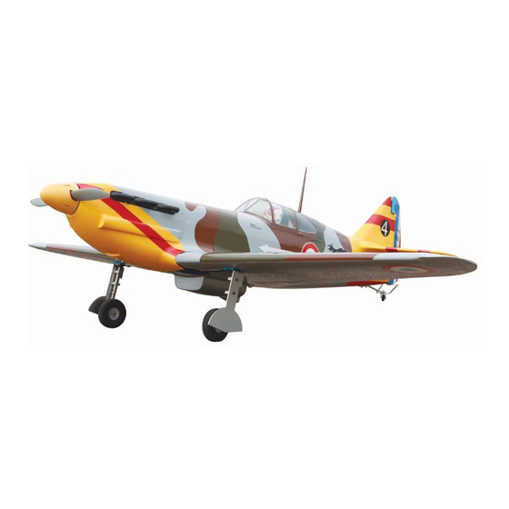
DEWOITINE
D.520
----------------------------1.20 cu.in------------------------------- 4-stroke.
MS:99
Made in Vietnam.
Advertisement
Table of Contents

Related Manuals for Seagull Models DEWOITINE D.520


Summary of Contents for Seagull Models DEWOITINE D.520
- Page 1 DEWOITINE D.520 MS:99 ASSEMBLY MANUAL “Graphics and specfications may change without notice”. Specifications: Wingspan------------------------------------------------70.9 in-------------------------------------- 180cm. Wing area------------------------------------------------764.2sq.in------------------------- 49.3 sq.dm. Approximate flying weight------------------------- 11 lbs---------------------------------------4.6- 5 kg. Length----------------------------------------------------56.8 in----------------------------------- 144.2cm. Recommended engine size----------------------.1.20 cu.in-------------------------------- 2-stroke. ----------------------------1.20 cu.in------------------------------- 4-stroke. Recommended R/C -------------------------------------------- 6 channels with 9 servos. Flying skill level ----------------------------------------------------- Advanced/Intermediate.
- Page 2 . Flying the DEWOITINE D.520 is simply a joy. This instruction manual is designed to help you build a great flying aeroplane. Please read this manual thoroughly before starting assembly of your DEWOITINE D.520 . Use the parts listing below to identify all parts.
- Page 3 This will ensure proper as- 3) Slide the aileron on the wing panel until sembly as the DEWOITINE D.520 is there is only a slight gap. The hinge is now made from natural materials and centered on the wing panel and aileron.
-
Page 4: Hinging The Rudder
Instruction Manual. DEWOITINE Note: Work the aileron up and down several times to “work in” the hinges and check for proper movement. HINGING THE RUDDER. Glue the rudder hinges in place using the same tectniques used to hinge the ailerons. Hinge. - Page 5 www.seagullmodels.com CONTROL HORN M3 SCREW CONTRONL HORN Epoxy. M3 SCREW. ALUMINUM WASHER. Wing Flap Epoxy. ALUMINUM WASHER ALUMINUM WASHER. 18mm. M3 lock nut. Wing Epoxy. M3 LOCK NUT ALUMINUM WASHER Wing 18mm Aileron contronl horn . Epoxy FLAP CONTROL HORN. ELEVATOR CONTROL HORN.
-
Page 6: Engine Mount Installation
Instruction Manual. DEWOITINE Epoxy. Elevator 18mm. Rudder control horn. Elevator control horn. ENGINE MOUNT INSTALLATION. See pictures below.Make yourself the template of your engine on paper. RUDDER CONTROL HORN. Rudder control horn: Using the same tectniques used aileron control horn. See picture below. 1 sets. -
Page 7: Fuel Tank Installation
www.seagullmodels.com Vent tube. Fuel pick up tube. Fuel fill tube. 3) Carefully bend the second nylon tube up at a 45º angle. This tube is the vent tube. 4) Test fit the stopper assembly into the tank. It may be necessary to remove some of the flashing around the tank opening using a INSTALLING THE STOPPER ASSEMBLY. -
Page 8: Installing The Battery
Instruction Manual. DEWOITINE 2) Place your engine onto the engine mount. Adjust the engine is centered of the edges of the engine case. 3) When you are satisfied with the align- ment, mark the locations of the engine mounting. 4) Remove the engine. Using an drill bit, drill the mounting holes through the engine mount at the four locations marked. -
Page 9: Installing The Spinner
www.seagullmodels.com INSTALLING THE SPINNER. The propeller should not touch any part of the spinner cone. If it does, use a sharp modeling knife and carefully trim away the spinner cone where the propel- Trim and cut. ler comes in contact with it. Trim and cut. -
Page 10: Installing The Switch
Instruction Manual. DEWOITINE INSTALLING THE SWITCH. 3/ 32” Hole. Servo tray. Elevator servo. Switch. Rudder servo. Throttle servo. M3 x 10mm. Elevator servo. THROTTLE SERVO ARM INSTALLATION. INSTALLING THE AILERON - FLAP SERVOS. Install adjustable servo connector in the servo Servos. - Page 11 www.seagullmodels.com Wing rib. Wing. Small Weight. Small Weight. String. String. Attach the string to the servo lead and carefully thread it though the wing. AILERON PUSHROD HORN INSTALLATION Wing. 40mm. M2 clevis. M2 lock nut. Aileron. 75mm. Wing Aileron Wing Aileron Aileron.
-
Page 12: Wing Assembly
Instruction Manual. DEWOITINE INSTALLING THE FLAP SERVO. Flap Servo. PUSHROD FLAP INSTALLATION. Wing. 40mm. M2 clevis. M2 lock nut. Flap. 74 mm. Wing Flap Wing Flap Wing. M2 lock nut. WING ASSEMBLY. NOTE: We highly recommend using 30 minute epoxy as it is stronger and provides more working time, allowing the builder to properly align the parts. - Page 13 www.seagullmodels.com 1) Test fit the wing tube into each wing half. Carefully slide the two wing halves together The brace should slide in easily up to the and firmly press them together, allowing the centreline that you drew. If not, use 220 grit excess epoxy to run out.
-
Page 14: Pushrod Installation
Instruction Manual. DEWOITINE Alumium block. Wing bottom. Epoxy. Electric wire. INSTALLING RETRACTABLE LANDING GEAR. PUSHROD INSTALLATION. 190mm. 200mm. 35mm. 17mm. 3 x 25mm. Landing gear. - Page 15 www.seagullmodels.com M3 x 10mm. M3 x 10mm. Wheel Fairing. M3 x 10mm. Open Position. servo arm.
- Page 16 Instruction Manual. DEWOITINE Close Position. 12mm. servo arm. INSTALLING VERITICAL FIN. 1) Remove the covering as picture shown below. Aluminium tube. 3 x 70mm. Fill epoxy. Hinge. Cut. Fill epoxy. Hinge. Hinge.
- Page 17 www.seagullmodels.com Cut. Fill epoxy. Epoxy. 3) Insert aluminium tube into the cardboard of fuselage. 4) Slide the two horizontal fin halves to- gether and carefully align them at the possition Masking tape. on the fuselage. Wipe away any excess epoxy using paper towels.
-
Page 18: Hinging The Elevator
Instruction Manual. DEWOITINE Plastic part. Hinge. C/A glue. ELEVATOR - RUDDER PUSHROD HORN INSTALLATION. Rudder control horn. HINGING THE ELEVATOR. Elevator control horn. Hinge. M2 clevis. M2 Lock nut. Attach to elevator - rudder control horn. Attach to servo arm in fuselage. -
Page 19: Mounting The Tail Wheel
www.seagullmodels.com 1) Elevator and rudder pushrods assembly follow pictures below. Throttle. Elevator. Rudder. Elevator. Control horn. Metal clevis. Rudder. M2 lock nut. Elevator Pushrod. Elevator. Throttle. Rudder pushrod. MOUNTING THE TAIL WHEEL. See picture below. Elevator pushrod. 2) Install servos arm to servos. Notice the position of the servo arms on the servos. - Page 20 Instruction Manual. DEWOITINE 3) Route the antenna in the antenna tube inside the fuselage and secure it to the bot- tom of fuselage using a plastic tape. M3x25 mm. Receiver. 20mm. Battery. M3x30 mm. M3x30mm. ATTACHMENT WING-FUSELAGE. Spring. Tail landing gear. 23mm.
-
Page 21: Control Throws
4.5-5mm. CONTROL THROWS. 1) We highly recommend setting up the DEWOITINE D.520 using the control throws listed at right. We have listed control throws for both Low Rate (initial test flying/sport fly- Wing bolt. ing) and High Rate (aerobatic flying). -
Page 22: Flight Preparation
FLIGHT PREPARATION. 2) Check every bolt and every glue joint in the DEWOITINE D.520 to ensure that Check the operation and direction of the everything is tight and well bonded. elevator, rudder, ailerons and throttle.
Need help?
Do you have a question about the DEWOITINE D.520 and is the answer not in the manual?
Questions and answers