Table of Contents
Advertisement
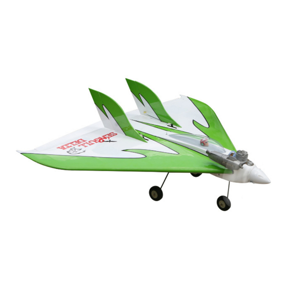
A S S E M B L Y M A N U A L
RACER DELTA 40-46
Code: SEA307
" Graphics and specifications may change without notice " .
Specifications:
Wingspan---------------39.0 in (98.5 cm).
Wing area---------------641.1 sq.in ( 41.4 sq.dm).
Weight-------------------4.4-4.8 lbs (2.0-2.2 kg).
Length-------------------29.3 in (74.3 cm).
Engine-------------------0.40-0.46 cu.in 2 stroke.
Radio--------------------4 channels with 6 servos.
1
Advertisement
Table of Contents

Related Manuals for Seagull Models RACER DELTA 40-46


Summary of Contents for Seagull Models RACER DELTA 40-46
- Page 1 A S S E M B L Y M A N U A L RACER DELTA 40-46 Code: SEA307 “ Graphics and specifications may change without notice ” . Specifications: Wingspan---------------39.0 in (98.5 cm). Wing area---------------641.1 sq.in ( 41.4 sq.dm).
-
Page 2: Kit Contents
You will find that most of the work has been done for you already. The motor mount has been fitted and the hinges are pre-installed. Flying the RACER DELTA 40-46 is simply a joy. This instruction manual is designed to help you build a great flying aeroplane. Please read this manual throughly before starting assembly of your RACER DELTA 40-46. -
Page 3: Additional Items Required
COMBINE THE WINGS. KIT CONTENTS. SEA307 RACER DELTA 40-46 1. Fuselage 2. Rudder 3. Cowling 4. Canopy 5. Pilot 6. Landing gear Fill epoxy on whole wing panel, included hole for wing tube. ADDITIONAL ITEMS REQUIRED. 0.40-0.46 cu in 2 stroke. -
Page 4: Hinging The Aileron
RACER DELTA 40-46 Instruction Manual. HINGING THE AILERON. Note : The control surfaces, including the ai- lerons, elevators, and rudder, are prehinged with hinges installed, but the hinges are not glued in place. It is imperative that you prop- erly adhere the hinges in place per the steps that follow using a high-quality thin C/A glue. -
Page 5: Install The Ailerons
4) Deflect the aileron and completely satu- 8) After both ailerons are securely hinged, rate each hinge with thin C/A glue. The ailer- firmly grasp the wing panel and aileron to ons front surface should lightly contact the make sure the hinges are securely glued and wing during this procedure. -
Page 6: Installing The Aileron Servos
RACER DELTA 40-46 Instruction Manual. Epoxy. Aileron control horn. AILERON PUSHROD INSTALLATION. INSTALLING THE AILERON SERVOS. Please see below pictures. Use a pin vise and a small drill bit to drill small pilot holes in the servo mount for the servo mounting screws. - Page 7 INSTALLING THE MAIN LANDING GEAR TO FUSELAGE.
-
Page 8: Mounting The Tail Wheel
RACER DELTA 40-46 Instruction Manual. Locate the items necessary to install tail gear. Collar. Collar. Collar. MOUNTING THE TAIL WHEEL. - Page 9 14.5mm M3 lock nut. M3 clevis. 16.6mm...
-
Page 10: Hinging The Rudder
RACER DELTA 40-46 Instruction Manual. Collar. HINGING THE RUDDER. Glue three rudder hinges in place using the same techniques used to hinge the ai- Collar. lerons. - Page 11 Rudder fiberglass control horn. INSTALLING THE RUDDER SERVOS. INSTALL RUDDER CONTROL HORN. Repeat steps to install the rudder control horn as same as steps done for ailerons. Fiberglass control horn Because the size of servos differ, you may need to adjust the size of the precut Epoxy.
- Page 12 RACER DELTA 40-46 Instruction Manual. 5) Apply 1-2 drops of thin C/A to each of the mounting tabs. Allow the C/A to cure without using accelerator. 2) Use drill bit in a pin vise to drill the mouting holes in the blocks.
-
Page 13: Installing Vertical Stabilizer
M2x10mm Remove covering. Repeat this procedure to mount the servo in the other panel. INSTALLING VERTICAL STABILIZER 1) Check all alignments. Mark the out- line of the fuselage on vertical stabilizer. 3) Slide the vertical stabilizer back in- place. Using a triangle, check to ensure that the vertical stabilizer is aligned 90º. -
Page 14: Installing The Stopper Assembly
RACER DELTA 40-46 Instruction Manual. 13.5mm Repeat this procedure to mount the servo in the other panel. M3 clevis. M3 lock nut. 15.5mm INSTALLING THE STOPPER ASSEMBLY. 1) Using a modeling knife, carefully cut off the rear portion of one of the 3 nylon Use a felt tip pen to mark the wire where tubes leaving 1/2”... -
Page 15: Fuel Tank Installation
2) Using a modeling knife, cut one length 4) Test fit the stopper assembly into the tank. of silicon fuel line. Connect one end of It may be necessary to remove some of the the line to the weighted fuel pick up and flashing around the tank opening using a the other end to the nylon pick up tube. -
Page 16: Mounting The Engine
RACER DELTA 40-46 Instruction Manual. 7) Slide the fuel tank into the fuselage. Guide the lines from the tank through the hole in the firewall. Thread locker glue. MOUNTING THE ENGINE. 8) Use balsa block to hold in place the fuel... - Page 17 3) Use a drill to drill the four holes in the engine mount rails. Pushrod wire. THROTTLE SERVO ARM Machine screw 3x20mm INSTALLATION. Install adjustable servo connector in the 4) On the fire wall has the location for the servo arm as same as picture below: throttle pushrod tube (pre-drill).
- Page 18 RACER DELTA 40-46 Instruction Manual. COWLING. Carefully trim the cowling to fit over the engine. Use the photo here and those on the box as a guide. The photo shows the completed engine installation as a refer- ence for all the trimming necessary to fit the cowl over the engine.
- Page 19 1) Tape the cowl to the fuselage using low-tack tape. 2) Use a drill and drill bit to drill the holes for the cowl mounting screws. Make sure the cowl position is correct before drill- ing each hole. 3x10mm Because of the size of the cowl, it may be nec- essary to use a needle valve extension for the high speed needle valve.
- Page 20 RACER DELTA 40-46 Instruction Manual. ELECTRIC POWER CONVERSION. 1) Locate the items neccessary to install the electric power conversion included with your model. M4x20mm 2) Recommend the items necessary to in- stall the electric power conversion parts included with your model.
- Page 21 Blind nut. Speed control. M3x15mm 5) Attach the speed control to the side of the motor box using two-sided tape and tie wraps. Connect the appropriate leads from the speed control to the mo- tor. Make sure the leads will not interfere with the operation of the motor.
-
Page 22: Installing The Spinner
RACER DELTA 40-46 Instruction Manual. Battery. Open the air exit hole. 3x10mm and washer. 3x10mm and washer. INSTALLING THE SPINNER. Tie wraps. Install the spinner backplate, propeller and spinner cone. - Page 23 INSTALLATION PILOT AND WINDSHIELD. 1) Locate items necessary to install pilot and windshield. The propeller should not touch any part of the spinner cone. If it does, use a sharp modeling knife and carefully trim away the spinner cone where the propel- ler comes in contact with it.
- Page 24 RACER DELTA 40-46 Instruction Manual. 3) Position the pilot figure on the cock- 2) If all the decals are not precut, please pit floor as shown. Use epoxy to glue the use scissors or a sharp hobby knife to cut base of the pilot figure, please see pictures the decals from the sheet.
-
Page 25: Control Throws
Lift the model. If the tail drops when CONTROL THROWS. you lift, the model is “tail heavy” and you must add weight* to the nose. If the nose drops, it is “nose heavy” and you must add weight* to the tail to balance. Ailerons: Rudder: High Rate :... -
Page 26: Flight Preparation
An out of balance propeller will cause If it does not, flip the servo reversing excessive vibration which could lead switch on your transmitter to change to engine and/or airframe failure. the direction. We wish you many safe and enjoyable flights with your RACER DELTA 40-46. - Page 27 If you have any queries, or are interested in our products, please feel free to contact us Factory : 12/101A - Hamlet 4 - Le Van Khuong Street - Dong Thanh Ward - Hoc Mon District - Ho Chi Minh City - Viet Nam. Office : 62/8 Ngo Tat To Street - Ward 19 - Binh Thanh District - Ho Chi Minh City - Viet Nam Phone : 848 - 86622289 or 848- 36018777...
Need help?
Do you have a question about the RACER DELTA 40-46 and is the answer not in the manual?
Questions and answers