Table of Contents
Advertisement
Quick Links
"An American Tradition Since 1954!"
MODEL VF-2XP & VF3iXP
®
BROASTER
VENTLESS FRYER
INSTALLATION & OPERATION MANUAL
Be sure ALL installers read, understand, and have access to this manual at all times.
®
,
®
®
®
®
Broaster
,
Broasted
, Broaster Chicken
, Broaster Foods
, and Broasterie
are registered trademarks.
Usage is available only to licensed operators with written authorization from The Broaster Company.
The Broaster Company
2855 Cranston Road, Beloit, WI 53511-3991
608/365-0193 www.broaster.com
Design Certified By:
ETL (US & CAN), ETL Sanitation
16887 4/09
Copyright 2006 The Broaster Company
Printed in U.S.A.
Advertisement
Table of Contents

Related Manuals for Broaster VF3iXP


Summary of Contents for Broaster VF3iXP
- Page 1 , Broaster Chicken , Broaster Foods , and Broasterie are registered trademarks. Usage is available only to licensed operators with written authorization from The Broaster Company. The Broaster Company 2855 Cranston Road, Beloit, WI 53511-3991 608/365-0193 www.broaster.com Design Certified By: ETL (US &...
- Page 3 All adjustments and repairs shall be made WARNING: Rags or papers containing by an authorized Broaster Company repre- cooking oil can catch fire if exposed to sentative. heat. Laundering will not remove the oil. Dis-...
- Page 5 NEW OWNER OR RELOCATION NOTIFICATION If you are a new owner of a used unit or This card enables The Broaster Company to better serve you and keep you informed of ® have relocated your Broaster VF-2 or VF3i changes in equipment, condiments, or ser- Fryer, please take a minute to fill out one of vice bulletins.
- Page 6 The Broaster Company 2855 Cranston Road Beloit, WI 53511 The Broaster Company 2855 Cranston Road Beloit, WI 53511 Manual #16887 5/08...
-
Page 7: Table Of Contents
VF-2 EXPORT & CE ................... 2 - 4 VF3i EXPORT & CE.................... 2 - 5 INITIAL START-UP...................... 2 - 6 ® 2 - GETTING TO KNOW YOUR BROASTER VF-2 or VF-3i FRYER......2 - 1 4 - PRE-COOKING PREPARATION................... 4 - 1 START-UP........................4 - 1 COOKING OIL ...................... - Page 8 6 - FIRE SUPPRESSION SYSTEMS.................. 6 - 1 GENERAL DESCRIPTION ..................6 - 1 AUTOMATIC OPERATION ..................6 - 1 MANUAL OPERATION ....................6 - 1 INSPECTION & MAINTENANCE................6 - 1 Gaining Access ....................6 - 1 Monthly Inspection ....................6 - 2 Semi-Annually .....................
-
Page 9: Owner Responsibility
Allow only properly trained personnel to Broaster Company should be contacted at ® operate, clean and maintain a Broaster ® the time of sale or disposal of the Broaster VF-2, VF-3i Fryer. VF-2, VF-3i Fryer so records may be updated. •... -
Page 11: Installation
2 - INSTALLATION As you progress through the set-up of your VF-2, VF-3i fryer, refer to Chapter 4, GETTING TO ® KNOW YOUR BROASTER VF-2, VF-3i FRYER for part descriptions and locations. LOCATION CLEARANCES Recommended clearances are: For convenience and speed, location of the Left Side: 0”... -
Page 12: Fire Suppression Activation
DO NOT operate the unit. The Fire Suppression System will not func- tion to a satisfactory level. Contact autho- rized Broaster Company representative. 10. Inside the Electrical Control area, locate strap securing Fire Suppression Arming Pin. Cut and remove the strap. -
Page 13: Electrical Characteristics
ELECTRICAL CHARACTERISTICS ELECTRICAL CONNECTIONS The unit is available for 120/240 VAC or Applied voltage should match dataplate 120/208 VAC applied voltage, 30 amp, listed voltage. 60Hz, 1 phase electrical connection in the USA and Canada. (4 wire with neutral and The electrical schematics can be found on ground) pages 4 thru 7 of this section. -
Page 14: Wiring Diagram Vf-2 Export & Ce
WIRING DIAGRAM - VF-2 EXPORT & CE 2 - 4 Manual #16887 5/08... -
Page 15: Vf3I Export & Ce
WIRING DIAGRAM - VF-3i EXPORT & CE 2 - 5 Manual #16887 5/08... -
Page 16: Initial Start-Up
INITIAL START-UP 13. Fill Cooking Pot with cooking oil and place in unit. VF2 - 14 lbs VF3i - 21 lbs 14. Lower Element into Cooking Pot and hang Platform on Platform Lift Arm. Oil fill should be at cold level. Add or remove oil as needed. -
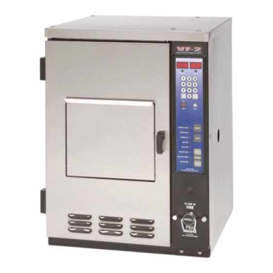
Page 17: Getting To Know Your Broaster
7. Electrical Control Access Panel: Removable panel to allow access to unit control devices. WARNING: This panel should only be removed by an authorized Broaster Company representative. Electrical hazard could result in serious injury or death. Dis- connect main power to unit before remov- ing. - Page 18 10. Splash Tray: Catches oil that escapes 18. Element: Heats the oil in the Cooking from the Cooking Pot or over flows. Pot. WARNING: Hot shortening! Hot 19. Element Retainer: Holds the element shortening could splash causing seri- in the raised position when the Ele- ous burns.
- Page 19 side of panel) 29. Fire Extinguisher: Capable of extin- 34. Air Filter Differential Pressure Switch: guishing a grease fire. Indicates an unacceptable level of air flow through the Air Filter by measuring 30. Fire Extiguisher Pressure Switch: pressure drop through filter. If pres- Monitors pressure within Fire Extigu- sure drop exceeds maximum set value, isher.
-
Page 20: Pre-Cooking Preparation
4 - PRE-COOKING PREPARATION START-UP ® ® Bro-Oil Fill cooking well with Broaster liq- uid oils or a high quality liquid oil manufac- tured for deep frying. Fill cooking well to CAUTION: Check oil level before pressing the ON button. -
Page 22: Control Panel
5 - CONTROL PANEL DUAL DISPLAY FAMILIARIZATION 5. Basket Down Indicator Light: Illumi- nates when Food Basket is in lowered position. 6. Time Display: Shows time countdown during a cook cycle, program values during programming and programmed time during idle period. 7. -
Page 23: Operational Lockout
OFF button and DO NOT attempt to operate until it has been serviced by an authorized Broaster Company representative. 22. Fire System Light: Illuminates when 6 months have passed to indicate semi- annual maintenence is due on fire sup- pression system. -
Page 24: Preset Cook Mode
Set Time: PRESET COOK MODE Action: Press Cook Time Button twice Choose Preset Cook Cycle: within 5 seconds. Action: Press a button, 0 thru 9, corre- Response: Programming mode has sponding to the desired preset. been entered. Flashing Time Display reads “##:##.”... - Page 25 Change Cook Time: Advance to Next Preset: Action: Press the TIME button once. Action: Press the RESET button once. Response: The TEMP display will turn Response: The CYCLE COUNT dis- off and only the TIME display will flash. play will change to “-1” and the presets for #1 will be displayed.
-
Page 26: Fire Suppression Systems
6 -FIRE SUPPRESSION SYSTEM GENERAL DESCRIPTION NOTE: If the pressure in the cylinder drops below 195 psi, the pressure switch opens, The Fire Suppression system is specifically deactivating the power relay cutting all designed for controlling wet chemical fires in power to the fryer. -
Page 27: Monthly Inspection
The inspection should be conducted by the owner/operator or authorized 3. Examination of the fire extinguisher. If Broaster Company representative. The fol- it is low, recharge the system. lowing items must be checked and verified during the monthly inspection: 4. -
Page 28: Twelve Year
NOTE: Certified service personnel can gen- erally be found locally through authorized suppliers of fire extinguishing equipement in yellow pages or call your Broaster Distribu- tor for sources. 3. If the cylinder shows no signs of rup- ture or distortion, recharge the Fire Suppression system in accordance with NFPA 17A guidelines. -
Page 29: Semi-Annual Inspection & Maintenance Log
SEMI-ANNUAL INSPECTION & MAINTENANCE LOG Fryer Serial No. _____________ Date __________ I & M by __________ Date __________ I & M by __________ Date __________ I & M by __________ Date __________ I & M by __________ Date __________ I & M by __________ Date __________ I &... - Page 30 7 - VENTILATION SYSTEM AIR FILTER REPLACEMENT Note: Replace every 3 Months or sooner if needed. 1. Open access door. 2. Unlatch filter tray and pull tray out (about 1.50”) with your free hand under °. the tray and swing tray down 45 3.
-
Page 32: Cooking Oil Care
9 - COOKING OIL CARE IMPORTANT Oil Replacement: How can you tell if oil > Store cooking oil at room temperature: should be replaced? It will show signs of 65° - 75° F. increased smoking or foaming. If not dis- carded, safety and product quality could be >... - Page 34 10 - CLEANING PROCEDURES MINIMUM CLEANING REQUIREMENTS DAILY WEEKLY DETAILS Clean Cooking Pot Dishwasher Soak 12-2 Clean Grease Filter 12-3 Clean Filter Tray 12-3 Clean Splash Tray 12-3 Clean Food Basket Soak 12-2 Clean Basket Lift Platform Soak 12-2 Clean Cooking Area 12-3 Filter/Strain Cooking Oil 11-1...
- Page 35 COOKING CHAMBER PARTS DISHWASHER SAFE COMPONENTS The Splash Tray, Product Door, Access 1. Press power OFF and disconnect main Door, Cooking Pot, Basket Lift Platform, Fil- power supply and allow cooking oil to ter Tray and Grease Filter can be removed cool completely.
-
Page 36: Unit Surfaces
Broaster Cooking Well Cleaner (P/N 99500 or 92643) to 1 gallon of warm tap water. ® DANGER: Broaster Cooking Well Cleaner is a caustic substance. DO NOT take internally. Keep away from eyes and skin. DO NOT inhale powder. Wear rubber gloves and eye protection when han- dling. -
Page 38: Season Shutdown
11 - DAILY SHUTDOWN / SEASON SHUTDOWN WARNING: Rags or papers containing cooking oil can catch fire if ex- posed to heat. Laundering will not remove the oil. Dispose of all oil- soiled papers and rags in a trash container that is in a ventilated area away from all cooking equipment or other heat sources such as direct sunlight. -
Page 40: Troubleshooting
12 - TROUBLESHOOTING All adjustments and repairs shall be made by an authorized Broaster Company representative. ELECTRICAL TIPS COMPLAINT CAUSE REMEDY 1. Unit OFF 1. Press ON button 2. Main power OFF 2. Turn ON POWER light not illumi- 3. Unplugged 3. -
Page 41: Indicator Lights
INDICATOR LIGHTS The series of indicator lights on the Display Panel check for specific conditions that make the VF-2 fryer safe to operate. The unit will not start or continue a cook cycle if any of the following indicator lights are lit. COMPLAINT CAUSE REMEDY... -
Page 42: Solid State Controller Tips
SOLID STATE CONTROLLER TIPS COMPLAINT CAUSE REMEDY 1. There is a controller fail- 1. Push power OFF button Display reads FAIL Contact service person 1. Oil temperature too high 1. Push power OFF button Display reads HI Contact service person 1.
Need help?
Do you have a question about the VF3iXP and is the answer not in the manual?
Questions and answers