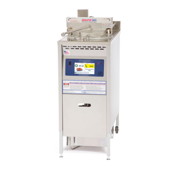
Broaster 1800 Service Manual
Pressure fryer w/smart touch control
Hide thumbs
Also See for 1800:
- Service manual (131 pages) ,
- Operation manual (57 pages) ,
- Installation manual (56 pages)
Table of Contents
Advertisement
Quick Links
SERVICE MANUAL
®
BROASTER
1600 AND 1800
PRESSURE FRYER w/SMART TOUCH CONTROL
Be sure ALL installers read, understand, and have access to this manual at all times.
1600
1800
Genuine Broaster Chicken®, Broasted®, Broaster Chicken®, Broaster Foods®. and Broasterie® are registered
trademarks. Usage is available only to licensed operators with written authorization from the Broaster Company.
Broaster Company
2855 Cranston Road, Beloit, WI 53511-3991
608/365-0193 broaster.com
Design Certified By:
© 2013 Broaster Company
1600: CSA, NSF and UL
Manual #17270 10/13 Rev 9/16
Printed In U.S.A.
1800: CSA (AGA & CGA), NSF and UL
Advertisement
Table of Contents

Related Manuals for Broaster 1800


Summary of Contents for Broaster 1800
- Page 1 Be sure ALL installers read, understand, and have access to this manual at all times. 1600 1800 Genuine Broaster Chicken®, Broasted®, Broaster Chicken®, Broaster Foods®. and Broasterie® are registered trademarks. Usage is available only to licensed operators with written authorization from the Broaster Company. Broaster Company 2855 Cranston Road, Beloit, WI 53511-3991 608/365-0193 broaster.com Design Certified By: ©...
- Page 3 All adjustments and repairs shall be made If at any time the POWER by an authorized Broaster Company repre- ON light does not turn off sentative. when the cook/filter switch is moved to...
- Page 4 CSA 1.8 to guard against transmission of strain to the gas connectors. Failure to restrain the fryer could allow it to move, causing hot shortening to spill out, or a possible break in the gas line causing an explosive condition. broaster.com Manual #17270 10/13 Rev: 10/15...
-
Page 5: Table Of Contents
TABLE OF CONTENTS 1 - WARNING SIGNS AND LABELS 1600 ........................1 - 1 1800 ........................1 - 2 Pictures ........................1 - 3 2 - ELECTRIC POWER SUPPLY WIRING DIAGRAMS Electrical Connection - Single and Three Phase Power Connection ....2 - 1 DOMESTIC 1600/1800E ST ................ - Page 6 EXHAUST TANK ...................... 6 - 2 EXHAUST TUBE...................... 6 - 3 PRESSURE REGULATING VALVE ................. 6 - 4 7 - 1800 PRESSURE SYSTEM SYSTEM FAMILIARIZATION ................... 7 - 1 EXHAUST DRAIN TUBE ..................7 - 2 EXHAUST TANK ...................... 7 - 2 EXHAUST TUBE......................
- Page 7 PRESSURE SYSTEM TIPS ..................10 - 4 PRODUCT TIPS ..................... 10 - 5 FILTERING TIPS ..................... 10 - 7 FLOW CHART - 1600 & 1800E ................10 - 8 FLOW CHART - 1800GH ..................10 - 9 broaster.com Manual #17270 10/13 Rev 3/16...
-
Page 9: Broaster.com Manual #17270 10/13 Rev
Broaster be sure all safety devices and warning signs Company representative or The Broaster are in place and legible. If not, The Broaster Company Service Department at 608/365- Company should be notified in writing of the 0193. - Page 10 1800 Domestic Labeling CAUTION: DO NOT OPERATE THIS FR YER WITH OUT FILT ER PAN & COVER IN PLACE CAUTION broaster.com Manual #17270 10/13 Rev 12/14...
- Page 11 Item 1 - Part #10733 Item 2 - Part #10886 Item 3 - Part #11027 Item 4- Part #16368 Item 5 - Part #11073 broaster.com Manual #17270 10/13 Rev 12/14...
- Page 12 Item 13 - (1800GH after July 2003) #15777 for Nat Gas #16993 for LP Gas Item 9 - Part #10900 CAUTION: DO NOT OPERATE THIS FRYER WITHOUT FILTER PAN & COVER IN PLACE Item 10 - Part #15785 broaster.com Manual #17270 10/13 Rev 12/14...
- Page 13 2. MOVE SLIDE SWITCH ON GAS VALVE TO "OFF". 3. TURN THE MANUAL SHUT-OFF VALVE TO THE "OFF" POSITION. INSTALL IN ACCORDANCE WITH AMERICAN NATIONAL STANDARD FUEL GAS CODE ANSI Z223. 1 LATEST ADDITION Item 14 - Part #15694 Domestic broaster.com Manual #17270 10/13 Rev 12/14...
-
Page 15: Electric Power Supply
Be sure main circuit breaker panel. is ON and main fuses are good. Correct voltage will be either 208 or 240V. WIRING DIAGRAMS Three and Single Phase Wiring Connections: 1Ph. 50/60Hz 3Ph 50/60Hz broaster.com Manual #17270 10/13 rev 6/15... - Page 16 DOMESTIC - 1600 and 1800E SmartTouch broaster.com Manual #17270 10/13 rev 6/15...
-
Page 17: Export 1600Xp St
EXPORT 1600XP SmartTouch broaster.com Manual #17270 10/13 rev 5/16... -
Page 18: Export 1800Exp St
EXPORT 1800EXP SmartTouch broaster.com Manual #17270 10/13 rev 5/16... -
Page 19: Domestic 1800Gh St
DOMESTIC - 1800GH SmartTouch broaster.com Manual #17270 10/13 rev 5/16... -
Page 20: Export 1800Ghxp St
EXPORT - 1800GHXP SmartTouch broaster.com Manual #17270 10/13 rev 5/16... -
Page 21: Smart Touch Control Panel
(Cook, Filter, Setup and Help) to help you will appear. Enter the number of the month setup and use your fryer. and press the enter key. Repeat this action This tab is the main working screen. From broaster.com Manual #17270 10/13 Rev 12/14... -
Page 22: Cook Tab
2. After a filtering cycle. tabs across the top of the display. “CUS- 3. When a preset is selected and the oil TOM” indicates you are in manual cooking temperature is not at the preset tempera- mode. ture. broaster.com Manual #17270 10/13 Rev 12/14... -
Page 23: Select Preset Display
5 loads. There are 2 “Select Preset” boxes. This box indicates how many cook cycles All of the Broaster Company Products are have been done since the last time the oil preloaded into the memory of the control was filtered. It is active and can be pressed... -
Page 24: Filter Tab
When it reaches 5:00 minutes an alert sounds and a reminder flashes (see below) to close the drain valve. To silence the alert press the button with the speaker on it. DO NOT press the Stop Pump button. broaster.com Manual #17270 10/13 Rev 12/14... -
Page 25: Setup Tab
Repeat this action for the Day, Year, Hours, Minutes, Seconds, AM and PM boxes. When finished press the green OK button. To leave this display without making a change press the red X or the green OK. broaster.com Manual #17270 10/13 Rev 12/14... -
Page 26: Energy Save Setting
ON or OFF. returns to the normal Cook Tab display and the temperature will be yellow and Low and the set temp will be alternating. DO NOT start cooking until the temp display is green. broaster.com Manual #17270 10/13 Rev 12/14... -
Page 27: Presets
Cook Tab. Creating a new product or deleting a prod- uct on the list will be described later. broaster.com Manual #17270 10/13 Rev 12/14... -
Page 28: Active
When the export is complete the box will Press the green OK button to save the new say “Menu Exported”. Press the OK button product. and the Preset display will appear. Remove the flash drive from the USB port. broaster.com Manual #17270 10/13 Rev 12/14... -
Page 29: Load Menu
Pressing this option will allow you to ton and the Preset display will appear. change the language used in all displays. (This option is not yet active) Remove the flash drive fro the USB port. broaster.com Manual #17270 10/13 Rev 12/14... -
Page 30: Alert Settings
2. After a filter cycle has been completed this reminder will appear after the oil comes up to the set temperature. 3. If the fryers has been setting idle for 2 3-10 broaster.com Manual #17270 10/13 Rev 12/14... -
Page 31: Calibration
PIN code 0540 and press Enter. Cook Filter Setup Help Time & Date Adjustment Language Selection Temperature Alert Settings Energy Save Setting Counter / Totalizers Pin Maintenance Diagnostics Presets Enter Service Contact Info Shortening Management Exit Setup 3-11 broaster.com Manual #17270 10/13 Rev 12/14... -
Page 33: Power Input Box
4 - POWER INPUT BOX 1600 Pressure Fryer: 1800E Pressure Fryer: broaster.com Manual #17270 1013 Rev 12/14... -
Page 34: Contactors (1600/1800E)
“Heat On”. Make same checks as in step 4 between any two of the three connections on element wire side of contactor. Any drop in voltage indi- cates a poor or dirty contact within the contactor. broaster.com Manual #17270 1013 Rev 12/14... -
Page 35: Fuse (1600/1800E)
3. Check between two terminals of fuse holder with an ohmmeter. Meter should indicate a closed circuit. If not, fuse may be faulty. Fuse Replacement: 1. Remove end cap (5) and replace fuse (6). Continued: broaster.com Manual #17270 1013 Rev 12/14... -
Page 36: Broaster.com Manual #17270 10/13 Rev
(14). 8. From inside the cooking well, slide ele- ment out and lift on end to remove. Squeeze slightly to clear neck of cook- ing well. 1800E: broaster.com Manual #17270 1013 Rev 12/14... -
Page 37: Limit Switch
1. See ACCESS FOR SERVICE. 2. Remove wires from switch. 3. Remove two mounting screws. 4. Install new switch in reverse order. Be sure all wire connections are secure and in their original location. broaster.com Manual #17270 1013 Rev 12/14... -
Page 38: Transformer (1800Gh)
Meter should indi- cate a closed circuit, If not, trans- former is faulty. 4. Check between the two secondary wires with an ohmmeter. Meter should indicate a closed circuit. If not, trans- former is faulty. broaster.com Manual #17270 1013 Rev 12/14... -
Page 39: Cover And Yoke
When handle is rotated, cam (3) moves cover (4) in or out of the cooking well. Cam and spacer block (5) lock the cover when pressure in cooking well pushes up on the cover. broaster.com Manual #17270 10/13 Rev 12/14... -
Page 40: Familiarization
FAMILIARIZATION broaster.com Manual #17270 10/13 Rev 12/14... -
Page 41: Adjustments
With cover in CLOSED posi- tion, tighten each cover bolt a little at a time while alternating between the two. 4. Using a torque wrench, tighten each bolt to a maximum torque of 180 in/lbs or 15 ft/lbs. broaster.com Manual #17270 10/13 Rev 9/16... -
Page 42: Removal
2. Loosen screws (9) attaching splash guard (10) to back panel assembly (11). 3. Slide splash guard (10) forward and up towards the end of the cover handle (2). Continued: broaster.com Manual #17270 10/13 Rev 12/14... -
Page 43: Assembly
9. Use a 1/8 inch punch to remove 7. Rotate cover handle to the CLOSED grooved pin. Remove handle and cam. position. 10. Clean lifter box, handle, cam and yoke bar where lifter box slides up and down. Continued: broaster.com Manual #17270 10/13 Rev 12/14... -
Page 44: Pressure Gauge
12. Pull cover forward. If yoke latch (6) and latch columns (7) do not line up, adjust slide rod (13) to the left or right. 13. Center cover within the cooking well. See Centering Cover. broaster.com Manual #17270 10/13 Rev 12/14... -
Page 45: Safety Relief Valve
Escaping steam could cause serious burns. 1. See PROPER COVER OPERATION. Replacement: Replacement valve must have a 15 PSI relief pres- sure. 1. OPEN cover and pressure regulating valve. 2. Unscrew valve (1) from the cover. broaster.com Manual #17270 10/13 Rev 12/14... -
Page 47: 1600 Pressure System
Excess coating can collect in pressure regulating valve and exhaust tank. • Overfilling cooking well with oil: See operation manual for correct oil level. broaster.com Manual #17270 10/13 Rev 12/14... -
Page 48: Exhaust Drain Tube
(1) meets tank. Tank will then become filled with liquid. Liquid may be forced up the stack (3) when pressure is released at the end of a cooking cycle. broaster.com Manual #17270 10/13 Rev 12/14... -
Page 49: Exhaust Tube
12-14 psi during a cooking cycle. Pressure may build slowly or remain low when cooking small loads. Add one or two quartered potatoes with product to help build and maintain maximum pressure. broaster.com Manual #17270 10/13 Rev 12/14... - Page 50 7. Install new parts from the repair kit. cooking well. Using a screwdriver, turn Lubricate all O-rings and contacting stem assembly (11) either clockwise or surfaces with olive oil. counterclockwise to obtain this dis- tance. 10. Tighten locking nut. broaster.com Manual #17270 10/13 Rev 12/14...
-
Page 51: 1800 Pressure System
7 - 1800 PRESSURE SYSTEM DO NOT attempt to • Overloading basket with product: Oil tighten, repair, or replace level will raise too high. any fitting, line or component unless main electric power is disconnected, • Breading then dropping: Excess coat-... -
Page 52: Exhaust Drain Tube
(1) is con- 8. Assemble in reverse order. nected. Tank will then become filled with liquid. Liquid may be forced up the stack (3) when pressure is released at the end of a cooking cycle. broaster.com Manual #17270 10/13 Rev 12/14... -
Page 53: Exhaust Tube
12-14 psi during a cooking cycle. Pressure may build slowly or remain low when cooking small loads. Add one or two quartered potatoes with product to help build and maintain maximum pressure. broaster.com Manual #17270 10/13 Rev 12/14... -
Page 54: Broaster.com Manual #17270 10/13 Rev
7. Install new parts from the repair kit. turn stem assembly (11) either clock- Lubricate all O-rings and contacting wise or counterclockwise to obtain this surfaces with olive oil. distance. 10. Tighten locking nut. broaster.com Manual #17270 10/13 Rev 12/14... -
Page 55: 8- 1800Gh Main Burner System
To convert from one type of gas to another, five components must be changed: gas valve, pilot burner orifice, main burner orifice and gas data plate. Notify Broaster Com- pany Service Department of a conversion in writing. Main Burner Orifice Sizes Up To 2000 Feet Above Sea Level: 1. -
Page 56: Ventilation
OFF to stop all gas flow, and ON allows gas flow to pilot and main burners as needed. Adjustment for gas pressure and gas flow to pilot burner are also found on the valve. broaster.com Manuals #17270 10/13 Rev 12/14... - Page 57 24VAC between the blue and red wire and the blue and yellow wire. (see below) 5. Refer to the TROUBLESHOOTING FLOW CHART on page 11-10 if there is no voltage at either or both places. broaster.com Manuals #17270 10/13 Rev 12/14...
-
Page 58: Flame Adjustments
4. Turn gas shut off valve (1) ON. 5. Light pilot see MODEL 1800GH LIGHTING INSTRUCTIONS. Turn gas valve switch (2) ON. Check cooking oil level before turning power switch on . 6. Turn cook/filter switch to COOK. broaster.com Manuals #17270 10/13 Rev 12/14... -
Page 59: Air Shutter
2. Screw shutter (14) in or out to obtain a blue flame. Flame should start burning slightly above main burner. 6. Loose venturi (11) or bad gasket (12) can affect combustion. Tighten or 3. Tighten locknut. replace gasket. broaster.com Manuals #17270 10/13 Rev 12/14... -
Page 60: Combustion Chamber
10. Remove screws (22) on both sides of and manual gas shut off valve OFF. inner jackets and remove. 2. Turn main gas supply OFF. 11. Clean exhaust flue, inner jacket, outer wall and cooking well. 12. Assemble in reverse order. broaster.com Manuals #17270 10/13 Rev 12/14... -
Page 61: Main Burner Orifice
12. Assemble in reverse order. Adjust air shutter. See AIR SHUTTER. Check all connections and pipes with a soap and water solution. Bubbles indicate a gas leak. broaster.com Manuals #17270 10/13 Rev 12/14... -
Page 62: Pilot Burner Orifice
5. Remove orifice (26). 6. Install new orifice in reverse order. Check all gas connections with a soap and water solution. Bubbles indicate a gas leak. broaster.com Manuals #17270 10/13 Rev 12/14... -
Page 63: Drain Valve And Filter System
(5). 5. Remove nipple (7) from drain valve. 6. Unscrew drain valve from the cooking well (6). 7. Assemble in reverse order using #15820 Primer & #15359 Sealant on cooking well threads. broaster.com Manual #17270 10/13 Rev 12/14... -
Page 64: Filter Pan
Correct order is filter screen (7) on bottom of filter pan, filter paper (8), filter hold-down (9), one cup (1600) or two cups ® (1800) of Broaster filtering compound on top of filter paper and cover (10) on filter pan. broaster.com Manual #17270 10/13 Rev 12/14... -
Page 65: Check Valve
2. Drain cooking oil from the cooking well and into a container made for handling hot oil then close the drain valve. 1800: 3. Remove left hand side panel (1800). 1600: 1. Use a clean cloth or paper towel to 1800:... -
Page 66: Motor
Motor has a manual reset thermal overload. essary binding on shafts of the pump If overload trips, push red reset button on and motor. back after motor has cooled. Turn power switch OFF before resetting manual reset thermal overload. broaster.com Manual #17270 10/13 Rev 12/14... - Page 67 MOTOR WIRING: Be sure motor is wired for correct voltage and correct direction. See below for correct wire connections. DOMESTIC & EXPORT EUROPEAN UNION = WIRENUT broaster.com Manual #17270 10/13 Rev 12/14...
-
Page 68: Pump
Turn gears by hand for good oil coverage. 2. See MOTOR Installation Hints. 2. Be sure cover O-ring is in place before tightening bolts. broaster.com Manual #17270 10/13 Rev 12/14... -
Page 69: 10 - Troubleshooting
10 - TROUBLESHOOTING All adjustments and repairs shall be made by an authorized Broaster Company representative. ELECTRICAL TIPS COMPLAINT CAUSE REMEDY 1. Open probe circuit 1. Replace probe 2. Probe wires reversed 2. Correct wiring Probe Fault 3. Probe changes more than 3. -
Page 70: Smart Touch Controller Tips
Internal fault detected * Call for service * Call for service INTERNAL FAULT Display reads C1 contactor is stuck in * Call for service * Call for service C1 FAULT the closed position 10-2 broaster.com Manual #17270 10/13 Rev 3/16... - Page 71 2. Gas control OFF 2. Turn ON Main burner won’t ignite 3. Controller in Filter, Setup 3. Press COOK tab or Help mode 4. Controller in Filter, Setup 4. Press COOK tab. or help mode. 10-3 broaster.com Manual #17270 10/13 Rev 12/14...
-
Page 72: Cover And Yoke Tips
2. Pressure regulating valve 2. Contact service person No pressure dirty or blocked open 3. Leaks around cover O- 3. Replace O-ring ring 1. Turn power switch OFF. Excess pressure Contact service person. 10-4 broaster.com Manual #17270 10/13 Rev 12/14... -
Page 73: Product Tips
2. Old product 2. Discard 1. Product stuck together 1. Float basket while load- White spots 2. Food basket overloaded 2. Decrease load size Dark spots 1. Dirty oil 1. Filter or replace 10-5 broaster.com Manual #17270 10/13 Rev 12/14... -
Page 74: Filtering Tips
1. See COOKING OIL CARE pumping when oil is level installed or crumbs under AND FILTERING with top of hold down, filter paper or hold down approximately 1 inch of oil in bottom 10-6 broaster.com Manual #17270 10/13 Rev 12/14... - Page 75 SERVICE NOTES broaster.com Manual #17270 10/13...
- Page 76 SERVICE NOTES broaster.com Manual #17270 10/13...
- Page 77 SERVICE NOTES broaster.com Manual #17270 10/13...
- Page 80 Broaster Company 2855 Cranston Road, Beloit, WI 53511-3991 608/365-0193 broaster.com...
Need help?
Do you have a question about the 1800 and is the answer not in the manual?
Questions and answers