Advertisement
Quick Links
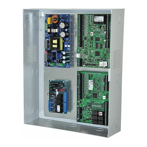
Access & Power Integration
Trove1M1
- Trove1 enclosure with Altronix/Lenel backplane (TM1)
TM1
- Altronix/Lenel backplane only
Trove2M2
- Trove2 enclosure with Altronix/Lenel backplane (TM2)
TM2
- Altronix/Lenel backplane only
TMV2
- Altronix/Lenel Door Backplane. Fits Trove2 and Trove3 enclosures
Trove3M3
(not evaluated by UL)
- Trove3 enclosure with Altronix/Lenel backplane (TM3)
TM3
(not evaluated by UL)
- Altronix/Lenel backplane only
Installation Guide
All registered trademarks are property of their respective owners.
Rev. TMERC101817
Installing Company: _____________________ Service Rep. Name: __________________________________________
Address: ________________________________________________________ Phone #: _________________________
SIGNALING
More than just power.™
Advertisement

Subscribe to Our Youtube Channel
Related Manuals for Altronix Trove1M1


Summary of Contents for Altronix Trove1M1
- Page 1 - Altronix/Lenel backplane only Trove2M2 - Trove2 enclosure with Altronix/Lenel backplane (TM2) - Altronix/Lenel backplane only TMV2 - Altronix/Lenel Door Backplane. Fits Trove2 and Trove3 enclosures Trove3M3 (not evaluated by UL) - Trove3 enclosure with Altronix/Lenel backplane (TM3) (not evaluated by UL)
-
Page 2: Specifications
Overview: Altronix Trove1M1, Trove2M2 and Trove3M3 accommodate various combinations of Lenel boards with or without Altronix power supplies and sub-assemblies for access systems. Specifications: Trove1M1 Trove1 enclosure with TM1 Altronix/Lenel backplane. • 16 Gauge enclosure with ample knockouts for convenient access. - Page 3 Install the two/three lower screws and make sure to tighten all screws. 3. Mount included UL Listed tamper switch(es) (Altronix Model T112 or equivalent) in desired location, opposite hinge. Slide the tamper switch bracket onto the edge of the enclosure...
- Page 4 Altronix Power Supplies/Chargers and/or Sub-Assemblies: 1. Fasten standoffs (provided) to pems that match the hole pattern for Altronix Power Supply/Chargers or Altronix Sub-Assembly boards (positions (B) and (C), Fig. 2, pg. 4). Use snap on nylon standoffs for the upper two mounting holes in the board.
- Page 5 TM2 Sub-Assembly Position Chart for the Following Models: Altronix Power Supplies/Chargers Altronix Input Rating Output Rating Refer to Mounting AL400ULXB2 115VAC, 60Hz, 3.5A 12VDC @ 4A or 24VDC @ 3A ULXB Installation Instructions Rev. ULXB-10182016 AL600ULXB 115VAC, 60Hz, 3.5A 12VDC or 24VDC @ 6A ULXB Installation Instructions Rev.
- Page 6 Installation Instructions for Altronix Power Supplies and/or Sub-Assemblies to TM2: 1. Fasten standoffs (provided) to pems that match the hole pattern for Altronix Power Supply/Chargers or Altronix Sub-Assembly boards (Fig. 3, pg. 6). Use snap on nylon standoffs for the upper two mounting holes in the board.
- Page 7 Installation Instructions for Lenel Access Controllers to TM2: 1. Fasten snap on standoffs onto metal pems configuration (A) (B) of backplane depending on the access controller (Fig. 4, pg. 7). 2. Position access controller module over corresponding standoffs and depress onto snap on standoffs (Fig. 4a, pg. 7). 3.
- Page 8 Installation Instructions for Lenel Access Controllers to TM2: 1. Fasten snap on standoffs onto metal pems configuration (A) (B) of backplane depending on the access controller (Fig. 5, pg. 8). 2. Position access controller module over corresponding standoffs and depress onto snap on standoffs (Fig. 5a, pg. 8). 3.
- Page 9 Installation Instructions for Lenel Access Controllers to TMV2 (Door Backplane): 1. Fasten snap on standoffs onto metal pems configuration (A) (B) of backplane depending on the access controller (Fig. 6, pg. 9). 2. Position access controller module over corresponding standoffs and depress onto snap on standoffs (Fig. 6a, pg. 9). 3.
- Page 10 TM3 Sub-Assembly Position Chart for the Following Models: Altronix Power Supplies/Chargers Altronix Input Rating Output Rating Refer to Mounting AL400ULXB2 115VAC, 60Hz, 3.5A 12VDC @ 4A or 24VDC @ 3A ULXB Installation Instructions Rev. ULXB-10182016 AL600ULXB 115VAC, 60Hz, 3.5A 12VDC or 24VDC @ 6A ULXB Installation Instructions Rev.
- Page 11 Installation Instructions for Altronix Power Supplies and/or Sub-Assemblies to TM3: 1. Fasten standoffs (provided) to pems that match the hole pattern for Altronix Power Supply/Chargers or Altronix Sub-Assembly boards (Fig. 7, pg. 11). Use snap on nylon standoffs for the upper two mounting holes in the board.
- Page 12 Installation Instructions for Lenel Access Controllers to TM3: 1. Fasten snap on standoffs onto metal pems configuration (A) (B) of backplane depending on the access controller (Fig. 8, pg. 12). 2. Position access controller module over corresponding standoffs and depress onto snap on standoffs (Fig. 8a, pg. 12). 3.
- Page 13 Notes: Trove / Lenel - 13 -...
- Page 14 Trove1 Enclosure Dimensions (H x W x D approximate): 18” x 14.5” x 4.625” (457mm x 368mm x 118mm) 14.5” (368mm) 7.25” (184.15mm) 1.45” 1.948” (36.83mm) (49.483mm) 4.5” (114.3mm) 13.0” 1.25” 1.25” (330.2mm) (31.75mm) (31.75mm) 1.5” 1.5” 0.5897” (38.09mm) (38.09mm) (14.98mm) 0.569”...
- Page 15 Trove2 Enclosure Dimensions (H x W x D approximate): 27.25” x 21.75” x 6.5” (692.2mm x 552.5mm x 165.1mm) 21.50” (546.1mm) 2.00” 5.25” 3.50” 3.50” 5.25” (50.8mm) (133.35mm) (88.9mm) (88.9mm) (133.35mm) 0.685” (17.399mm) 1.25” (31.75mm) 0.5625” (14.29mm) 1.77” Knockouts 6.25” (44.96mm) 1.125”...
- Page 16 (219mm) (222.3mm) Altronix is not responsible for any typographical errors. 140 58th Street, Brooklyn, New York 11220 USA | phone: 718-567-8181 | fax: 718-567-9056 web site: www.altronix.com | e-mail: info@altronix.com | Made in U.S.A. MEMBER IITrove / Lenel A09S - 16 -...
Need help?
Do you have a question about the Trove1M1 and is the answer not in the manual?
Questions and answers