Advertisement
Quick Links
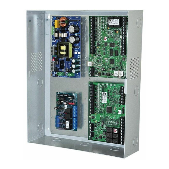
Access & Power Integration
Trove1M1
- Trove1 enclosure with Altronix & Mercury/LenelS2 backplane (TM1)
TM1
- Altronix & Mercury/LenelS2 backplane only
Trove2M2
- Trove2 enclosure with Altronix & Mercury/LenelS2 backplane (TM2)
TM2
- Altronix & Mercury/LenelS2 backplane only
TMV2
- Altronix & Mercury/LenelS2 Door Backplane. Fits Trove2 and Trove3 enclosures
Trove3M3
- Trove3 enclosure with Altronix & Mercury/LenelS2 backplane (TM3)
TM3
- Altronix & Mercury/LenelS2 backplane only
Installation Guide
All registered trademarks are property of their respective owners.
Rev. TMERC101817
Installing Company: _________________________ Service Rep. Name: __________________________________________
Address: _________________________________________________________ Phone #: _________________________
SIGNALING
More than just power.™
Advertisement

Related Manuals for Altronix Trove1M1


Summary of Contents for Altronix Trove1M1
- Page 1 - Trove2 enclosure with Altronix & Mercury/LenelS2 backplane (TM2) - Altronix & Mercury/LenelS2 backplane only TMV2 - Altronix & Mercury/LenelS2 Door Backplane. Fits Trove2 and Trove3 enclosures Trove3M3 - Trove3 enclosure with Altronix & Mercury/LenelS2 backplane (TM3) - Altronix & Mercury/LenelS2 backplane only Installation Guide More than just power.™...
-
Page 2: Specifications
Overview: Altronix Trove1M1, Trove2M2 and Trove3M3 accommodate various combinations of Mercury/LenelS2 boards with or without Altronix power sup- plies and sub-assemblies for access systems. Specifications: • 16 Gauge backplane and enclosure with ample knockouts for convenient access. Trove1M1 TMV2 - Optional Door Backplane Trove1 enclosure with •... - Page 3 Tamper Switch 3. Mount included UL Listed tamper switch(es) (Altronix Model TS112 or equivalent) in desired location, (included) opposite hinge. Slide the tamper switch bracket onto the edge of the enclosure approximately 2” from To Access Control Panel or the right side (Fig.
- Page 4 24VDC @ 1.75A or 3.5A (Output: 5VDC or 12VDC @ 6A) VR6 Installation Instructions Rev. 050517 LINQ2** 12-24VDC @ 100mA max. LINQ2 Installation Instructions Rev. 060514 Altronix Power Supplies/Sub-Assemblies Sub-Assembly Pem Mounting Input Rating Output Rating Refer to AL400ULXB2 115VAC, 60Hz, 3.5A 12VDC @ 4A or 24VDC @ 3A ULXB Installation Instructions Rev.
- Page 5 Altronix Power Supplies/Chargers and/or Sub-Assemblies: 1. Fasten spacers (provided) to pems that match the hole pattern for Altronix Power Supply/Chargers or Altronix Sub-Assembly boards (positions (B) and (C), Fig. 2, pg. 5). Use snap on nylon spacers for the upper two mounting holes in the board.
- Page 6 TM2 Sub-Assembly Position Chart for the Following Models: Altronix Power Supplies/Chargers Altronix Pem Mounting Input Rating Output Rating Refer to AL400ULXB2 115VAC, 60Hz, 3.5A 12VDC @ 4A or 24VDC @ 3A ULXB Installation Instructions Rev. ULXB-020419 AL600ULXB 115VAC, 60Hz, 3.5A 12VDC or 24VDC @ 6A ULXB Installation Instructions Rev.
- Page 7 Installation Instructions for Altronix Power Supplies and/or Sub-Assemblies to TM2: 1. Fasten spacers (provided) to pems that match the hole pattern for Altronix Power Supply/Chargers or Altronix Sub-Assembly boards (Fig. 3, pg. 7). Use snap on nylon spacers for the upper two mounting holes in the board.
- Page 8 Installation Instructions for Mercury/LenelS2 Access Controllers to TM2: 1. Fasten snap on spacers onto metal pems configuration (A) (B) of backplane depending on the access controller (Fig. 4, pg. 8). 2. Position access controller module over corresponding spacers and depress onto snap on spacers (Fig. 4a, pg. 8). 3.
- Page 9 Installation Instructions for Mercury/LenelS2 Access Controllers to TM2: 1. Fasten snap on spacers onto metal pems configuration (A) (B) of backplane depending on the access controller (Fig. 5, pg. 9). 2. Position access controller module over corresponding spacers and depress onto snap on spacers (Fig. 5a, pg. 9). 3.
- Page 10 Installation Instructions for Mercury/LenelS2 Access Controllers to TMV2 (Door Backplane): 1. Fasten snap on spacers onto metal pems configuration (A) (B) of backplane depending on the access controller (Fig. 6, pg. 10). 2. Position access controller module over corresponding spacers and depress onto snap on spacers (Fig. 6a, pg. 10). 3.
- Page 11 TM3 Sub-Assembly Position Chart for the Following Models: Altronix Power Supplies/Chargers Altronix Pem Mounting Input Rating Output Rating Refer to AL400ULXB2 115VAC, 60Hz, 3.5A 12VDC @ 4A or 24VDC @ 3A ULXB Installation Instructions Rev. ULXB-020419 AL600ULXB 115VAC, 60Hz, 3.5A 12VDC or 24VDC @ 6A ULXB Installation Instructions Rev.
- Page 12 Installation Instructions for Altronix Power Supplies and/or Sub-Assemblies to TM3: 1. Fasten spacers (provided) to pems that match the hole pattern for Altronix Power Supply/Chargers or Altronix Sub-Assembly boards (Fig. 7, pg. 12). Use snap on nylon spacers for the upper two mounting holes in the board.
- Page 13 Installation Instructions for Mercury/LenelS2 Access Controllers to TM3: 1. Fasten snap on spacers onto metal pems configuration (A) (B) of backplane depending on the access controller (Fig. 8, pg. 13). 2. Position access controller module over corresponding spacers and depress onto snap on spacers (Fig. 8a, pg. 13). 3.
- Page 14 TM1 Dimensions 16.625” x 12.5” x 0.3125” (422.3mm x 317.5mm x 7.9mm) 12.5” (317.5mm) 0.5” (12.7mm) 0.5” (12.7mm) 6.25” (158.75mm) - 14 - Trove Mercury/LenelS2 Installation Guide...
- Page 15 Trove1M1 Enclosure Dimensions (H x W x D approximate): 18” x 14.5” x 4.625” (457mm x 368mm x 118mm) 14.5” (321.3mm) 7.25” (184.2mm) 1.45” (36.8mm) 1.95” (49.5mm) 4.5” (114.3mm) 13.0” (330.2mm) 1.25” (31.8mm) 1.25” (31.8mm) 1.5” (38.1mm) 1.5” (38.1mm) 0.6” (15.2mm) 0.57”...
- Page 16 TM2 Dimensions 25.375” x 19.375” x 0.3125” (644.5mm x 482.6mm x 7.9mm). 19.375” (492.1mm) 2.2” (55.9mm) 2.2” (55.9mm) 0.156” ( 3.96mm) 1.0” (25.4mm) 1.0” (25.4mm) 7.5” (190.5mm) 7.5” (190.5mm) 9.2” (233.7mm) 9.2” (233.7mm) Trove Mercury/LenelS2 Installation Guide - 16 -...
- Page 17 Trove2M2 Enclosure Dimensions (H x W x D approximate): 27.25” x 21.75” x 6.5” (692.2mm x 552.5mm x 165.1mm) 21.50” (546.1mm) 2.00” (50.8mm) 2.00” (50.8mm) 5.25” (133.35mm) 3.5”(88.9mm) 3.5”(88.9mm) 5.25” (133.35mm) 0.685” (17.4mm) 1.25” Knockouts 0.5625” (14.3mm) (31.8mm) 1.77” 1.125” (28.3mm) (45mm) 2.415”...
- Page 18 TMV2 Door Backplane Dimensions (H x W x D): 23.75” x 18.125” x 0.3125” (603.3mm x 460.3mm x 7.9mm) 18.125” (460.3mm) 13.7” (350mm) 0.156” ( 4mm) 0.45” (11.4mm) 8.7” 8.7” (221mm) (221mm) 11.8” (299.7mm) 13.7” (350mm) - 18 - Trove Mercury/LenelS2 Installation Guide...
- Page 19 TM3 Dimensions 34” x 28” x 0.3125” (863.6mm x 711.2mm x 7.9mm) 28” (711.2mm) 2.5” (63.5mm) 0.156” ( 3.96mm) 1.0” (25.4mm) 1.0” (25.4mm) 13.5” 13.5” (342.9mm) (342.9mm) Trove Mercury/LenelS2 Installation Guide - 19 -...
- Page 20 8.75” (222.3mm) 8.62” (219mm) 8.75” (222.3mm) 2” (50.8mm) Altronix is not responsible for any typographical errors. –––––––––––––––––––––––––––––––––––––––––––––––––––––––––––––––––––––––––––––––––––––––––––––––––––––––––––––––––––––––––––––––––––––––––––––––––––––––– 140 58th Street, Brooklyn, New York 11220 USA | phone: 718-567-8181 | fax: 718-567-9056 web site: www.altronix.com | e-mail: info@altronix.com IITrove Mercury/LenelS2 I24U...