
Related Manuals for Siemens 7SR18 Solkor


Summary of Contents for Siemens 7SR18 Solkor
- Page 1 Reyrolle Protection Devices 7SR18 Solkor Line Differential Relay Energy Management...
- Page 2 Siemens Protection Devices Limited...
- Page 3 Limited. No part of this document shall be reproduced or modified or stored in another form, in any data retrieval system, without the permission of Siemens Protection Devices Limited, nor shall any model or article be reproduced from this document unless Siemens Protection Devices Limited consent.
- Page 4 Protection Devices Limited. No part of this document shall be reproduced or modified or stored in another form, in any data retrieval system, without the permission of Siemens Protection Devices Limited, nor shall any model or article be reproduced from this document unless Siemens Protection Devices Limited consent.
- Page 5 Typographical revisions, amended drawings. 2017/11 Typographical revisions, added data. 2018/07 Amended connection diagrams, additional disposal information Software Revision History 2016/11 2436H80016R4d-1b First Release 2018/07 2436H80016R4i-1c Software maintenance to address production SW upload. Unrestricted ©2018 Siemens Protection Devices Limited Page 2 of 78...
-
Page 6: Table Of Contents
4.1 Auto-Reclose (79) ..........................49 4.1.1 Overview..........................49 4.1.2 Auto Reclose sequences ....................51 4.2 Autoreclose Prot’n Menu ........................52 4.3 Autoreclose Config Menu ......................... 52 4.4 P/F Shots Sub-Menu........................54 Unrestricted ©2018 Siemens Protection Devices Limited Page 3 of 78... - Page 7 6.8 Real Time Clock ..........................77 6.8.1 Time Synchronisation – Data Communication Interface............77 6.8.2 Time Synchronisation – Binary Input .................. 77 6.9 Settings Groups ..........................77 6.10 Password Feature ........................... 78 Unrestricted Page 4 of 78 ©2018 Siemens Protection Devices Limited...
- Page 8 Figure 5.2-1 Logic Diagram: Circuit Breaker Fail Protection (50BF) ..............64 Figure 5.3.1-1 Logic Diagram: CT Supervision Function (60CTS-I) ..............65 Figure 5.3.2-1 Logic Diagram: CT Supervision Function (60CTS) ..............66 Unrestricted ©2018 Siemens Protection Devices Limited Page 5 of 78...
- Page 9 Figure 5.5-1 Logic Diagram: Trip Circuit Supervision Feature (74TCS) .............. 68 Figure 5.5-2 Logic Diagram: Close Circuit Supervision Feature (74CCS)............68 Figure 5.6-1 Functional Diagram for Harmonic Block Feature (81HBL2) ............69 Figure 6.4.7-1Energy Direction Convention ...................... 74 Unrestricted Page 6 of 78 ©2018 Siemens Protection Devices Limited...
- Page 10 The following notational and formatting conventions are used within the remainder of this document: Setting Menu Location MAIN MENU>SUB-MENU Setting: Elem name -Setting Setting value: value Alternatives: [1st] [2nd] [3rd] Unrestricted ©2018 Siemens Protection Devices Limited Page 7 of 78...
-
Page 11: Current Transformer Circuits
Optical power meters should be used to determine the operation or signal level of the device. 1.4 F RONT OVER The front cover provides additional securing of the relay element within the case. The relay cover should be in place during normal operating conditions. Unrestricted Page 8 of 78 ©2018 Siemens Protection Devices Limited... -
Page 12: Table 1.4-1 7Sr18 Ordering Options
67/50, 67/51 Directional Overcurrent 67 G/N Directional Earth Fault Version C - plus Autoreclose Additional Functionality No additional functionality Spare Refer to Technical Manual Standard Version Cover - No Push Buttons Unrestricted ©2018 Siemens Protection Devices Limited Page 9 of 78... -
Page 13: Figure 1.4-1 Functional Diagram Of 7Sr18 Non-Directional Three-Phase And Earth
50 BF 81HBL2 (x2) (x2) NOTE: The use of 74TCS 74CCS Ordering Options some functions are (x3) (x3) mutually exclusive Figure 1.4-1 Functional Diagram of 7SR18 Non-Directional Three-Phase and Earth Unrestricted Page 10 of 78 ©2018 Siemens Protection Devices Limited... -
Page 14: Figure 1.4-2 Connections Diagram For 7Sr18 Non-Directional Relay (3Bi And 5Bo)
7SR18 Description Of Operation Figure 1.4-2 Connections Diagram for 7SR18 Non-Directional Relay (3BI and 5BO) Unrestricted ©2018 Siemens Protection Devices Limited Page 11 of 78... -
Page 15: Figure 1.4-3 Connections Diagram For 7Sr18 Non-Directional Relay (6Bi And 8Bo)
7SR18 Description Of Operation Figure 1.4-3 Connections Diagram for 7SR18 Non-Directional Relay (6BI and 8BO) Unrestricted Page 12 of 78 ©2018 Siemens Protection Devices Limited... -
Page 16: Figure 1.4-4 Functional Diagram Of 7Sr18 Directional Three-Phase And Earth
50 BF 81HBL2 (x4) (x4) 74TCS (x3) 74CCS (x3) NOTE: The use of Ordering Options some functions are mutually exclusive Figure 1.4-4 Functional Diagram of 7SR18 Directional Three-Phase and Earth Unrestricted ©2018 Siemens Protection Devices Limited Page 13 of 78... -
Page 17: Figure 1.4-5 Connections Diagram For 7Sr18 Directional Relay (3Bi And 5Bo)
7SR18 Description Of Operation Figure 1.4-5 Connections Diagram for 7SR18 Directional Relay (3BI and 5BO) Unrestricted Page 14 of 78 ©2018 Siemens Protection Devices Limited... -
Page 18: Figure 1.4-6 Connections Diagram For 7Sr18 Directional Relay (6Bi And 8Bo)
7SR18 Description Of Operation Figure 1.4-6 Connections Diagram for 7SR18 Directional Relay (6BI and 8BO) Unrestricted ©2018 Siemens Protection Devices Limited Page 15 of 78... -
Page 19: Section 2: Hardware Description
4) Power Supply 3 x Binary Input (BI) + RS485 5) Protection Signalling module 6) Communications Module (2x Electrical Ethernet for IEC 61850) or (2x Optical Ethernet for IEC 61850) (Option) Unrestricted Page 16 of 78 ©2018 Siemens Protection Devices Limited... -
Page 20: Case
Located at the top rear of the case is a screw clamp earthing point, this must be connected to terminal B28 and directly to the main panel earth. This connection point is indicated by the following symbol. Figure 2.2-3 Earth connection Symbol Unrestricted ©2018 Siemens Protection Devices Limited Page 17 of 78... -
Page 21: Front Cover
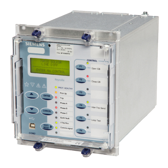
As standard the relay is supplied with a transparent front cover. The front cover is used to secure the relay assembly in the case. Figure 2.3-1 Relay with transparent cover Unrestricted Page 18 of 78 ©2018 Siemens Protection Devices Limited... -
Page 22: Power Supply Unit (Psu)
The fascia is an integral part of the relay. Handles are located at each side of the relay which allow it to be withdrawn from the relay case. The relay should not be carried by these handles. Unrestricted ©2018 Siemens Protection Devices Limited Page 19 of 78... -
Page 23: Figure 2.5-2 Close Up Of Typical Relay Label
A ‘template’ is available in ‘Reydisp Evolution/Help/Open Relay LED Template’ to allow users to create and print customised labels. For information and safety reasons the following symbols are displayed on the fascia panel: - Unrestricted Page 20 of 78 ©2018 Siemens Protection Devices Limited... -
Page 24: Figure 2.5-3 Typical Relay Identifier Lcd Text
Alternatively configuration/settings files can be loaded into the relay using ‘Reydisp’. When the System Config>Setting Dependencies is ENABLED, only the functions that are enabled will appear in the menu structure. Unrestricted ©2018 Siemens Protection Devices Limited Page 21 of 78... -
Page 25: Figure 2.5-4 Led Indication Label
The status of hand reset LEDs is maintained by a back-up storage capacitor in the event of an interruption to the d.c. supply voltage. Figure 2.5-4 LED Indication Label Unrestricted Page 22 of 78 ©2018 Siemens Protection Devices Limited... -
Page 26: Current Inputs
INPUT CONFIG > BINARY INPUT CONFIG menu. Unrestricted ©2018 Siemens Protection Devices Limited Page 23 of 78... -
Page 27: Binary Outputs (Output Contacts)
OUTPUT CONFIG>BINARY OUTPUT CONFIG>Pickup Outputs setting. Notes on Pulsed Outputs When operated, the output will reset after a user configurable time of up to 60 seconds regardless of the initiating condition. Unrestricted Page 24 of 78 ©2018 Siemens Protection Devices Limited... -
Page 28: Virtual Input/Output Connections
- using the INPUT CONFIG > INPUT MATRIX menu. Virtual input/outputs can also be used as data items in equations. The status of the virtual inputs and outputs is volatile i.e. not stored during power loss. Unrestricted ©2018 Siemens Protection Devices Limited Page 25 of 78... -
Page 29: Self Monitoring
SYSTEM CONFIG>Unexpected Restart Blocking setting to remove itself from service. In this case the Relay will display a typical error message such as: - Figure 2.11-2 Unexpected Restarts Lockout Text Unrestricted Page 26 of 78 ©2018 Siemens Protection Devices Limited... -
Page 30: Protection Healthy/Defective
If the relay is withdrawn from the case, the case shorting contact will make across the normally closed contacts to provide and external alarm. Unrestricted ©2018 Siemens Protection Devices Limited Page 27 of 78... -
Page 31: Section 3: Protection Functions
Bias Slope Limit setting defines the border between the 1 and 2 bias slopes. The 87L 2 Bias Slope setting is used to modify the sensitivity of the differential algorithm at higher current levels. Unrestricted Page 28 of 78 ©2018 Siemens Protection Devices Limited... -
Page 32: Figure 3.1.1-2 Biased Differential Characteristic (Offset Enabled - Default)
Prot Comms Fail Inhibit 87L-n Pickup General Pickup Operate Phase Multiplier Reversal Pickup Local Operate 87L-n Delay Pickup 87L-n Operate Phase Multiplier Reversal Remote Figure 3.1.1-3 Logic Diagram: Biased Current Differential Protection Unrestricted ©2018 Siemens Protection Devices Limited Page 29 of 78... -
Page 33: Differential Highset (87Hs-N)
Operation of the highset differential elements can be inhibited from: - Inhibit 87HS A binary or virtual input. User Inhibit Reylogic (graphical logic). Figure 3.1.2-2 Logic Diagram: Differential High Set Current Protection Unrestricted Page 30 of 78 ©2018 Siemens Protection Devices Limited... -
Page 34: Protection Communication Signalling Supervision
Inter-trip channels are especially useful to apply Start, Inhibit, Lockout logic to a Feeder Autoreclose scheme to allow sequenced closing of the circuit-breakers. Unrestricted ©2018 Siemens Protection Devices Limited Page 31 of 78... -
Page 35: Current Protection: Phase Overcurrent (67, 50, 51)
This prevents mal-operation under fuse failure/MCB tripped conditions where noise voltages can be present. Unrestricted Page 32 of 78 ©2018 Siemens Protection Devices Limited... -
Page 36: Instantaneous Overcurrent Protection (50)
When ‘delayed’ trips only are allowed in the auto-reclose sequence (79 P/F Prot’n Trip n = Delayed). 50-n Inrush Action: Block Operation of the inrush current detector function. 50-n VTS Action: Inhibit Operation of the VT Supervision function. Unrestricted ©2018 Siemens Protection Devices Limited Page 33 of 78... -
Page 37: Figure 3.3.2-1 Logic Diagram: Instantaneous Over-Current Element
7SR18 Description Of Operation Figure 3.3.2-1 Logic Diagram: Instantaneous Over-current Element Unrestricted Page 34 of 78 ©2018 Siemens Protection Devices Limited... -
Page 38: Time Delayed Overcurrent Protection (51)
(79 P/F Prot’n Trip n = Delayed). Activation of the cold load settings. 50-n Inrush Action: Block Operation of the inrush current detector function. 51-n VTSAction: Inhibit Operation of the VT Supervision function. Unrestricted ©2018 Siemens Protection Devices Limited Page 35 of 78... -
Page 39: Figure 3.3.3-1 Logic Diagram: Time Delayed Overcurrent Element
7SR18 Description Of Operation Figure 3.3.3-1 Logic Diagram: Time Delayed Overcurrent Element Unrestricted Page 36 of 78 ©2018 Siemens Protection Devices Limited... -
Page 40: Voltage Controlled Overcurrent (51V)
Current Element Control Voltage The Voltage Controlled Overcurrent function (51V) can be inhibited from: VCO VTSAction: Inhibit Operation of the VT Supervision function. Figure 3.3.4-1 Logic Diagram: Voltage Controlled Overcurrent Element Unrestricted ©2018 Siemens Protection Devices Limited Page 37 of 78... -
Page 41: Current Protection: Derived Earth Fault (67N, 51N, 50N)
This prevents mal-operation under fuse failure/MCB tripped conditions where noise voltages can be present. Figure 3.4.1-1 Logic Diagram: Derived Directional Earth Fault Protection Unrestricted Page 38 of 78 ©2018 Siemens Protection Devices Limited... -
Page 42: Instantaneous Derived Earth Fault Protection (50N)
(79 E/F Prot’n Trip n = Delayed). 50-n Inrush Action: Block Operation of the inrush current detector function. 50N-n VTSAction: Inhibit Operation of the VT Supervision function Figure 3.4.2-1 Logic Diagram: Derived Instantaneous Earth Fault Element Unrestricted ©2018 Siemens Protection Devices Limited Page 39 of 78... -
Page 43: Time Delayed Derived Earth Fault Protection (51N)
Operation of the time delayed earth fault elements can be inhibited from: - Inhibit 51N-n A binary or virtual input. 50-n Inrush Action: Block Operation of the inrush current detector function. Figure 3.4.3-1 Logic Diagram: Derived Time Delayed Earth Fault Element Unrestricted Page 40 of 78 ©2018 Siemens Protection Devices Limited... -
Page 44: Current Protection: Measured Earth Fault (67G, 51G, 50G)
Operation of protection elements set as directional will be inhibited. This prevents mal-operation under fuse failure/MCB tripped conditions where noise voltages can be present. Figure 3.5.1-1 Logic Diagram: Measured Earth Fault Protection Unrestricted ©2018 Siemens Protection Devices Limited Page 41 of 78... -
Page 45: Instantaneous Measured Earth Fault Protection (50G)
(79 E/F Prot’n Trip n = Delayed). 50-n Inrush Action: Block Operation of the inrush current detector function. 50G-n VTSAction: Inhibit Operation of the VT Supervision function Figure 3.5.2-1 Logic Diagram: Measured Instantaneous Earth-fault Element Unrestricted Page 42 of 78 ©2018 Siemens Protection Devices Limited... -
Page 46: Time Delayed Measured Earth Fault Protection (51G)
50-n Inrush Action: Block Operation of the inrush current detector function. 50N-n VTSAction: Inhibit Operation of the VT Supervision function Figure 3.5.3-1 Logic Diagram: Measured Time Delayed Earth Fault Element (51G) Unrestricted ©2018 Siemens Protection Devices Limited Page 43 of 78... -
Page 47: Current Protection: Cold Load (51C)
Cold load trips use the same binary output(s) as the associated 51-n element. Operation of the cold load element can be inhibited from: Inhibit Cold Load A binary or virtual input. Figure 3.6-1 Logic Diagram: Cold Load Settings (51c) Unrestricted Page 44 of 78 ©2018 Siemens Protection Devices Limited... -
Page 48: Current Protection: Negative Phase Sequence Overcurrent - (46Nps)
Operation of the negative phase sequence overcurrent elements can be inhibited from: Inhibit 46IT A binary or virtual input. Inhibit 46DT A binary or virtual input. Figure 3.7-1 Logic Diagram: Negative Phase Sequence Overcurrent (46NPS) Unrestricted ©2018 Siemens Protection Devices Limited Page 45 of 78... -
Page 49: Current Protection: Under-Current (37 & 37G)
A binary or virtual input. 37U/I Guard Setting 0.05, 0.1..5xIn Figure 3.8-1 Logic Diagram: Phase Current Inputs Undercurrent Detector (37) & < Figure 3.8-2 Logic Diagram: Earth Current Inputs Undercurrent Detector (37G) Unrestricted Page 46 of 78 ©2018 Siemens Protection Devices Limited... -
Page 50: Current Protection: Thermal Overload (49)
The thermal state may be reset from the fascia or externally via a binary input. Thermal overload protection can be inhibited from: Inhibit 49 A binary or virtual input. Unrestricted ©2018 Siemens Protection Devices Limited Page 47 of 78... -
Page 51: Current Protection: Line Check 50Lc, 50G Lc
Line Check binary input is energised. Figure 3.10-1 Logic Diagram: 50G Line Check Elements (50G LC) Figure 3.10-2 Logic Diagram: 50 Line Check Elements (50LC) Unrestricted Page 48 of 78 ©2018 Siemens Protection Devices Limited... -
Page 52: Section 4: Control & Logic Functions
Successful Close output issued. A single, common Reclaim time is used ( Reclaim Timer). When an auto-reclose sequence does not result in a successful reclosure the relay goes to the lockout state. Unrestricted ©2018 Siemens Protection Devices Limited Page 49 of 78... - Page 53 79 In Progress 79 AR Close CB 79 Successful AR 79 Lockout 79 Close Onto Fault 79 CB Fail to Close 79 Trip _Reclose 79 Trip _Lockout 79 Block Extern Unrestricted Page 50 of 78 ©2018 Siemens Protection Devices Limited...
-
Page 54: Auto Reclose Sequences
The CB close output relay is energised after the dead time has elapsed. Trip (Inst) Trip (Inst) Trip (Inst) Trip (Delayed) Dead Time Dead Time Dead Time Dead Time Typical Sequence with 3 Instantaneous and 1 Delayed trip Figure 4.1.2-1 Unrestricted ©2018 Siemens Protection Devices Limited Page 51 of 78... -
Page 55: Autoreclose Prot'n Menu
Selects whether whilst Cold Load is active the relay will perform only Delayed Trips. When set to Off, both Inst and Delayed elements will be active. This setting does not block Autoreclose for Cold Load trips. Unrestricted Page 52 of 78 ©2018 Siemens Protection Devices Limited... - Page 56 The Lockout condition has a delayed drop-off time of 2s. The Lockout condition cannot be reset if there is an active lockout input. Note: If the ‘CB Total Trip Count’ or the ‘CB Frequent Ops Count’ target is reached the relay will do one delayed tip and lockout. Unrestricted ©2018 Siemens Protection Devices Limited Page 53 of 78...
-
Page 57: P/F Shots Sub-Menu
Instantaneous protection Elements are externally inhibited for system operating reasons - sequences are truncated. E/F Shots Sub-Menu This menu allows the Earth Fault trip/reclose sequence to be parameterized:- As above but E/F settings. Unrestricted Page 54 of 78 ©2018 Siemens Protection Devices Limited... -
Page 58: Extern Shots Sub-Menu
External AutoReclose sequence can be applied for this purpose. By setting-up internal Quick Logic equation(s) the user can define and set what should occur when any one of these other elements operates. Unrestricted ©2018 Siemens Protection Devices Limited Page 55 of 78... -
Page 59: Figure 4.6-1 Basic Auto-Reclose Sequence Diagram
7SR18 Description Of Operation Basic Auto-Reclose Sequence Diagram Figure 4.6-1 Unrestricted Page 56 of 78 ©2018 Siemens Protection Devices Limited... -
Page 60: Manual Cb Control
Reset operation can be useful, however, as it allows a close or trip sequence to be aborted by dropping off the binary input signal. Unrestricted ©2018 Siemens Protection Devices Limited Page 57 of 78... -
Page 61: Circuit Breaker
CB Travel Alarm setting. An instantaneous CB Alarm is given for a 1/1 state – i.e. where the CB indicates it is both Open and Closed at the same time. Unrestricted Page 58 of 78 ©2018 Siemens Protection Devices Limited... -
Page 62: Figure 4.8-1 Logic Diagram: Circuit Breaker Status
This allows for the internal delays caused by the relay – especially the delay before a binary input operates – to be subtracted from the measured CB trip time. This gives a more accurate measurement of the time it took for the CB to actually trip. Unrestricted ©2018 Siemens Protection Devices Limited Page 59 of 78... -
Page 63: Quick Logic
En Counter Reset Mode = Multi Shot: The En Counter Reset Time is started each time the counter is incremented. Where En Counter Reset Time elapses without further count increments the count value is reset to zero. Unrestricted Page 60 of 78 ©2018 Siemens Protection Devices Limited... -
Page 64: Figure 4.9-1 Sequence Diagram: Quick Logic Pu/Do Timers (Counter Reset Mode Off)
The output of En is assigned in the OUTPUT CONFIG>OUTPUT MATRIX menu where it can be programmed to any binary output (O), LED (L) or Virtual Input/Output (V) combination. Protection functions can be used in Quick Logic by mapping them to a Virtual Input / Output. Unrestricted ©2018 Siemens Protection Devices Limited Page 61 of 78... -
Page 65: Section 5: Supervision Functions
50BF-n Delay will be by-passed and the output given immediately. Operation of the CB Fail elements can be inhibited from: Inhibit 50BF A binary or virtual input. Figure 5.1-1 Logic Diagram: Circuit Breaker Fail Protection (50BF) Unrestricted Page 62 of 78 ©2018 Siemens Protection Devices Limited... -
Page 66: Vt Supervision (60Vts)
Voltage is restored to a healthy state i.e. above VPPS setting while NPS voltage is below VNPS setting. Ext Reset 60VTS A binary or virtual input, or function key and a VT failure condition no longer exists. Inhibit 60VTS A binary or virtual input. Unrestricted ©2018 Siemens Protection Devices Limited Page 63 of 78... -
Page 67: Figure 5.2-1 Logic Diagram: Circuit Breaker Fail Protection (50Bf)
7SR18 Description Of Operation Figure 5.2-1 Logic Diagram: Circuit Breaker Fail Protection (50BF) Unrestricted Page 64 of 78 ©2018 Siemens Protection Devices Limited... -
Page 68: Ct Supervision (60Cts-I & Cts)
60CTS-I Element Enabled Disabled & Inhibit 60CTS-I 60CTS-I Delay 60CTS I-I & 60CTS-I Operated < Any 2 phases but not all 3 Figure 5.3.1-1 Logic Diagram: CT Supervision Function (60CTS-I) Unrestricted ©2018 Siemens Protection Devices Limited Page 65 of 78... -
Page 69: 60Cts
60CTS Delay then a CT failure output (60CTS Operated) is given. Operation of the CT supervision elements can be inhibited from: Inhibit 60CTS A binary or virtual input. Figure 5.3.2-1 Logic Diagram: CT Supervision Function (60CTS) Unrestricted Page 66 of 78 ©2018 Siemens Protection Devices Limited... -
Page 70: Broken Conductor (46Bc)
Inhibit 46BC A binary or virtual input. 46BC U/C Guard A minimum load current. 46BC U/C Guard Setting (0.05, 0.1... 5x In) Figure 5.4-1 Logic Diagram: Broken Conductor Function (46BC) Unrestricted ©2018 Siemens Protection Devices Limited Page 67 of 78... -
Page 71: Trip / Close Circuit Supervision (74Tcs & 74Ccs)
The use of one or two binary inputs mapped to the same Trip Circuit Supervision element (e.g. 74TCS-n) allows the user to realise several alternative monitoring schemes. Figure 5.5-1 Logic Diagram: Trip Circuit Supervision Feature (74TCS) Figure 5.5-2 Logic Diagram: Close Circuit Supervision Feature (74CCS) Unrestricted Page 68 of 78 ©2018 Siemens Protection Devices Limited... -
Page 72: 2Nd Harmonic Block/Inrush Restraint (81Hbl2) Phase Elements Only
Enabled > 1 81HBL2 Disabled 81HBL2 Setting & Inhibit 81HBL2 81HBL2 Bias > L1 81HBL2 > L2 81HBL2 > L3 81HBL2 Figure 5.6-1 Functional Diagram for Harmonic Block Feature (81HBL2) Unrestricted ©2018 Siemens Protection Devices Limited Page 69 of 78... -
Page 73: Section 6: Other Features
When communication is lost on the Channel 2 Ethernet port this point becomes true. For further details refer to the following publications: Model Implementation Conformance Statement (MICS) Protocol Implementation Conformance Statement (PICS) Protocol Implementation Extra Information for Testing (PIXIT) Unrestricted Page 70 of 78 ©2018 Siemens Protection Devices Limited... -
Page 74: Maintenance
CB contacts separation when an arc is formed, Separation Time, and the CB Clearance time. The I t value can also triggered and reset from a binary input or command. 6.3.4 Start Count Refer to 2.11 Self Monitoring. Unrestricted ©2018 Siemens Protection Devices Limited Page 71 of 78... -
Page 75: Data Storage
Triggering of waveform storage is configured from the ‘Settings > DATA STORAGE > WAVEFORM STORAGE’ menu. Triggering is initiated from operation of any of the selected protection or control elements. Unrestricted Page 72 of 78 ©2018 Siemens Protection Devices Limited... -
Page 76: Fault Records
The 'A' symbol at the top-right position of the LCD indicates that new Events, Waveform Records or Fault Records are currently being held in volatile RAM and the archiving, to non-volatile flash disk storage, is being temporarily blocked. Unrestricted ©2018 Siemens Protection Devices Limited Page 73 of 78... -
Page 77: Energy Storage
The value is stored in the range 0-999999 which continues from zero automatically when 999999 is reached. Unrestricted Page 74 of 78 ©2018 Siemens Protection Devices Limited... -
Page 78: Metering
Config/Favourite Meters Timer menu. The energy storage meters can be reset from a binary input and have a user selectable setting for their measurement in the Data Storage/Energy storage menu. Unrestricted ©2018 Siemens Protection Devices Limited Page 75 of 78... -
Page 79: Operating Mode
Note also that switching a protection function IN / OUT via the Control Menu will not change that function’s ENABLED / DISABLED setting. The Control Menu selection will over-ride the setting, however. Control Mode commands are password protected using the Control Password function – see Section 6.10. Unrestricted Page 76 of 78 ©2018 Siemens Protection Devices Limited... -
Page 80: Real Time Clock
(Select Grp Mode: Level triggered) or latches into the selected group after energisation of the input (Select Grp Mode: Edge triggered). Settings are stored in non-volatile memory. Unrestricted ©2018 Siemens Protection Devices Limited Page 77 of 78... -
Page 81: Password Feature
The password validation screen also displays a numerical code. If the password is lost or forgotten, this code should be communicated to Siemens Protection Devices Ltd. and the password can be retrieved. Unrestricted Page 78 of 78 ©2018 Siemens Protection Devices Limited... - Page 82 Protection Devices Limited. No part of this document shall be reproduced or modified or stored in another form, in any data retrieval system, without the permission of Siemens Protection Devices Limited, nor shall any model or article be reproduced from this document unless Siemens Protection Devices Limited consent.
- Page 83 Typographical revisions, drawing amendments 2017/11 Typographical revisions, drawing amendments 2018/07 Amended connection diagrams, additional disposal information Software Revision History 2016/11 2436H80016R4d-1b First Release 2018/07 2436H80016R4i-1c Software maintenance to address production SW upload. Unrestricted Page 2 of 12 © 2015 Siemens Protection Devices Limited...
- Page 84 Figure 3.1.1-1 USB connection to a PC ......................8 Figure 3.1.2-1 Standard rear RS485 connection to a PC ..................9 Figure 3.1.3-1 EN100 Ethernet Module ......................9 Figure 3.1.7-1 PC Comm Port Selection ......................11 Unrestricted © 2015 Siemens Protection Devices Limited Page 3 of 12...
-
Page 85: Relay Menus And Display
To change the contrast on the LCD insert a flat nosed screwdriver into the screwhead below the contrast symbol, turning the screwhead left or right decreases and increases the contrast of the LCD. Figure 1.1-2 Contrast symbol Unrestricted Page 4 of 12 © 2015 Siemens Protection Devices Limited... - Page 86 7SR18 Configuration Guide Figure 1.1-3 Relay Fascia (Please note fascia may differ from illustration) Unrestricted © 2015 Siemens Protection Devices Limited Page 5 of 1...
-
Page 87: Section 2: Operation Guide
LEDs will momentarily light up to indicate their correct operation. It is also moves the cursor right ► when navigating through menus and settings. Unrestricted Page 6 of 12 © 2015 Siemens Protection Devices Limited... - Page 88 BINARY INPUT CONFIG GENERAL ALARMS OUTPUT MATRIX OUTPUT CONFIG BINARY OUTPUT CONFIG LED CONFIG PICKUP CONFIG CB COUNTERS CB MAINTENANCE I^2T CB WEAR DATA STORAGE COMMUNICATIONS Figure 2.1-2 Typical Menu Structure Unrestricted © 2015 Siemens Protection Devices Limited Page 7 of 1...
-
Page 89: Section 3: Configuring The Relay Using Reydisp Evolution
Interface cable and converters are required depending which port is being used. 3.1.1 Front USB connection To connect your pc locally via the front USB port. Figure 3.1.1-1 USB connection to a PC Unrestricted Page 8 of 12 © 2015 Siemens Protection Devices Limited... -
Page 90: Standard Rear Rs485 Connection
Connections are made on the rear underside of the relay either RJ45 sockets (electrical) or Duplex LC (fibre optic) connectors depending on the option ordered. Figure 3.1.3-1 EN100 Ethernet Module Unrestricted © 2015 Siemens Protection Devices Limited Page 9 of 1... -
Page 91: Configuring Relay Data Communication
1 & 254 or 2 & 253 or 3 & 252... etc. Setting name Range Default Notes Different address could 1 – 254 Protection Address signify Local or Remote relay designation. Unrestricted Page 10 of 12 © 2015 Siemens Protection Devices Limited... -
Page 92: Optional Rear En100 Ethernet Module (Com3)
Relay > Set Address > Device Map. The relay can now be configured using the Reydisp Evolution software. Please refer to the Reydisp Evolution Manual for further guidance. Unrestricted © 2015 Siemens Protection Devices Limited Page 11 of... - Page 93 7SR18 Configuration Guide Unrestricted Page 12 of 12 © 2015 Siemens Protection Devices Limited...
- Page 94 Unrestricted The copyright and other intellectual property rights in this document, and in any model or article produced from it (and including any registered or unregistered design rights) are the property of Siemens Protection Devices Limited. No part of this document shall be reproduced or modified or stored in another form, in any data retrieval system, without the permission of Siemens Protection Devices Limited, nor shall any model or article be reproduced from this document unless Siemens Protection Devices Limited consent.
- Page 95 Typographical revisions, drawing amendments. 2017/11 Typographical revisions, added data. 2018/07 Revised data Comms drawings, additional disposal information Software Revision History 2016/11 2436H80016R4d-1b First Release 2018/07 2436H80016R4i-1c Software maintenance to address production SW upload. Unrestricted Page 2 of 24 ©2018 Siemens Protection Devices Limited...
- Page 96 Figure 6.3-2 Ethernet connection for IEC 61850 (ring connection) ..............21 Figure 6.4.1-1RSTP Ethernet Network Ring configuration ................. 22 Figure 6.4.2-1PRP Ethernet Network Configuration ..................23 Figure 6.4.3-1HSR Ethernet Network Ring Configuration .................. 24 Unrestricted ©2018 Siemens Protection Devices Limited Page 3 of 2...
- Page 97 7SR18 Installation Guide List of Tables Table 1: EN100 Redundancy availability ......................22 Unrestricted Page 4 of 24 ©2018 Siemens Protection Devices Limited...
-
Page 98: Unpacking, Storage And Handling
Siemens Protection Devices Limited, and the nearest Siemens agent. When not required for immediate use, Relays should be stored in their original packaging. The place of storage should be dry and free from dust. It should also not exceed the storage temperature and humidity limits of the Relay;... -
Page 99: Ancillary Equipment
When disposing of or transferring a mobile storage device, Siemens strongly recommends physically destroying it or completely deleting data from the mobile storage device by using a commercially available computer data erasing software. -
Page 100: Section 2: Equipment Operating Conditions
Front Cover The front cover provides additional securing of the relay element within the case. The relay cover should be in place during normal operating conditions. Unrestricted ©2018 Siemens Protection Devices Limited Page 7 of... -
Page 101: Section 3: Dimensions And Panel Fixings
The following drawing which is available from the website gives panel cut-out and mounting details. Figure 3.1-1 Overall Dimensions and Panel Drilling for Size E6 Epsilon Case Hardware Model Net Weight Kg 7SR1811 4.26 kg 7SR1812 4.26 kg 7SR1813 4.26 kg 7SR1814 4.26 kg Unrestricted Page 8 of 24 ©2018 Siemens Protection Devices Limited... -
Page 102: Fixings
Typical rear terminal block fixing kit (1kit per terminal block fitted to relay) consists of the following: - 28 off M4, 8 mm Screws 28 off M4 Lock Washer Relay rear retaining screw: - 1 off M3x8 mm Screw Unrestricted ©2018 Siemens Protection Devices Limited Page 9 of... -
Page 103: Section 4: Rear Terminal Drawings
2) RS485 (Block ”B” Terms 14, 16, 18, 20) connection to this communication facility is by screened, twisted pair cable. On site when wiring other facilities ensure that these terminals are not obscured by other wiring runs. Cable should be RS485 compliant. Unrestricted Page 10 of 24 ©2018 Siemens Protection Devices Limited... - Page 104 7SR18 Installation Guide Figure 4.1-2 E6 Case Terminal Arrangement viewed from rear (Typical) Unrestricted ©2018 Siemens Protection Devices Limited Page 11 of 24...
-
Page 105: Section 5: Connection/Wiring/Diagrams
7SR18 Installation Guide Section 5: Connection/Wiring/Diagrams Wiring Diagram: 7SR18 Relay with 3BI & 5BO Figure 5.1-1 Connection Diagram for Non-Directional Relay (3BI 5BO) Unrestricted Page 12 of 24 ©2018 Siemens Protection Devices Limited... -
Page 106: Wiring Diagram: 7Sr18 Relay With 6Bi & 8Bo
7SR18 Installation Guide Wiring Diagram: 7SR18 Relay with 6BI & 8BO Figure 5.2-1 Connection Diagram for Non-Directional Relay (6BI 8BO) Unrestricted ©2018 Siemens Protection Devices Limited Page 13 of 24... -
Page 107: Wiring Diagram: 7Sr18 Relay With 3Bi & 5Bo
7SR18 Installation Guide Wiring Diagram: 7SR18 Relay with 3BI & 5BO Figure 5.3-1 Connection Diagram for Directional Relay (3BI 5BO) Unrestricted Page 14 of 24 ©2018 Siemens Protection Devices Limited... -
Page 108: Wiring Diagram: 7Sr18 Relay With 6Bi & 8Bo
7SR18 Installation Guide Wiring Diagram: 7SR18 Relay with 6BI & 8BO Figure 5.4-1 Connection Diagram for Directional Relay (6BI 8BO) Unrestricted ©2018 Siemens Protection Devices Limited Page 15 of 24... -
Page 109: Typical Current Transformer Configurations
Restricted E/F Ia, Ib, Ic 50/51 - Phase Overcurrent 50N/51N - Derived E/F CT/VT CONFIG: Phase Current Input Selects 1 or 5A Phase CT Ratio CT ratio for primary meters Unrestricted Page 16 of 24 ©2018 Siemens Protection Devices Limited... - Page 110 50N/51N - Derived E/F 50G/51G - CT/VT CONFIG: Measured E/F Phase Current Input Phase CT Ratio Earth Current Selects 1 or 5A Input CT ratio for Earth CT Ratio primary meters Unrestricted ©2018 Siemens Protection Devices Limited Page 17 of 24...
- Page 111 7SR18 Installation Guide Ia, Ib, Ic Phase Overcurrent Derived E/F Measured CT/VT CONFIG: Standby E/F Phase Current Input Phase CT Ratio Selects 1 or 5A CT ratio for primary meters Unrestricted Page 18 of 24 ©2018 Siemens Protection Devices Limited...
-
Page 112: Voltage Transformer Configurations
Phase – Phase Calculated No ZPS available Vab, Vbc, 3Vo 67 & 67N & 67G 47, 59N, 27/59 & 81 Phase – Neutral Calculated Phase – Phase Phase Vca Calculated Unrestricted ©2018 Siemens Protection Devices Limited Page 19 of 24... -
Page 113: Section 6: Data Comms Connections
The RS485 data communications link with a particular relay will be broken if the relay element is withdrawn from the case, all other relays will still communicate. Figure 6.1-1 RS485 Data Comms Connections Between Relays Unrestricted Page 20 of 24 ©2018 Siemens Protection Devices Limited... -
Page 114: Protection Signalling Communication Connection
62.5/125 µm fibre optic Ch 2 with Duplex LC connectors or RJ45 electrical connectors Figure 6.3-1 Ethernet connection for IEC 61850 (star connection) Figure 6.3-2 Ethernet connection for IEC 61850 (ring connection) Unrestricted ©2018 Siemens Protection Devices Limited Page 21 of... -
Page 115: Ethernet Network Redundancy Iec 61850
RSTP need to be enabled on the device within Reydisp Manager (See Reydisp Manager userguide). Network rings with up to 30 devices is possible. Figure 6.4.1-1 RSTP Ethernet Network Ring configuration Unrestricted Page 22 of 24 ©2018 Siemens Protection Devices Limited... -
Page 116: Prp - Parallel Redundancy Protocol
No reconfiguration time is necessary for the network, as is the case for RSTP. PRP need to be enabled on the device within Reydisp Manager (See Reydisp Manager userguide). Figure 6.4.2-1 PRP Ethernet Network Configuration Unrestricted ©2018 Siemens Protection Devices Limited Page 23 of... -
Page 117: Hsr - High Availability Seamless Redundancy Protocol
HSR needs to be enabled on the device within Reydisp Manager (See Reydisp Manager user guide). Network rings with up to 50 devices is possible. Figure 6.4.3-1 HSR Ethernet Network Ring Configuration Unrestricted Page 24 of 24 ©2018 Siemens Protection Devices Limited... - Page 118 Protection Devices Limited. No part of this document shall be reproduced or modified or stored in another form, in any data retrieval system, without the permission of Siemens Protection Devices Limited, nor shall any model or article be reproduced from this document unless Siemens Protection Devices Limited consent.
- Page 119 2018/02 Typographical revisions, drawing amendments, added data. 2018/07 Amended connection diagrams, additional disposal information Software Revision History 2016/11 2436H80016R4d-1b First Release 2018/07 2436H80016R4i-1c Software maintenance to address production SW upload. Unrestricted Page 2 of 44 ©2018 Siemens Protection Devices Limited...
- Page 120 2.6 50N Instantaneous Derived Earth Fault .................... 25 2.6.1 Reference .......................... 25 2.6.2 Operate and Reset Level ....................25 2.6.3 Operate and Reset Time ....................25 2.7 51 Time Delayed Overcurrent ......................26 Unrestricted ©2018 Siemens Protection Devices Limited Page 3 of 4...
- Page 121 ANSI IDMTL Operate Curves (Time Multiplier = 1) ..........29 Figure 2.7.3-3 ANSI Reset Curves (Time Multiplier = 1) ..............30 Figure 2.7.3-4 IEC Reset Curves (Time Multiplier = 1) ..............31 Unrestricted Page 4 of 44 ©2018 Siemens Protection Devices Limited...
-
Page 122: Section 1: Common Functions
See appropriate case outline and panel drilling drawing, as specified in Diagrams and Parameters of the Installation section, for complete dimensional specifications. 1.1.5 Weights Parameter Value (Typical) 7SR1811 4.26 kg 7SR1812 4.26 kg Net weight 7SR1813 4.26 kg 7SR1814 4.26 kg Unrestricted ©2018 Siemens Protection Devices Limited Page 5 of 4... -
Page 123: Energising Quantities
BO, all LEDs, LCD on PROT HEALTHY LED, BO 1 19.30 19.91 20.24 20.64 23.80 25.07 on, LCD on PROT HEALTHY LED, BO 1 17.20 17.82 18.17 18.48 21.20 22.31 on, LCD off Unrestricted Page 6 of 44 ©2018 Siemens Protection Devices Limited... -
Page 124: Ac Analogue Current
1 cycle 700 A 2500 A 1.2.3 AC Analogue Voltage Attribute Nominal Operating Range 40 to 160 Vrms 0 to 200 Vrms 50, 60Hz 47.5 to 52.5Hz and 57 to 63Hz Unrestricted ©2018 Siemens Protection Devices Limited Page 7 of 4... -
Page 125: Binary (Digital) Outputs
To achieve immunity from AC interference, a BI pick-up delay of typically one-cycle can be applied. Unrestricted Page 8 of 44 ©2018 Siemens Protection Devices Limited... -
Page 126: Functional Performance
Real Time Clock 1.3.2.1 Internal Clock The specification below applies only while no external synchronisation signal (e.g. 60870-5-103) is being received. Attribute Value ± 3.5 p.p.m Accuracy (-10 C to +55 Unrestricted ©2018 Siemens Protection Devices Limited Page 9 of 4... -
Page 127: Data Communication Interfaces
Attribute Value Physical layer Electrical Connectors RJ45 100BaseF in acc. With IEEE802.3 Transmission Speed 100 MBits/s Test Voltage (with regard to socket) 500 VAC 50 Hz Bridgeable distance 20 m Unrestricted Page 10 of 44 ©2018 Siemens Protection Devices Limited... -
Page 128: Protection Interfaces And Connections
Assumes no joins in the fibre, but includes a 3 dB safety margin. Actual losses for specific application should be calculated using cable manufacturers data or by direct measurement using specialised equipment. Unrestricted ©2018 Siemens Protection Devices Limited Page 11 of 44... - Page 129 Maximum distances are dependent upon good connections / lowest signal losses. If devices with protection data interface communication are used for the communication over distances shorter than specified, the transmitting power may have to be reduced via optical attenuators. Unrestricted Page 12 of 44 ©2018 Siemens Protection Devices Limited...
-
Page 130: Environmental Performance
Installation Category IEC 60255-27 Type Level Installation Category (Overvoltage Category) Category III 1.6.1.6 Pollution Degree IEC 60255-27 Level Pollution Degree when mounted in its normal position of use. Pollution Degree 2 Unrestricted ©2018 Siemens Protection Devices Limited Page 13 of... -
Page 131: Emissions
Conducted Emissions – Auxiliary Supply Port IEC 60255-26 Limits Type Quasi-peak Average 0.15 MHz to 0.5 MHz 79 dB(mV) 66 dB(mV) 0.5 MHz to 30 MHz 73 dB(mV) 60 dB(mV) Unrestricted Page 14 of 44 ©2018 Siemens Protection Devices Limited... -
Page 132: Immunity
RV = Residual Voltage Test Value. Two conditions: (a) range voltage low -20 % and (b) range voltage high +20 % No effect on relay performance Restart with no mal-operation, loss of data or relay damage Unrestricted ©2018 Siemens Protection Devices Limited Page 15 of... - Page 133 Level 0.15 MHz to 80 MHz 10 V 1.6.3.8 Power Frequency Magnetic Field Strength IEC 61000-4-8 100 A/m, (0.126 mT) continuous 50 Hz 1000 A/m, (1.26 mT) for 3 s Unrestricted Page 16 of 44 ©2018 Siemens Protection Devices Limited...
-
Page 134: Mechanical
(8 Hz to 9 Hz) 1.0 gn above £ 5 % Seismic response Y-plane - 1.5 mm displacement below crossover frequency (8 Hz to 9 Hz) 0.5 gn above 1.6.4.4 Mechanical Classification Type Level Durability > 10 operations Unrestricted ©2018 Siemens Protection Devices Limited Page 17 of... -
Page 135: Section 2: Protection Functions
, ± 1 % or ± 10 ms Operate time following delay basic ± 1 % or ± 10 ms Repeatability Overshoot time < 40 ms Disengaging time < 60 ms Unrestricted Page 18 of 44 ©2018 Siemens Protection Devices Limited... -
Page 136: Negative Phase Sequence Overcurrent
105 % Is, ± 4 % or ± 1% In Operate level ³ 95 % I Reset level ± 1 % Repeatability £ 5 % -10 °C to +55 °C Variation £ 5 % ± 5 % Unrestricted ©2018 Siemens Protection Devices Limited Page 19 of... -
Page 137: Operate And Reset Time (46It)
IEC-LTI : R = 80 , ± 1 % or ± 20 ms ± 1 % or ± 20 ms Repeatability Overshoot time < 40 ms Disengaging time < 60 ms Unrestricted Page 20 of 44 ©2018 Siemens Protection Devices Limited... -
Page 138: Thermal Overload
í ý ´ Overload trip operate time î þ ±5 % or ±100 ms where I = prior current ± 100 ms Repeatability Note:- Fastest operate time is at 10 xIs Unrestricted ©2018 Siemens Protection Devices Limited Page 21 of... - Page 139 10000 t = 1000 mins 1000 Time (sec) t = 100 mins t = 10 mins t = 1 min Current (multiple of setting) Figure 2.3.3-1 Thermal Overload Protection Curves Unrestricted Page 22 of 44 ©2018 Siemens Protection Devices Limited...
-
Page 140: Instantaneous Overcurrent
, ± 1 % or ± 10 ms Operate time following delay basic ± 1 % or ± 10 ms Repeatability Overshoot time < 40 ms Disengaging time < 50 ms Unrestricted ©2018 Siemens Protection Devices Limited Page 23 of... -
Page 141: Instantaneous Measured Earth Fault
, ± 1 % or ± 10 ms Operate time following delay basic ± 1 % or ± 10 ms Repeatability Overshoot time < 40 ms Disengaging time < 50 ms Unrestricted Page 24 of 44 ©2018 Siemens Protection Devices Limited... -
Page 142: Instantaneous Derived Earth Fault
, ± 1 % or ± 10 ms Operate time following delay basic ± 1 % or ± 10 ms Repeatability Overshoot time < 40 ms Disengaging time < 50 ms Unrestricted ©2018 Siemens Protection Devices Limited Page 25 of... -
Page 143: Time Delayed Overcurrent
105 % Is, ± 4 % or ± 1% In Operate level ³ 95 % I Reset level ± 1 % Repeatability £ 5 % -10 °C to +55 °C Variation £ 5 % ± 5 % Unrestricted Page 26 of 44 ©2018 Siemens Protection Devices Limited... -
Page 144: Operate And Reset Time
Figure 2.7.3-2 and Figure 2.7.3-3 show the ANSI operate and reset curves. These operate times apply to non- directional characteristics. Where directional control is applied then the directional element operate time should be added to give total maximum operating time. Unrestricted ©2018 Siemens Protection Devices Limited Page 27 of... - Page 145 7SR18 Performance Specification 1000 Time (sec) Long Time Inverse Normal Inverse Very Inverse Extremely Inverse 50 60 Current (multiples of setting) Figure 2.7.3-1 IEC IDMTL Curves (Time Multiplier = 1) Unrestricted Page 28 of 44 ©2018 Siemens Protection Devices Limited...
- Page 146 7SR18 Performance Specification 1000 Time (sec) Moderately Inverse Very Inverse Extremely Inverse 50 60 Current (multiples of setting) Figure 2.7.3-2 ANSI IDMTL Operate Curves (Time Multiplier = 1) Unrestricted ©2018 Siemens Protection Devices Limited Page 29 of...
- Page 147 7SR18 Performance Specification 1000 Extremely Inverse Very Inverse Time (sec) Moderately Inverse 0.8 0.9 Current (multiples of setting) Figure 2.7.3-3 ANSI Reset Curves (Time Multiplier = 1) Unrestricted Page 30 of 44 ©2018 Siemens Protection Devices Limited...
- Page 148 7SR18 Performance Specification Figure 2.7.3-4 IEC Reset Curves (Time Multiplier = 1) Unrestricted ©2018 Siemens Protection Devices Limited Page 31 of...
-
Page 149: Time Delayed Measured Earth Fault
105 % Is, ± 4 % or ± 1% In Operate level ³ 95 % I Reset level ± 1 % Repeatability £ 5 % -10 °C to +55 °C Variation £ 5 % ± 5 % Unrestricted Page 32 of 44 ©2018 Siemens Protection Devices Limited... -
Page 150: Operate And Reset Time
Figure 2.7.3-2 and Figure 2.7.3-3 show the ANSI operate and reset curves. These operate times apply to non- directional characteristics. Where directional control is applied then the directional element operate time should be added to give total maximum operating time. Unrestricted ©2018 Siemens Protection Devices Limited Page 33 of... -
Page 151: Time Delayed Derived Earth Fault
105 % Is, ± 4 % or ± 1% In Operate level ³ 95 % I Reset level ± 1 % Repeatability £ 5 % -10 °C to +55 °C Variation £ 5 % ± 5 % Unrestricted Page 34 of 44 ©2018 Siemens Protection Devices Limited... -
Page 152: Operate And Reset Time
Figure 2.7.3-2 and Figure 2.7.3-3 show the ANSI operate and reset curves. These operate times apply to non- directional characteristics. Where directional control is applied then the directional element operate time should be added to give total maximum operating time. Unrestricted ©2018 Siemens Protection Devices Limited Page 35 of... -
Page 153: 67/67N Directional Overcurrent & Earth Fault
2.10.4 Operate and Reset Time Attribute Value typically 32 < 40 ms at characteristic angle + element Operate time operate time Reset time typically < 65 ms at characteristic angle Unrestricted Page 36 of 44 ©2018 Siemens Protection Devices Limited... -
Page 154: Differential
- 3 Hz to f + 2 Hz 2.11.1 Operate Time Attribute Value (Typical) 30 ms ± 5 ms (fault line) Element operate time (fault line) 50 ms ± 5 ms (below fault line) Unrestricted ©2018 Siemens Protection Devices Limited Page 37 of... -
Page 155: 87Hs High-Set Differential
2.13 85 Inter-trip Element 2.13.1 Reference Attribute Value Delay setting 0, 0.005… 60 s 2.13.2 Operate Time Attribute Value Inter-trip base element operate time 10 ms + 20 ms Unrestricted Page 38 of 44 ©2018 Siemens Protection Devices Limited... -
Page 156: Section 3: Supervision Functions
, ± 1 % or ± 20 ms Operate time basic ± 1 % or ± 20 ms Repeatability ± 5 % £ 5 % Variation harmonics to f cutoff Unrestricted ©2018 Siemens Protection Devices Limited Page 39 of... -
Page 157: 50Bf Circuit Breaker Fail
, ± 1 % or ± 20 ms Stage 2 CBF2 ± 1 % or ± 20 ms Repeatability Overshoot < 2 x 20 ms Disengaging time < 20 ms Unrestricted Page 40 of 44 ©2018 Siemens Protection Devices Limited... -
Page 158: 60Cts & 60Cts-I Current Transformer Supervision
Operate and Reset Time Attribute Value 50 ms ± 20 ms Basic operate time basic , ± 1 % or ± 20 ms Operate time basic ± 1 % or ± 20 ms Repeatability Unrestricted ©2018 Siemens Protection Devices Limited Page 41 of... -
Page 159: 60Vts Voltage Transformer Supervision
Value 32 ms ± 10ms Basic operate time 0V to 2 x Vs basic ± 1 % or ± 10ms Operate time basic ± 1 % or ± 10ms Repeatability Unrestricted Page 42 of 44 ©2018 Siemens Protection Devices Limited... -
Page 160: 74Tcs & 74Ccs Trip & Close Circuit Supervision
Will pick-up before operation of any protection element due Element basic operate time basic to magnetic inrush Will operate until drop-off of any protection element due to Reset Time magnetic inrush Unrestricted ©2018 Siemens Protection Devices Limited Page 43 of... - Page 161 7SR18 Performance Specification Unrestricted Page 44 of 44 ©2018 Siemens Protection Devices Limited...
- Page 162 Protection Devices Limited. No part of this document shall be reproduced or modified or stored in another form, in any data retrieval system, without the permission of Siemens Protection Devices Limited, nor shall any model or article be reproduced from this document unless Siemens Protection Devices Limited consent.
- Page 163 Typographical revisions, drawing amendments 2017/11 Typographical revisions. 2018/07 Amended connection diagrams, additional disposal information Software Revision History 2016/11 2436H80016R4d-1b First Release 2018/07 2436H80016R4i-1c Software maintenance to address production SW upload. Unrestricted Page 2 of 14 ©2018 Siemens Protection Devices Limited...
- Page 164 1.15 Binary Output Meters ........................13 1.16 Virtual Meters ..........................13 1.17 Miscellaneous Meters ........................13 1.18 Auto-Reclose Meters ........................13 1.19 Communication Meters ........................14 1.20 Quick Logic Meters .......................... 14 Unrestricted ©2018 Siemens Protection Devices Limited Page 3 of 14...
-
Page 165: Favourite Meters
0.00xIn ---- 0.00xIn ---- Remote Pri Current Displays the 3 phase-currents Remote Primary RMS values 0.00A 0.00A 0.00A Remote Sec Current Displays the 3 phase-currents Remote Secondary RMS values 0.00A Unrestricted Page 4 of 14 ©2018 Siemens Protection Devices Limited... - Page 166 Last Trip Operate Displays the 3 phase-currents Last Trip Operate RMS values 0.00A 0.00A 0.00A Last Trip Restrain Displays the 3 phase-currents Last Trip Restrain RMS values 0.00A 0.00A 0.00A Unrestricted ©2018 Siemens Protection Devices Limited Page 5 of 14...
-
Page 167: Voltage Meters
Calc Earth Voltage Displays the calculated Earth voltage both primary and secondary which also shows the secondary angle 0.00V 0.00V ----o Last Trip Voltage Displays the Last Trip Voltage. 0.00V 0.00V 0.00V Unrestricted Page 6 of 14 ©2018 Siemens Protection Devices Limited... - Page 168 Energy TEST/RESET ► allows access to this sub-group ENERGY METERS > to view -------------------- Active Energy Displays both imported and exported Active Energy 000000x10kWh 000000x10kWh Reactive Energy Displays both imported and exported Reactive Energy 000000x10kVArh 000000x10kVArh Unrestricted ©2018 Siemens Protection Devices Limited Page 7 of 14...
-
Page 169: Directional Meters
Displays the Protection Signalling FIBRE Information (40 km) Tx Power 0.0 dBm Rx Power 0.0 dBm FIBRE Power Displays the Protection Signalling FIBRE Information (40 km) Tx Power 0.000 mW Rx Power 0.000 mW Unrestricted Page 8 of 14 ©2018 Siemens Protection Devices Limited... -
Page 170: Differential Meters
This is the sub-group that includes all the meters that are associated with Thermal TEST/RESET ► allows access to this sub-group THERMAL METERS > to view Thermal Status Displays the thermal capacity Phase A 0.0% Phase B 0.0% Phase C 0.0% Unrestricted ©2018 Siemens Protection Devices Limited Page 9 of 14... -
Page 171: Maintenance Meters
Displays the current measure of circuit breaker wear remaining. Phase A 100% Phase B 100% Phase C 100% CB Trip Time Displays the trip time for the circuit breaker. Time Unrestricted Page 10 of 14 ©2018 Siemens Protection Devices Limited... -
Page 172: General Alarm Meters
Shows the Max, Min and Mean Voltage for Phase A. 0.00V 0.00V Mean 0.00V V Phase B Demand Shows the Max, Min and Mean Voltage for Phase AB. 0.00V 0.00V Unrestricted ©2018 Siemens Protection Devices Limited Page 11 of 14... -
Page 173: Binary Input Meters
BINARY INPUT METERS > to view -------------------- BI 1-6 ------ Displays the state of DC binary inputs 1 to 6 (The number of binary inputs may vary depending on model) Unrestricted Page 12 of 14 ©2018 Siemens Protection Devices Limited... -
Page 174: Binary Output Meters
Autoreclose TEST/RESET ► allows access to this sub-group. Only seen on AUTORECLOSE METERS models that have the 79 option > to view -------------------- Autoreclose Status Status of the autoreclose. Out Of Service Close Shot Unrestricted ©2018 Siemens Protection Devices Limited Page 13 of 14... -
Page 175: Communication Meters
Shows the state of an individual equation. EQN shows the equation state. TMR shows the timer progress and state for the equation. CNT shows the count progress and state for the equation. 0-0 =0 0-1 =0 Unrestricted Page 14 of 14 ©2018 Siemens Protection Devices Limited... - Page 176 Unrestricted The copyright and other intellectual property rights in this document, and in any model or article produced from it (and including any registered or unregistered design rights) are the property of Siemens Protection Devices Limited. No part of this document shall be reproduced or modified or stored in another form, in any data retrieval system, without the permission of Siemens Protection Devices Limited, nor shall any model or article be reproduced from this document unless Siemens Protection Devices Limited consent.
- Page 177 Typographical revisions, drawing amendments 2017/11 Typographical revisions 2018/07 Amended connection diagrams, additional disposal information Software Revision History 2016/11 2436H80016R4d-1b First Release 2018/07 2436H80016R4i-1c Software maintenance to address production SW upload. Unrestricted Page 2 of 44 © 2016 Siemens Protection Devices Limited...
- Page 178 7SR18 Solkor Settings Guide Function Diagram 50BF 46BC CTS-I Unrestricted © 2016 Siemens Protection Devices Limited Page 3 of 44...
- Page 179 7SR18 Solkor Settings Guide Typical Menu Structure Unrestricted Page 4 of 44 © 2016 Siemens Protection Devices Limited...
- Page 180 Phase CT Ratio Sec 0.2, 0.21 ... 6.9, 7 Earth Current Input 1, 5 Earth CT Ratio Prim ( 6 Character String) 2000 Earth CT Ratio Sec 0.2, 0.21 ... 6.9, 7 Unrestricted © 2016 Siemens Protection Devices Limited Page 5 of 44...
- Page 181 Prot'n Address 1, 2 ... 253, 254 Prot'n Comms Alarm Disabled, Enabled Enabled Prot'n Comms Alarm Delay 1, 2 ... 59, 60 Prot'n Test Mode Off, Loop Test, Line Test Unrestricted Page 6 of 44 © 2016 Siemens Protection Devices Limited...
- Page 182 DIFFERENTIAL HS 87HS-1 Description Range Default Gn 87HS-1 Element Disabled, Enabled Enabled Gn 87HS-1 Setting 1, 2 ... 29, 30 4xIn Gn 87HS-1 Delay 0, 0.005 ... 59.9, 60 87HS-2 Unrestricted © 2016 Siemens Protection Devices Limited Page 7 of 44...
- Page 183 Gn 51-2 Dir. Control Non-Dir, Forward, Reverse Non-Dir Gn 51-2 Setting 0.05, 0.06 ... 2.49, 2.5 1xIn Gn 51-2 Char DTL, IEC-NI, IEC-VI, IEC-EI, IEC- IEC-NI LTI, ANSI-MI, ANSI-VI, ANSI-EI Unrestricted Page 8 of 44 © 2016 Siemens Protection Devices Limited...
- Page 184 Off, Inhibit 8.1.5 50-1 Description Range Default Gn 50-1 Element Disabled, Enabled Disabled Gn 50-1 Dir. Control Non-Dir, Forward, Reverse Non-Dir Gn 50-1 Setting 0.05, 0.06 ... 49.5, 50 1xIn Unrestricted © 2016 Siemens Protection Devices Limited Page 9 of 44...
- Page 185 0.55, 0.6, 0.65, 0.7, 0.75, 0.8, 0.85, 0.9, 0.95, 1 Gn 51-3 Multiplier 0.25, 0.3, 0.35, 0.4, 0.45, 0.5, 0.55, 0.6, 0.65, 0.7, 0.75, 0.8, 0.85, 0.9, 0.95, 1 Unrestricted Page 10 of 44 © 2016 Siemens Protection Devices Limited...
- Page 186 0, 0.01 ... 19.99, 20 Gn 51c-4 Min Operate Time 0, 0.01 ... 19.99, 20 Gn 51c-4 Follower DTL 0, 0.01 ... 19.99, 20 Gn 51c-4 Reset (IEC/ANSI) Decaying, 0 ... 59, 60 Unrestricted © 2016 Siemens Protection Devices Limited Page 11 of 44...
- Page 187 DTL, IEC-NI, IEC-VI, IEC-EI, IEC- IEC-NI LTI, ANSI-MI, ANSI-VI, ANSI-EI Gn 51N-3 Time Mult (IEC/ANSI) 0.025, 0.03 ... 99, 100 Gn 51N-3 Delay (DTL) 0, 0.01 ... 19.99, 20 Unrestricted Page 12 of 44 © 2016 Siemens Protection Devices Limited...
- Page 188 Gn 50N-2 VTS Action Off, Inhibit, Non-Dir Gn 50N-2 Inrush Action Off, Inhibit 11.7 50N-3 Description Range Default Gn 50N-3 Element Disabled, Enabled Disabled Gn 50N-3 Dir. Control Non-Dir, Forward, Reverse Non-Dir Unrestricted © 2016 Siemens Protection Devices Limited Page 13 of 44...
- Page 189 Gn 51G-2 Dir. Control Non-Dir, Forward, Reverse Non-Dir Gn 51G-2 Setting 0.05, 0.06 ... 2.49, 2.5 0.5xIn Gn 51G-2 Char DTL, IEC-NI, IEC-VI, IEC-EI, IEC- IEC-NI LTI, ANSI-MI, ANSI-VI, ANSI-EI Unrestricted Page 14 of 44 © 2016 Siemens Protection Devices Limited...
- Page 190 Off, Inhibit 12.5 50G-1 Description Range Default Gn 50G-1 Element Disabled, Enabled Disabled Gn 50G-1 Dir. Control Non-Dir, Forward, Reverse Non-Dir Gn 50G-1 Setting 0.05, 0.06 ... 49.5, 50 0.5xIn Unrestricted © 2016 Siemens Protection Devices Limited Page 15 of 44...
- Page 191 LTI, ANSI-MI, ANSI-VI, ANSI-EI Gn 46IT Time Mult (IEC/ANSI) 0.025, 0.03 ... 99, 100 Gn 46IT Delay (DTL) 0, 0.01 ... 19.99, 20 Gn 46IT Reset (IEC/ANSI) Decaying, 0 ... 59, 60 Unrestricted Page 16 of 44 © 2016 Siemens Protection Devices Limited...
- Page 192 Description Range Default Gn 49 Thermal Overload Disabled, Enabled Disabled Gn 49 Overload Setting 0.1, 0.11 ... 2.99, 3 1.05xIn Gn 49 Time Constant 1, 1.5 ... 999.5, 1000 Unrestricted © 2016 Siemens Protection Devices Limited Page 17 of 44...
- Page 193 Gn 50G LC-2 Inrush Action Off, Inhibit 17 SUPERVISION 17.1 CB FAIL Description Range Default Gn 50BF Element Disabled, Enabled Disabled Gn 50BF Setting 0.05, 0.055 ... 1.995, 2 0.2xIn Unrestricted Page 18 of 44 © 2016 Siemens Protection Devices Limited...
- Page 194 Gn 46BC Delay 0.03, 0.04 ... 14300, 14400 17.5 TRIP CCT SUPERVISION Description Range Default Gn 74TCS-1 Disabled, Enabled Disabled Gn 74TCS-1 Delay 0, 0.02 ... 59.98, 60 0.4s Unrestricted © 2016 Siemens Protection Devices Limited Page 19 of 44...
- Page 195 3, 50N-4, 51G-1, 51G-2, 51G-3, 50N-1, 50N-2, elements, any selected elements operating will start an autoreclose sequence. 51G-4, 50G-1, 50G-2, 50G-3, 50N-3, 50N-4, 50G-4 ) 51G-1, 51G-2, 51G-3, 51G-4, 50G-1, 50G-2, 50G-3, 50G-4 Unrestricted Page 20 of 44 © 2016 Siemens Protection Devices Limited...
- Page 196 Inst, Delayed Inst Selects whether the second phase fault trip is Instantaneous (Fast) or Delayed. When set to Delayed all P/F Inst Trips will be Inhibited for this shot. Unrestricted © 2016 Siemens Protection Devices Limited Page 21 of 44...
- Page 197 (Fast) or Delayed. When set to Delayed all E/F Inst Trips will be Inhibited for this shot. Gn 79 E/F Deadtime 4 0, 0.1 ... 14300, 14400 Time period between the fault being cleared and the close pulse being issued Unrestricted Page 22 of 44 © 2016 Siemens Protection Devices Limited...
- Page 198 0, 0.1 ... 899, 900 Gn Blocked Close Delay 0, 1 ... 599, 600 Gn Open CB Delay 0, 0.1 ... 899, 900 Gn CB Controls Latched Latch, Reset Latch Unrestricted © 2016 Siemens Protection Devices Limited Page 23 of 44...
- Page 199 0, 0.01 ... 14300, 14400 E4 Counter Target 1, 2 ... 998, 999 E4 Counter Reset Mode Off, Multi-shot, Single-shot E4 Counter Reset Time 0, 0.01 ... 14300, 14400 22 INPUT CONFIG Unrestricted Page 24 of 44 © 2016 Siemens Protection Devices Limited...
- Page 200 Combination of ( BI1, BI2, BI3, V1, ----------- V2, V3, V4, V5, V6, V7, V8 ) Inhibit 51N-3 Combination of ( BI1, BI2, BI3, V1, ----------- V2, V3, V4, V5, V6, V7, V8 ) Unrestricted © 2016 Siemens Protection Devices Limited Page 25 of 44...
- Page 201 Combination of ( BI1, BI2, BI3, V1, ----------- V2, V3, V4, V5, V6, V7, V8 ) 74TCS-2 Combination of ( BI1, BI2, BI3, V1, ----------- V2, V3, V4, V5, V6, V7, V8 ) Unrestricted Page 26 of 44 © 2016 Siemens Protection Devices Limited...
- Page 202 Combination of ( BI1, BI2, BI3, V1, ----------- V2, V3, V4, V5, V6, V7, V8 ) Reset Energy Meters Combination of ( BI1, BI2, BI3, V1, ----------- V2, V3, V4, V5, V6, V7, V8 ) Unrestricted © 2016 Siemens Protection Devices Limited Page 27 of 44...
- Page 203 Combination of ( BI1, BI2, BI3, V1, ----------- V2, V3, V4, V5, V6, V7, V8 ) Clock Sync. Combination of ( BI1, BI2, BI3, V1, ----------- V2, V3, V4, V5, V6, V7, V8 ) Unrestricted Page 28 of 44 © 2016 Siemens Protection Devices Limited...
- Page 204 ALARM 2 General Alarm-3 (16 Character String) ALARM 3 General Alarm-4 (16 Character String) ALARM 4 General Alarm-5 (16 Character String) ALARM 5 General Alarm-6 (16 Character String) ALARM 6 Unrestricted © 2016 Siemens Protection Devices Limited Page 29 of 44...
- Page 205 Combination of ( BO1, BO2, BO3, ---------------------- BO4, BO5, L1, L2, L3, L4, L5, L6, ------ L7, L8, L9, L10, L11, L12, L13, L14, L15, V1, V2, V3, V4, V5, V6, V7, V8 ) Unrestricted Page 30 of 44 © 2016 Siemens Protection Devices Limited...
- Page 206 Combination of ( BO1, BO2, BO3, ---------------------- BO4, BO5, L1, L2, L3, L4, L5, L6, ------ L7, L8, L9, L10, L11, L12, L13, L14, L15, V1, V2, V3, V4, V5, V6, V7, V8 ) Unrestricted © 2016 Siemens Protection Devices Limited Page 31 of 44...
- Page 207 Combination of ( BO1, BO2, BO3, ---------------------- BO4, BO5, L1, L2, L3, L4, L5, L6, ------ L7, L8, L9, L10, L11, L12, L13, L14, L15, V1, V2, V3, V4, V5, V6, V7, V8 ) Unrestricted Page 32 of 44 © 2016 Siemens Protection Devices Limited...
- Page 208 Combination of ( BO1, BO2, BO3, BO4, BO5, L1, L2, L3, L4, L5, L6, L7, L8, L9, L10, L11, L12, L13, L14, L15, V1, V2, V3, V4, V5, V6, V7, V8 ) Unrestricted © 2016 Siemens Protection Devices Limited Page 33 of 44...
- Page 209 Combination of ( BO1, BO2, BO3, ---------------------- BO4, BO5, L1, L2, L3, L4, L5, L6, ------ L7, L8, L9, L10, L11, L12, L13, L14, L15, V1, V2, V3, V4, V5, V6, V7, V8 ) Unrestricted Page 34 of 44 © 2016 Siemens Protection Devices Limited...
- Page 210 Combination of ( BO1, BO2, BO3, ---------------------- BO4, BO5, L1, L2, L3, L4, L5, L6, ------ L7, L8, L9, L10, L11, L12, L13, L14, L15, V1, V2, V3, V4, V5, V6, V7, V8 ) Unrestricted © 2016 Siemens Protection Devices Limited Page 35 of 44...
- Page 211 Combination of ( BO1, BO2, BO3, ---------------------- BO4, BO5, L1, L2, L3, L4, L5, L6, ------ L7, L8, L9, L10, L11, L12, L13, L14, L15, V1, V2, V3, V4, V5, V6, V7, V8 ) Unrestricted Page 36 of 44 © 2016 Siemens Protection Devices Limited...
- Page 212 Combination of ( BO1, BO2, BO3, ---------------------- BO4, BO5, L1, L2, L3, L4, L5, L6, ------ L7, L8, L9, L10, L11, L12, L13, L14, L15, V1, V2, V3, V4, V5, V6, V7, V8 ) Unrestricted © 2016 Siemens Protection Devices Limited Page 37 of 44...
- Page 213 Combination of ( BO1, BO2, BO3, BO4, BO5, L1, L2, L3, L4, L5, L6, L7, L8, L9, L10, L11, L12, L13, L14, L15, V1, V2, V3, V4, V5, V6, V7, V8 ) Unrestricted Page 38 of 44 © 2016 Siemens Protection Devices Limited...
- Page 214 Combination of ( BO1, BO2, BO3, ---------------------- BO4, BO5, L1, L2, L3, L4, L5, L6, ------ L7, L8, L9, L10, L11, L12, L13, L14, L15, V1, V2, V3, V4, V5, V6, V7, V8 ) Unrestricted © 2016 Siemens Protection Devices Limited Page 39 of 44...
- Page 215 Combination of ( BO1, BO2, BO3, ---------------------- BO4, BO5, L1, L2, L3, L4, L5, L6, ------ L7, L8, L9, L10, L11, L12, L13, L14, L15, V1, V2, V3, V4, V5, V6, V7, V8 ) Unrestricted Page 40 of 44 © 2016 Siemens Protection Devices Limited...
- Page 216 PU Self Reset LEDs Combination of ( 1, 2, 3, 4, 5, 6, 7, 1, 2, 3, 4, 5, 6, 8, 9, 10, 11, 12, 13, 14, 15 ) 7, 8, 9 Unrestricted © 2016 Siemens Protection Devices Limited Page 41 of 44...
- Page 217 Gn CB Ph A Trip Count Target 0, 1 ... 9999, 10000 Gn CB Ph B Trip Count Disabled, Enabled Enabled Gn CB Ph B Trip Count Target 0, 1 ... 9999, 10000 Unrestricted Page 42 of 44 © 2016 Siemens Protection Devices Limited...
- Page 218 Gn L/C Trig Storage Combination of ( 50-1LC, 50-2LC, 50-1LC, 50-2LC, 50G-1LC, 50G-2LC ) 50G-1LC, 50G- Gn Diff Current Storage Combination of ( 87L-1, 87L-2, 87L-1, 87L-2, 87HS-1, 87HS-2 ) 87HS-1, 87HS-2 Unrestricted © 2016 Siemens Protection Devices Limited Page 43 of 44...
- Page 219 Local, Remote, Local Or Remote Remote LAN Protocol OFF, IEC60870-5-103 IEC60870-5-103 DNP3 Unsolicited Events Disabled, Enabled Disabled DNP3 Destination Address 0, 1 ... 65533, 65534 DNP3 Application Timeout 5, 6 ... 299, 300 Unrestricted Page 44 of 44 © 2016 Siemens Protection Devices Limited...
- Page 220 No part of this document shall be reproduced or modified or stored in another form, in any data retrieval system, without the permission of Siemens Protection Devices Limited, nor shall any model or article be reproduced from this document unless Siemens Protection Devices Limited consent.
- Page 221 7SR181 Solkor Technical Manual Chapter 4 - Page 2 of 80 © 2016 Siemens Protection Devices Limited...
- Page 222 5.3.3 Binary Output Status Points and Control Relay Output Blocks..........56 5.3.4 Counters............................ 61 5.3.5 Analog Inputs..........................62 5.4 Additional Settings........................... 67 6. Not Applicable......................69 7. IEC61850 Protocol Support..................71 7.1 Introduction...............................71 8. Serial Modems......................73 © 2016 Siemens Protection Devices Limited Chapter 4 - Page 3 of 80...
- Page 223 List of Figures Fig. 2-1 Communication to Front USB Port........................8 Fig. 2-2 Communication to Multiple Devices using RS485 (Standard Port)............. 10 Fig. A1 Operating Mode Table..........................79 Chapter 4 - Page 4 of 80 © 2016 Siemens Protection Devices Limited...
-
Page 224: Introduction
Reydisp Evolution or Reydisp Manager Software is available, for computers running Microsoft Windows™, to connect to devices to provide operational information, post-fault analysis, setting interrogation and editing facilities etc. Configuration software can be downloaded from our website http://www.siemens.com/energy. This section specifies connection details and lists the information available through the individual protocols. - Page 225 7SR181 Solkor Technical Manual Chapter 4 - Page 6 of 80 © 2016 Siemens Protection Devices Limited...
-
Page 226: Physical Connection
IEC 60870-5-103 protocol connection to Reydisp. Any port not required can be disabled by setting its protocol to OFF. When connecting to Reydisp Evolution software the protocol for the relevant port should be set to IEC60870-5-103. © 2016 Siemens Protection Devices Limited Chapter 4 - Page 7 of 80... -
Page 227: Usb Interface (Com2)
The 2-wire RS485 communication port is located on the rear of the relay and can be connected using a suitable RS485 120 Ohm screened twisted pair cable. Chapter 4 - Page 8 of 80 © 2016 Siemens Protection Devices Limited... - Page 228 EVEN accordance with the master device. Local Refer to Appendix COM1-RS485 Remote 1, page 79, for Local or Remote Mode further explanation Remote © 2016 Siemens Protection Devices Limited Chapter 4 - Page 9 of 80...
- Page 229 System station available To Control System RS 485 Twisted pair Cable RS485 RS485 RS485 Bus Termination Polarity Fig. 2-2 Communication to Multiple Devices using RS485 (Standard Port) Chapter 4 - Page 10 of 80 © 2016 Siemens Protection Devices Limited...
-
Page 230: Iec 60870-5-103 Definitions
The Station Address of the port being used must be set to a suitable address within the range 0 - 254 to enable communication. This can be set by the Communications Menu : COM n-xxxxx Station Address setting. © 2016 Siemens Protection Devices Limited Chapter 4 - Page 11 of 80... -
Page 231: Cause Of Transmission
Negative command acknowledge Note: Events listing a GI cause of transmission can be raised and cleared; other events are raised only. Chapter 4 - Page 12 of 80 © 2016 Siemens Protection Devices Limited... -
Page 232: Application Service Data Unit (Asdu) Type
2 Time tagged message (relative time) (monitor direction) 3.1 Measurands I 4 Time-tagged measurands with relative time 5 Identification message 6 Time synchronisation 7 General Interrogation Initialization 9 Measurands II 20 General command © 2016 Siemens Protection Devices Limited Chapter 4 - Page 13 of 80... -
Page 233: Point List
1 SE, GI 184 Quick Logic E3 1 SE, GI 185 Quick Logic E4 1 SE, GI 214 Function Key 1 1 SE 215 Function Key 2 1 SE Chapter 4 - Page 14 of 80 © 2016 Siemens Protection Devices Limited... - Page 234 1 SE, GI 15 LED 15 1 SE, GI 16 LED 16 1 SE, GI 17 LED 17 1 SE, GI 18 LED 18 1 SE, GI © 2016 Siemens Protection Devices Limited Chapter 4 - Page 15 of 80...
- Page 235 36 49-Trip 2 SE, GI 40 60 CTS 2 SE, GI 50 46IT 2 SE, GI 51 46DT 2 SE, GI 2 SE, GI 53 E/F Out Chapter 4 - Page 16 of 80 © 2016 Siemens Protection Devices Limited...
- Page 236 163 Trip Time Alarm 1 SE 164 Close Circuit Fail 1 2 SE, GI 165 Close Circuit Fail 2 2 SE, GI 166 Close Circuit Fail 3 2 SE, GI © 2016 Siemens Protection Devices Limited Chapter 4 - Page 17 of 80...
- Page 237 11 CB Phase C Trip Count 4 SE 12 CB E/F Trip Count 4 SE 43 General Trip 2 SE, GI 110 CB Wear CB A 4 SE Chapter 4 - Page 18 of 80 © 2016 Siemens Protection Devices Limited...
- Page 238 1 SE, GI 16 Auto-reclose active 20 Ack, Nak 1 SE 19 LED Reset 20 Ack, Nak 22 Settings changed 1 SE 1 SE, GI 23 Setting G1 selected © 2016 Siemens Protection Devices Limited Chapter 4 - Page 19 of 80...
- Page 239 154 User SP Command 5 20 Ack, Nak 1 SE, GI 155 User SP Command 6 20 Ack, Nak 1 SE, GI 156 User SP Command 7 Chapter 4 - Page 20 of 80 © 2016 Siemens Protection Devices Limited...
-
Page 240: Measurands
P (2.4x) (Window 1%) than Window x Q (2.4x) (Window 1%) F (1.2x) (Window 0.1%) (1.2x) (Window 1%) L1-2 (1.2x) (Window 1%) L2-3 (1.2x) (Window 1%) L3-1 © 2016 Siemens Protection Devices Limited Chapter 4 - Page 21 of 80... -
Page 241: Disturbance Recorder Actual Channel (Acc) Numbers
The following Disturbance Recorder channel numbers apply to this device. Description 1 V1 2 V2 3 V3 5 Ia 6 Ib 7 Ic 8 Ig1 14 Remote-Ia 15 Remote-Ib 16 Remote-Ic 17 Remote-Ig1 Chapter 4 - Page 22 of 80 © 2016 Siemens Protection Devices Limited... -
Page 242: Modbus Definitions
Communication via MODBUS over Ethernet requires external devices. Please refer to the documents TCPIP Catalogue Sheet and TCPIP Interface Technical Guidance Notes for more information. Definitions with shaded area are not available on all relay models. © 2016 Siemens Protection Devices Limited Chapter 4 - Page 23 of 80... -
Page 243: Modbus Register Data Types
1,000,000 as a float (from above) we have 49742400h. Assume this is stored in the registers 30001 and 30002, it would look as follows. Address Value 30001 4974 Chapter 4 - Page 24 of 80 © 2016 Siemens Protection Devices Limited... -
Page 244: Fp_32Bits_3Dp
5678 we have 162Eh. Assume this is stored in the register 30001, it would look as follows: Address Value 30001 162E On reception this register should be interpreted as a 16 bit integer. © 2016 Siemens Protection Devices Limited Chapter 4 - Page 25 of 80... -
Page 245: Event
Measurand format R32.23, sent least significant byte first. The following tables show the fields in the different event records as they are returned. Byte Content FUN INF ms L Event Type 1 Format. Chapter 4 - Page 26 of 80 © 2016 Siemens Protection Devices Limited... -
Page 246: Eventcount
Most Significant Bit (MSB). Bit values can only be zero or one. Any unused bits will be set to zero. BITSTRING & MODBUS © 2016 Siemens Protection Devices Limited Chapter 4 - Page 27 of 80... - Page 247 0905h. Assume this is stored in the register 30001, it would look as follows: Address Value 30001 0905 On reception this register should be interpreted as a 16 bit integer. Chapter 4 - Page 28 of 80 © 2016 Siemens Protection Devices Limited...
-
Page 248: Point List
00210 User DP Command 3 00211 User DP Command 4 00212 User DP Command 5 00213 User DP Command 6 00214 User DP Command 7 00215 User DP Command 8 © 2016 Siemens Protection Devices Limited Chapter 4 - Page 29 of 80... -
Page 249: Inputs (Read Only Binary Values)
10131 50N-2 10132 51G-2 10133 50G-2 10134 51-3 10135 50-3 10136 51N-3 10137 50N-3 10138 51G-3 10139 50G-3 10140 51-4 10141 50-4 10142 51N-4 10143 50N-4 10144 51G-4 Chapter 4 - Page 30 of 80 © 2016 Siemens Protection Devices Limited... - Page 250 10291 General Alarm 2 10292 General Alarm 3 10293 General Alarm 4 10294 General Alarm 5 10295 General Alarm 6 10296 General Alarm 7 10302 Quick Logic E1 © 2016 Siemens Protection Devices Limited Chapter 4 - Page 31 of 80...
- Page 251 10607 LED 7 10608 LED 8 10609 LED 9 10610 LED 10 10611 LED 11 10612 LED 12 10613 LED 13 10614 LED 14 10615 LED 15 Chapter 4 - Page 32 of 80 © 2016 Siemens Protection Devices Limited...
- Page 252 10913 User DP Command 6 10914 User DP Command 7 10915 User DP Command 8 11073 CB DBI 11074 CB Travelling 11075 Close CB Failed 11076 Open CB Failed © 2016 Siemens Protection Devices Limited Chapter 4 - Page 33 of 80...
-
Page 253: Input Registers (Read Only Registers)
1.000000 Vzps V 30050 Vpps FP_32BITS_3DP 1.000000 Vpps V 30052 Vnps FP_32BITS_3DP 1.000000 Vnps V 30054 Vzps FP_32BITS_3DP 1.000000 Vzps Degrees 30056 Vpps FP_32BITS_3DP 1.000000 Vpps Degrees Chapter 4 - Page 34 of 80 © 2016 Siemens Protection Devices Limited... - Page 254 1.000000 React Energy Imp 30152 Thermal Status Ph A UINT16 1.000000 Thermal Status Ph A % 30153 Thermal Status Ph B UINT16 1.000000 Thermal Status Ph B % © 2016 Siemens Protection Devices Limited Chapter 4 - Page 35 of 80...
- Page 255 0.000000 Equation 1-16 status 30350 EQN1-n BITSTRING 0.000000 Equation 17-32 status 30354 CB Wear A FP_32BITS_3DP 0.000001 CB Wear A 30356 CB Wear B FP_32BITS_3DP 0.000001 CB Wear B Chapter 4 - Page 36 of 80 © 2016 Siemens Protection Devices Limited...
- Page 256 1.000000 Local Relay Ia 30550 Relay Ib FP_32BITS_3DP 1.000000 Local Relay Ib 30552 Relay Ic FP_32BITS_3DP 1.000000 Local Relay Ic 30554 Remote Line Ia FP_32BITS_3DP 1.000000 Remote Line Ia © 2016 Siemens Protection Devices Limited Chapter 4 - Page 37 of 80...
-
Page 257: Holding Registers (Read Write Registers)
40076 Ia Nominal FP_32BITS_3DP 1.000000 Ia xIn 40078 Ib Nominal FP_32BITS_3DP 1.000000 Ib xIn 40080 Ic Nominal FP_32BITS_3DP 1.000000 Ic xIn 40082 Ia Nominal FP_32BITS_3DP 1.000000 Ia Degrees Chapter 4 - Page 38 of 80 © 2016 Siemens Protection Devices Limited... - Page 258 40180 Vn Secondary FP_32BITS_3DP 1.000000 Vn Degrees 40193 I Phase A Max FP_32BITS_3DP 1.000000 Ia Max Demand 40195 I Phase B Max FP_32BITS_3DP 1.000000 Ib Max Demand © 2016 Siemens Protection Devices Limited Chapter 4 - Page 39 of 80...
- Page 259 0.000000 8 Registers 40404 Frequency Max FP_32BITS_3DP 1.000000 Frequency Max 40406 S 3P Max FP_32BITS_3DP 0.000010 S 3P Max 40472 CB Trip Time Meter FP_32BITS_3DP 1.000000 CB Trip Time Chapter 4 - Page 40 of 80 © 2016 Siemens Protection Devices Limited...
-
Page 260: Dnp3 Definitions
DEVICE PROFILE DOCUMENT (Also see the DNP 3.0 Implementation Table in Section 5.2, beginning on page 44). Vendor Name: Siemens Protection Devices Ltd. Device Name: 7SR181 Solkor, using the Triangle MicroWorks, Inc. DNP3 Slave Source Code Library, Version 3. Device Function:... - Page 261 No Counters Reported Configurable (attach explanation) Configurable 16 Bits Default Object 32 Bits Default Variation: _____ Other Value: _____ Point-by-point list attached Point-by-point list attached Sends Multi-Fragment Responses: Configurable Chapter 4 - Page 42 of 80 © 2016 Siemens Protection Devices Limited...
- Page 262 Append File Mode Custom Status Code Strings Permissions Field File Events Assigned to Class File Events Send Immediately Multiple Blocks in a Fragment Max Number of Files Open © 2016 Siemens Protection Devices Limited Chapter 4 - Page 43 of 80...
-
Page 263: Implementation Table
(unsol. resp) 00, 01 (start-stop) Binary Output 1 (read) 06 (no range, or all) - Any Variation 22 (assign class) 07, 08 (limited qty) 17, 27, 28 (index) Chapter 4 - Page 44 of 80 © 2016 Siemens Protection Devices Limited... - Page 264 06 (no range, or all) 1 (read) 17, 28 (index see note 1) (without Flag) 07, 08 (limited qty) (response) - see note 2) 17, 27, 28 (index) © 2016 Siemens Protection Devices Limited Chapter 4 - Page 45 of 80...
- Page 265 07, 08 (limited qty) (unsol. resp) 16-Bit Counter Change 06 (no range, or all) 1 (read) (response) 17, 28 (index) Event (with Time) 07, 08 (limited qty) Chapter 4 - Page 46 of 80 © 2016 Siemens Protection Devices Limited...
- Page 266 32-Bit Frozen Analog Input (with Time of freeze) 16-Bit Frozen Analog Input (with Time of freeze) 32-Bit Frozen Analog Input (without Flag) 16-Bit Frozen Analog Input (without Flag) © 2016 Siemens Protection Devices Limited Chapter 4 - Page 47 of 80...
- Page 267 00, 01 (start-stop) Short Floating Point 1 (read) 06 (no range, or all) 17, 28 (index Analog Input Deadband (response) 07, 08 (limited qty) - see note 2) Chapter 4 - Page 48 of 80 © 2016 Siemens Protection Devices Limited...
- Page 268 00 or 01. (For change-event objects, qualifiers 17 or 28 are always responded.) Note 3: Writes of Internal Indications are only supported for index 7 (Restart IIN1-7). © 2016 Siemens Protection Devices Limited Chapter 4 - Page 49 of 80...
-
Page 269: Point List
42 Start/Pick-up L1 43 Start/Pick-up L2 44 Start/Pick-up L3 45 General Start/Pick-up 46 VT Fuse Failure 47 Earth Fault Forward/Line 48 Earth Fault Reverse/Busbar 49 Start/Pick-up N Chapter 4 - Page 50 of 80 © 2016 Siemens Protection Devices Limited... - Page 270 99 E/F Out 100 P/F Inst Protection Inhibited 101 E/F Inst Protection Inhibited 103 Ext Inst Protection Inhibited 126 Trip Circuit Fail 1 127 Trip Circuit Fail 2 © 2016 Siemens Protection Devices Limited Chapter 4 - Page 51 of 80...
- Page 271 271 37G-1 272 37G-2 274 37-PhA 275 37-PhB 276 37-PhC 277 50 LC-1 278 50 LC-2 279 50G LC-1 280 50G LC-2 283 50BF-PhA 284 50BF-PhB 285 50BF-PhC Chapter 4 - Page 52 of 80 © 2016 Siemens Protection Devices Limited...
- Page 272 609 LED 9 610 LED 10 611 LED 11 612 LED 12 613 LED 13 614 LED 14 615 LED 15 616 LED 16 617 LED 17 © 2016 Siemens Protection Devices Limited Chapter 4 - Page 53 of 80...
- Page 273 900 User SP Command 1 901 User SP Command 2 902 User SP Command 3 903 User SP Command 4 904 User SP Command 5 905 User SP Command 6 Chapter 4 - Page 54 of 80 © 2016 Siemens Protection Devices Limited...
- Page 274 The default double bit input event buffer size is set to allow 100 events. Double bit inputs are by default returned in a class zero interrogation. Note, not all points listed here apply to all builds of devices. © 2016 Siemens Protection Devices Limited Chapter 4 - Page 55 of 80...
- Page 275 The default select/control buffer size is large enough to hold 10 of the largest select requests possible. Binary outputs are by default NOT returned in a class zero interrogation. Note, not all points listed here apply to all builds of devices. Chapter 4 - Page 56 of 80 © 2016 Siemens Protection Devices Limited...
- Page 276 37 Settings Group 4 Latch On Latch On Close Pulse On Pulse On Pulse Off Pulse Off 42 Auto-reclose on/off Latch On Latch On Latch Off Latch Off Close © 2016 Siemens Protection Devices Limited Chapter 4 - Page 57 of 80...
- Page 277 CB 1 Trip & Reclose, write Latch On Pulse On only location. Close Pulse On CB 1 Trip & Lockout, write Latch On Pulse On only location. Close Chapter 4 - Page 58 of 80 © 2016 Siemens Protection Devices Limited...
- Page 278 Pulse On 106 User SP Command 8. Latch On Pulse On Close Pulse On Pulse On 107 User DP Command 1. Pulse Off Pulse Off Latch On © 2016 Siemens Protection Devices Limited Chapter 4 - Page 59 of 80...
- Page 279 114 User DP Command 8. Latch Off Pulse Off Close Trip Pulse On Pulse On 115 CB-1 Open Latch On Latch On Close 116 CB-1 Close Pulse On Pulse On Chapter 4 - Page 60 of 80 © 2016 Siemens Protection Devices Limited...
- Page 280 Counters are by default returned in a class zero interrogation. Note, not all points listed here apply to all builds of devices. © 2016 Siemens Protection Devices Limited Chapter 4 - Page 61 of 80...
-
Page 281: Counters
The following table lists Analog Inputs (Object 30). It is important to note that 16-bit and 32-bit variations of Analog Inputs, Analog Output Control Blocks, and Analog Output Statuses are transmitted through DNP as signed numbers. Chapter 4 - Page 62 of 80 © 2016 Siemens Protection Devices Limited... - Page 282 100.000 0.100 37 Ia Nominal 100.000 0.100 38 Ib Nominal 100.000 0.100 39 Ic Nominal 100.000 0.100 43 In Primary 1.000 100.000 44 In Secondary 100.000 0.100 © 2016 Siemens Protection Devices Limited Chapter 4 - Page 63 of 80...
- Page 283 83 Thermal Status Ph C 100.000 1.000 95 Active Setting Group 1.000 1.000 99 Vab Secondary 10.000 1.000 100 Vbc Secondary 10.000 1.000 101 Vca Secondary 10.000 1.000 Chapter 4 - Page 64 of 80 © 2016 Siemens Protection Devices Limited...
- Page 284 1.000 1.000 184 CB Wear A 0.000 1000000.000 185 CB Wear B 0.000 1000000.000 186 CB Wear C 0.000 1000000.000 187 CB Wear A Remaining 1.000 1.000 © 2016 Siemens Protection Devices Limited Chapter 4 - Page 65 of 80...
- Page 285 363 Remote In Nominal 100.000 0.100 364 Remote Ig Primary 1.000 100.000 365 Remote Ig Secondary 1000.000 0.100 366 Remote Ig Nominal 1000.000 0.100 367 Line Ia 100.000 0.100 Chapter 4 - Page 66 of 80 © 2016 Siemens Protection Devices Limited...
-
Page 286: Additional Settings
0 - 65534 As Required Address Unsolicited Events set to Enabled. DNP3 Setting is only visible Application 5, 6 ... 299, 300 As Required when any port Timeout © 2016 Siemens Protection Devices Limited Chapter 4 - Page 67 of 80... - Page 287 7SR181 Solkor Technical Manual Setting Name Range/Options Default Setting Notes Protocol is set to DNP3. Chapter 4 - Page 68 of 80 © 2016 Siemens Protection Devices Limited...
-
Page 288: Not Applicable
Chapter 4 - 7SR181 Solkor · Data Communications Definitions 6. Not Applicable This section intentionally left blank. © 2016 Siemens Protection Devices Limited Chapter 4 - Page 69 of 80... - Page 289 7SR181 Solkor Technical Manual Chapter 4 - Page 70 of 80 © 2016 Siemens Protection Devices Limited...
-
Page 290: Iec61850 Protocol Support
For further details refer to the following publications: • Model Implementation Conformance Statement (MICS) • Protocol Implementation Conformance Statement (PICS) • Protocol Implementation Extra Information for Testing (PIXIT) © 2016 Siemens Protection Devices Limited Chapter 4 - Page 71 of 80... - Page 291 7SR181 Solkor Technical Manual Chapter 4 - Page 72 of 80 © 2016 Siemens Protection Devices Limited...
-
Page 292: Serial Modems
Where this is not possible the local modem should be set with settings equivalent to those of the remote modem as described above. © 2016 Siemens Protection Devices Limited Chapter 4 - Page 73 of 80... - Page 293 7SR181 Solkor Technical Manual Chapter 4 - Page 74 of 80 © 2016 Siemens Protection Devices Limited...
-
Page 294: Configuration
Reydisp software Communications Editor tool. The Communications Editor is provided to allow its users to configure the Communication Protocol's Files in Reyrolle brand Relays manufactured by Siemens Protection Devices Limited (SPDL). The editor supports configuring DNP3, IEC60870-5-103, IEC60870-5-101 and MODBUS protocols. - Page 295 Instruments menu. The user must ensure when naming the file, they use a unique file name including the version number. Please refer to the Communications Editor User Guide for further guidance. Chapter 4 - Page 76 of 80 © 2016 Siemens Protection Devices Limited...
-
Page 296: Glossary
When connecting relays in an optical ring architecture, the data must be passed from one relay to the next, therefore when connecting in this method all relays must have the Data Echo ON. EN100 Siemens' Ethernet communications module supporting IEC61850, available in optical and electrical versions. Ethernet A computer networking technology. - Page 297 Bit (logical 1) sent to signify the end. Universal Serial Bus standard for the transfer of data. Wide Area Network. A computer network covering a large geographic area. Chapter 4 - Page 78 of 80 © 2016 Siemens Protection Devices Limited...
- Page 298 Com1-Mode = Remote Com2 (USB) when Com2-Mode = Local when Com2-Mode = Remote Fascia Historical Information Waveform Records Event Records Fault Information Setting Information Fig. A1 Operating Mode Table © 2016 Siemens Protection Devices Limited Chapter 4 - Page 79 of 80...
- Page 299 Tyne and Wear NE31 1TZ United Kingdom For enquiries please contact our Customer Support Centre Tel.: +49 180/524 8437 (24hrs) Fax.: +49 180/524 2471 E-Mail:support.ic@siemens.com www.siemens.com/reyrolle Template Revision 16. Chapter 4 - Page 80 of 80 © 2016 Siemens Protection Devices Limited...
- Page 300 Protection Devices Limited. No part of this document shall be reproduced or modified or stored in another form, in any data retrieval system, without the permission of Siemens Protection Devices Limited, nor shall any model or article be reproduced from this document unless Siemens Protection Devices Limited consent.
- Page 301 Typographical revisions, added data. 2018/07 Typographical revisions, text and drawing amendments, additional disposal information Software Revision History 2016/11 2436H80016R4d-1b First Release 2018/07 2436H80016R4i-1c Software maintenance to address production SW upload. Unrestricted Page 2 of 54 ©2018 Siemens Protection Devices Limited...
- Page 302 3.7 Negative Phase Sequence Overcurrent (46NPS) ................37 3.7.1 Definite Time NPS Overcurrent (46DT) ................38 3.7.2 Inverse Time NPS Overcurrent 46IT) .................. 38 3.7.3 ANSI Reset ........................39 3.7.4 Element Blocking ....................... 39 Unrestricted ©2018 Siemens Protection Devices Limited Page 3 of 5...
- Page 303 Section 5: Control & Logic Functions ........................ 51 5.1 Quick Logic ............................. 51 Section 6: Testing and Maintenance ......................... 52 6.1 Periodic Tests ..........................52 6.2 Maintenance ........................... 52 6.3 Troubleshooting ..........................53 Unrestricted Page 4 of 54 ©2018 Siemens Protection Devices Limited...
- Page 304 Figure 4.2-1 Current Transformer Supervision ................... 46 Figure 4.3-1 Broken Conductor ......................47 Figure 4.4-1 Trip Circuit Supervision ....................49 Figure 4.5-1 Magnetising Inrush Detector ..................50 List of Tables Table 6.3-1 Troubleshooting Guide ....................53 Unrestricted ©2018 Siemens Protection Devices Limited Page 5 of 5...
-
Page 305: Section 1: Common Functions
All functions are not available in all devices; please refer to the ‘Description of Operation’ section of the technical manual to establish your function set. Unrestricted Page 6 of 54 ©2018 Siemens Protection Devices Limited... -
Page 306: Test Equipment
Test Engineer to interfere with the actual in-service settings in the normally active group. This Test group may also be used for functional testing where it is necessary to disable or change settings to facilitate testing. Unrestricted ©2018 Siemens Protection Devices Limited Page 7 of 5... -
Page 307: Tests
Automated setting comparison can be carried out by Reydisp Evolution using the Compare Settings Groups function in the Edit menu. Any modified settings will be clearly highlighted. Unrestricted Page 8 of 54 ©2018 Siemens Protection Devices Limited... -
Page 308: Ac Analogue Energising Quantities
Note. The time measured will include an additional delay, typically less than 20 ms, due to the response time of the binary input hardware, software processing time and the operate time of the output relay. Tested D.O. Measured P.U. Measured Notes (method of initiation) Delay Delay Unrestricted ©2018 Siemens Protection Devices Limited Page 9 of 5... -
Page 309: Binary Outputs
The operation of these contacts should be checked. CT Shorting contacts checked Binary Output 1 terminals A1 & A2 Alarm Checked Binary Output 2 terminals A5 & A6 Alarm Checked Unrestricted Page 10 of 54 ©2018 Siemens Protection Devices Limited... -
Page 310: Section 2: Protection Functions
At the end of testing the relay settings should be compared to the file extracted at the start to ensure that errors have not been introduced. Unrestricted ©2018 Siemens Protection Devices Limited Page 11 of... -
Page 311: Biased Differential (87Bd, 87Hs)
Unrestricted Page 12 of 54 ©2018 Siemens Protection Devices Limited... -
Page 312: Secondary Injection Testing
Inject Current as described above and record the pick-up and drop-off values of current. Using this method it is only possible to check the P/F Differential Setting and perform a local end trip test. Unrestricted ©2018 Siemens Protection Devices Limited Page 13 of... - Page 313 Unrestricted Page 14 of 54 ©2018 Siemens Protection Devices Limited...
-
Page 314: Typical Results For Testing 87Bd
50 % of relay setting current can be injected into each relay simultaneously to achieve a differential current level of 100 % if test current is limited by test equipment capacity. During testing the Operate current can be monitored on the relay in the Instruments menu. Unrestricted ©2018 Siemens Protection Devices Limited Page 15 of... -
Page 315: Primary Injection Tests
Use the circuit shown in Figure 2.6-2 to check the current transformer ratio and the phase to phase connections. Record the results: - Phase Primary Secondary Current Injected Current Figure 2.6-1 Primary Injection Phase to Earth Unrestricted Page 16 of 54 ©2018 Siemens Protection Devices Limited... - Page 316 7SR18 Commissioning & Maintenance Guide Figure 2.6-2 Primary Injection Phase to Phase Unrestricted ©2018 Siemens Protection Devices Limited Page 17 of...
-
Page 317: End To End Signalling
Note: When the [ENTER] pushbutton is pressed to initiate the Phase reversal of 180°, the trip output will be initiated immediately! Phase reversal can then be turned back to the Disabled setting. Unrestricted Page 18 of 54 ©2018 Siemens Protection Devices Limited... - Page 318 (mA) used (mA) 0.10 x In 0.15 x In 0.20 x In 0.25 x In 0.30 x In 0.35 x In 0.40 x In 0.45 x In 0.50 x In Unrestricted ©2018 Siemens Protection Devices Limited Page 19 of...
-
Page 319: Section 3: Putting Into Service
Settings]. Select one file to compare to the other and select [Compare]. Differences are highlighted in colour. It is important that the correct settings group is active if more than one group has been programmed. Replace all fuses and links. Unrestricted Page 20 of 54 ©2018 Siemens Protection Devices Limited... -
Page 320: Phase Overcurrent (50, 51)
50-n and 51-n settings if the CB is open during testing. Particular care should be taken when testing overcurrent functions that the thermal rating of the current inputs is not exceeded. Unrestricted ©2018 Siemens Protection Devices Limited Page 21 of... - Page 321 ANSI-VI 7.03 1.31 ANSI-EI 9.52 1.30 Note that the operate time may be subject to the Minimum op time setting for the element and/or may have a Follower DTL applied. Unrestricted Page 22 of 54 ©2018 Siemens Protection Devices Limited...
-
Page 322: Element Blocking
50 % operate 50 % operate time time (calculated) (measured) Time time (measured) (expected) (calculated) (calculated) First test (c) Second Test (c) Check correct indication, trip output, alarm contacts, waveform record. Unrestricted ©2018 Siemens Protection Devices Limited Page 23 of... -
Page 323: Iec Reset
50 % operate 50 % operate time time (calculated) (measured) Time time (measured) (expected) (calculated) (calculated) First test (c) Second Test (c) Check correct indication, trip output, alarm contacts, waveform record. Unrestricted Page 24 of 54 ©2018 Siemens Protection Devices Limited... - Page 324 Current Level for more than the Reduced Current Time during testing. It may be convenient to set the Reduced Current setting to Disabled for the duration of the test. The Cold Load Active output is provided and can be used as an indication during testing. Unrestricted ©2018 Siemens Protection Devices Limited Page 25 of...
- Page 325 Cold Load Pick-up Delay by applying or simulating CB Open. Measure the time delay before Cold Load Active is raised. Apply current above the Reduced Current Level if this functionality is Enabled before applying CB Closed. Measure the time for Cold Load Active to reset. Unrestricted Page 26 of 54 ©2018 Siemens Protection Devices Limited...
-
Page 326: Inverse Time Overcurrent (51C)
50 % operate 50 % Operate time time (calculated) (measured) Time time (measured) (expected) (calculated) (calculated) First test (c) Second Test (c) Check correct indication, trip output, alarm contacts, waveform record. Unrestricted ©2018 Siemens Protection Devices Limited Page 27 of... -
Page 327: Iec Reset
(calculated) (calculated) First test (c) Second Test (c) 3.4.4 LEMENT LOCKING The 51c Overcurrent elements can be blocked by Binary Input Inhibit. This functionality should be checked. Element BI Inhibits Unrestricted Page 28 of 54 ©2018 Siemens Protection Devices Limited... -
Page 328: Derived Earth Fault (50N, 51N)
Derived EF & Measured EF protections can be Enabled/Disabled individually or as groups in the ‘Function Config’ menu. Derived EF elements can be separated from Measured EF by arrangement of the secondary injection circuit by shorting/disconnecting I Input. Unrestricted ©2018 Siemens Protection Devices Limited Page 29 of... -
Page 329: Definite Time Overcurrent (50N)
ANSI-VI 7.03 1.31 ANSI-EI 9.52 1.30 Note that the operate time may be subject to the Minimum op time setting for the element and/or may have a Follower DTL applied. Unrestricted Page 30 of 54 ©2018 Siemens Protection Devices Limited... -
Page 330: Element Blocking
The Derived Earth Fault elements can be blocked by Binary Input Inhibit and Inrush Detector operation. This functionality should be checked. Element BI Inhibits Inrush Detector 51N-1 51N-2 51N-3 51N-4 50N-1 50N-2 50N-3 50N-4 Unrestricted ©2018 Siemens Protection Devices Limited Page 31 of... -
Page 331: Ansi Reset
Operate Reset time Operate time 50 % Reset 50 % operate 50 % operate time time (calculated) (measured) Time time (measured) (expected) (calculated) (calculated) First test (c) Second Test (c) Unrestricted Page 32 of 54 ©2018 Siemens Protection Devices Limited... -
Page 332: Measured Earth Fault (50G,51G)
Derived EF, Measured EF & Restricted EF protections can be Enabled/Disabled individually or as groups in the ‘Function Config’ menu. Measured EF elements can be separated from Derived EF by secondary injection of current through the I input circuit only. Unrestricted ©2018 Siemens Protection Devices Limited Page 33 of... - Page 333 Compare to calculated values for operating times P.U. Char. Operate Current Operate Time D.O. (NI EI VI LTI, P.U. D.O. 2 x Is 5 x Is & DTL) (Amps) (Amps) (sec) (sec) TIMING TESTS Unrestricted Page 34 of 54 ©2018 Siemens Protection Devices Limited...
-
Page 334: Element Blocking
LOCKING The Measured Earth Fault elements can be blocked by Binary Input Inhibit and Inrush Detector operation. This functionality should be checked. Element BI Inhibits Inrush Detector 51G-1 51G-2 50G-1 50G-2 Unrestricted ©2018 Siemens Protection Devices Limited Page 35 of... -
Page 335: Ansi Reset
Operate Reset time Operate time 50 % Reset 50 % Operate 50 % Operate time time (calculated) (measured) Time time (measured) (expected) (calculated) (calculated) First test (c) Second Test (c) Unrestricted Page 36 of 54 ©2018 Siemens Protection Devices Limited... - Page 336 NPS Overcurrent can be tested using a normal 3P balanced source. Two phase current connections should be reversed so that the applied balanced 3P current is Negative Phase Sequence. Unrestricted ©2018 Siemens Protection Devices Limited Page 37 of...
- Page 337 ANSI-VI 7.03 1.31 ANSI-EI 9.52 1.30 Note that the operate time may be subject to the Minimum op time setting for the element and/or may have a Follower DTL applied. Unrestricted Page 38 of 54 ©2018 Siemens Protection Devices Limited...
-
Page 338: Ansi Reset
The NPS Overcurrent elements can be blocked by Binary Input Inhibit. This functionality should be checked. Element BI Inhibits 46IT 46DT Check correct indication, trip output, alarm contacts, waveform record. When testing is complete reinstate any of the disabled functions. Unrestricted ©2018 Siemens Protection Devices Limited Page 39 of... - Page 339 If DTL is large apply 1.1x setting, check for no operation, apply 0.9x setting, check operation Testing of this element phase by phase may cause inadvertent operation of the 46 NPS Overcurrent elements. Apply 0.5x setting current and record operating time Unrestricted Page 40 of 54 ©2018 Siemens Protection Devices Limited...
-
Page 340: Element Blocking From Current Guard
LOCKING FROM CURRENT GUARD The elements can be blocked by undercurrent guard function. This functionality should be checked. Element Guard Setting Blocked 37-1 37-2 Check correct phase indication, trip output, alarm contacts, waveform record. Unrestricted ©2018 Siemens Protection Devices Limited Page 41 of... -
Page 341: Thermal Overload (49)
The following list below shows operate times for a range of Time Constant Settings for an applied current of 2x the Thermal Overload setting. Ensure that the thermal rating of the relay is not exceeded during this test. Unrestricted Page 42 of 54 ©2018 Siemens Protection Devices Limited... -
Page 342: Element Blocking
Capacity Alarm Setting Measured 3.9.1 LEMENT LOCKING The Thermal element can be blocked by Binary Input Inhibit. This functionality should be checked. Element BI Inhibits Unrestricted ©2018 Siemens Protection Devices Limited Page 43 of... -
Page 343: Section 4: Supervision Functions
Repeat the sequence with current at 90% of the 50BF Setting current level after the element trip and check for no CB Fail operation. Repeat the sequence by injecting the current to I4 and using the 50BF-I4 Setting. Unrestricted Page 44 of 54 ©2018 Siemens Protection Devices Limited... -
Page 344: Element Blocking
CB Closed CB Open No Operation No Operation 4.1.1 LEMENT LOCKING The CB Fail function can be blocked by Binary Input Inhibit. This functionality should be checked. Element BI Inhibits 50BF Unrestricted ©2018 Siemens Protection Devices Limited Page 45 of... -
Page 345: Current Transformer Supervision (60Cts)
Apply 3-Phase balanced current to the relay; reduce the current in any one or two phases to a level below 60CTS I setting. Measure the delay to operation. Gradually reduce the current until the element resets. Setting Measured 60CTS Delay 60CTS Inps 60CTS Vnps Unrestricted Page 46 of 54 ©2018 Siemens Protection Devices Limited... -
Page 346: Broken Conductor (46Bc)
NPS to PPS will also increase. The levels of each sequence component current can be monitored in the Current Meters in Instruments Mode. Inject 1 A of balanced current. Gradually increase imbalance current, operating level should be as follows: Unrestricted ©2018 Siemens Protection Devices Limited Page 47 of... -
Page 347: Element Blocking
Apply 1 A 1P unbalance current without 3P balanced current. Measure 46BC operating time. 46BC Delay setting Measured 4.3.1 LEMENT LOCKING The Broken Conductor element can be blocked by Binary Input Inhibit. This functionality should be checked. Element BI Inhibits 46BC Unrestricted Page 48 of 54 ©2018 Siemens Protection Devices Limited... - Page 348 The T/CCS-n Delay can be initiated by applying an inversion to the relevant status input and measured by monitoring of the alarm output. TCS-n Delay setting Measured CCS-n Delay setting Measured Unrestricted ©2018 Siemens Protection Devices Limited Page 49 of...
-
Page 349: Magnetising Inrush Detector (81Hbl2)
), I ), I Disable: Map Pickup LED: Logical operation of the harmonic blocking can be tested by current injection at 100 Hz to cause operation of the blocking signals. Unrestricted Page 50 of 54 ©2018 Siemens Protection Devices Limited... -
Page 350: Section 5: Control & Logic Functions
The function of the Quick Logic equations should be tested conjunctively with connected plant or by simulation to assess suitability and check for correct operation on an individual basis with tests specifically devised to suit the particular application. Unrestricted ©2018 Siemens Protection Devices Limited Page 51 of... -
Page 351: Section 6: Testing And Maintenance
It may however be convenient to fit the withdrawable relay to the outer case from a spare relay, to avoid the disturbance of relay panel wiring, for return to Siemens Protection Devices Ltd. The withdrawn relay should never be transported without the protection of the outer case. -
Page 352: Troubleshooting
Table 6.3-1 Troubleshooting Guide If the above checklist does not help in correcting the problem please contact the local Siemens office or contact PTD 24hr Customer Support, Tel: +49 180 524 7000, Fax: +49 180 524 2471, e-mail: support.energy@siemens.com. - Page 353 7SR18 Commissioning & Maintenance Guide Unrestricted Page 54 of 54 ©2018 Siemens Protection Devices Limited...
- Page 354 Protection Devices Limited. No part of this document shall be reproduced or modified or stored in another form, in any data retrieval system, without the permission of Siemens Protection Devices Limited, nor shall any model or article be reproduced from this document unless Siemens Protection Devices Limited consent.
- Page 355 Typographical revisions, amended drawings 2017/11 Typographical revisions, amended drawings 2018/07 Amended connection diagrams, additional disposal information Software Revision History 2016/11 2436H80016R4d-1b First Release 2018/07 2436H80016R4i-1c Software maintenance to address production SW upload. Unrestricted Page 2 of 63 ©2018 Siemens Protection Devices Limited...
- Page 356 9.1 Circuit-Breaker Fail (50BF) ....................... 57 9.1.1 Settings Guidelines ......................57 9.2 Current Transformer Supervision...................... 59 9.3 Trip/Close Circuit Supervision (74T/CCS) ..................60 9.3.1 Trip Circuit Supervision Connections ................... 60 Unrestricted ©2018 Siemens Protection Devices Limited Page 3 of 63...
- Page 357 Close Circuit Supervision Connections ................62 9.4 Inrush Detector (81HBL2) ........................ 62 9.5 Broken Conductor / Load Imbalance (46BC) ..................63 9.5.1 Broken Conductor example ....................63 9.6 Circuit-Breaker Maintenance ......................63 Unrestricted Page 4 of 63 ©2018 Siemens Protection Devices Limited...
- Page 358 Figure 9.1.1-1 Single Stage Circuit Breaker Fail Timing ..................58 Figure 9.1.1-2 Two Stage Circuit Breaker Fail Timing ..................58 Figure 9.3.1-1 Trip Circuit Supervision Scheme 1 (H5) ..................60 Unrestricted ©2018 Siemens Protection Devices Limited Page 5 of 63...
- Page 359 Figure 9.3.1-3 Trip Circuit Supervision Scheme 3 (H7) ..................61 Figure 9.3.2-1 Close Circuit Supervision Scheme ..................... 62 List of Tables Table 2.1.1-1 Application of IDMTL Characteristics ..................14 Table 9.4-1 Magnetic Inrush Bias ......................... 62 Unrestricted Page 6 of 63 ©2018 Siemens Protection Devices Limited...
-
Page 360: Section 1: Common Functions
Non essential loads tripped Relays on essential circuits switched to settings group 2 to reflect new load and fault currents RADIAL SUBSTATION Non-essential loads Figure 1.1-1 Example Use of Alternative Settings Groups Unrestricted ©2018 Siemens Protection Devices Limited Page 7 of 63... -
Page 361: Binary Inputs
LED indication and also have a parallel connection wired to directly trip the circuit via a blocking diode, see Figure 1.2.1-1 Figure 1.2.1-1 Example of Transformer Alarm and Trip Wiring Unrestricted Page 8 of 63 ©2018 Siemens Protection Devices Limited... -
Page 362: The Effects Of Capacitance Current
An AC operated Binary input is required to inhibit the 50-1 protection element with 100 ms minimum pickup delay and 200 ms minimum drop-off delay. 1) Set Binary Input 1 for AC operation: 2) Set quicklogic equation E1 to operate from Binary Input 1 and apply required delays: Unrestricted ©2018 Siemens Protection Devices Limited Page 9 of 63... -
Page 363: Use Of Binary Inputs In Control And Tripping Circuits
Fitting these components will raise the current required to operate the binary input, and hence makes it less susceptible to maloperation. Where required, the minimum pickup delay for the binary input is stated on the diagram. Unrestricted Page 10 of 63 ©2018 Siemens Protection Devices Limited... - Page 364 7SR18 Applications Guide Figure 1.2.4-1 Binary Input Configurations Providing Compliance with EATS 48-4 Classes ESI 1 and ESI 2 Unrestricted ©2018 Siemens Protection Devices Limited Page 11 of 63...
-
Page 365: Binary Outputs
LED as a yellow colour, type the LED number in both red and green rows. NB: If a LED number is not assigned that particular LED will not illuminate. Figure 1.4-2 LED configuration via the Settings \ OUTPUT CONFIG \ LED CONFIG menu Unrestricted Page 12 of 63 ©2018 Siemens Protection Devices Limited... -
Page 366: Section 2: Protection Functions
100.00 100.00 10.00 10.00 1.00 1.00 0.10 0.10 0.01 0.01 1000 1000 Current (x Is) Current (x Is) Figure 2.1-1 IEC NI Curve with Time Multiplier and Follower DTL Applied Unrestricted ©2018 Siemens Protection Devices Limited Page 13 of 63... -
Page 367: Selection Of Over-Current Characteristics
IEC Extreme Inversely (EI) Grading with Fuses ANSI Extremely Inverse (EI) IEC Long Time Inverse (LTI) Used to protect transformer earthing resistors having long withstand times Table 2.1.1-1 Application of IDMTL Characteristics Unrestricted Page 14 of 63 ©2018 Siemens Protection Devices Limited... -
Page 368: Reset Delay
The relay will revert to its usual settings (51-n) after elapse of the cold load period. This is determined either by a user set delay, or by the current in all 3-phases falling below a set level (usually related to normal load levels) for a user set period. Unrestricted ©2018 Siemens Protection Devices Limited Page 15 of 63... -
Page 369: Instantaneous Over-Current (50/50G/50N)
0ms. The output is mapped to a contact. The outgoing relay blocking contacts of all circuits are wired in parallel and this wiring is also connected to a BI on the incomer relay. The BI on the incomer relay is mapped to block its 50-1 element. Unrestricted Page 16 of 63 ©2018 Siemens Protection Devices Limited... -
Page 370: Negative Phase Sequence Over-Current (46Nps)
Their withstand capability is specified in two parts; continuous capability based on a figure of , and short time capability based on a constant, K, where K = (I t. NPS over-current protection is therefore configured to match these two plant characteristics. Unrestricted ©2018 Siemens Protection Devices Limited Page 17 of 63... -
Page 371: Undercurrent (37)
Phase Over-current. An Alarm is provided for θ at or above a set % of capacity to indicate that a potential trip condition exists and that the system should be scrutinised for abnormalities. Unrestricted Page 18 of 63 ©2018 Siemens Protection Devices Limited... -
Page 372: Section 3: Ct Requirements
CT's e.g. three-phase CTs star connected to derive the residual earth-fault current. The accuracy class and over-current accuracy limit factors are therefore already determined and for both these factors the earth-fault protection requirements are normally less onerous than for over-current. Unrestricted ©2018 Siemens Protection Devices Limited Page 19 of 63... -
Page 373: Section 4: Current Transformer Requirements
The following page contains formulae that may be used to select appropriate CT knee-point voltages. The CT e.m.f. is chosen to allow the protection to be stable for the worst case through-fault. Unrestricted Page 20 of 63 ©2018 Siemens Protection Devices Limited... -
Page 374: Ct Formulae
+ VA ) = 20 x 1 x (0.05 + 15 ) = 301 V Relay Knee point Vk (5 A) = A.L.F x I x (R + VA ) = 20 x 5 x (0.01 + 15 ) = 61 V Relay Unrestricted ©2018 Siemens Protection Devices Limited Page 21 of 63... - Page 375 Bias Break Point setting becomes the greater the level of saturation that may be tolerated as is shown in the following figure. This must be offset against fault sensitivity for load bias that may continue during an internal earth-fault on resistance earthed power systems. Unrestricted Page 22 of 63 ©2018 Siemens Protection Devices Limited...
- Page 376 For example if the system was resistance earthed and an earth-fault occurred on a cable at a very high load a Bias Break Point of 0.5 may not be suitable. A typical example for setting the relay with a resistance earthed power system is given later. Unrestricted ©2018 Siemens Protection Devices Limited Page 23 of 63...
-
Page 377: Section 5: Determining Current Transformer Requirements
40kA, this produces a TCM of 2000. This value is not practical for a through-fault on any power system, so the practical maximum limit of 700 is imposed. Unrestricted Page 24 of 63 ©2018 Siemens Protection Devices Limited... -
Page 378: Step 3 - Estimate Of Total Resistance Of The Ct Secondary Circuit
The relay burden is 0.01 Ohms when using five ampere rated CT’s and relay inputs. = CT Secondary Winding Resistance + Relay Phase Input + Lead Loop Resistance = (R Unrestricted ©2018 Siemens Protection Devices Limited Page 25 of 63... -
Page 379: Example Ct Requirement - Solidly Earthed 10 Km 132 Kv Feeder
The cable has a characteristic impedance of X = - j 0.1277 Ohms per km, and R = 0.039 Ohms per km. The charging current for this type of cable is 8 A per km. Unrestricted Page 26 of 63 ©2018 Siemens Protection Devices Limited... - Page 380 The CT requirements was based on three-phase fault levels, therefore only the single core run between the relay and CT needed to be considered as the lead burden. The formulae used included the full lead loop resistance. Unrestricted ©2018 Siemens Protection Devices Limited Page 27 of 63...
-
Page 381: Fault Level And X/R For A Phase Through-Fault
These limits are the maximum practical case possible. The circuit type also affects the CT requirements. Cables have much lower X/R ratios than over head lines and therefore tend to dominate as feeder length increases. Unrestricted Page 28 of 63 ©2018 Siemens Protection Devices Limited... - Page 382 X/R and fault level of the through-fault if the data is available. Where multiple sources are present to feed the fault this has a magnifying affect in reducing the overall X/R of the external fault as the feeder circuit impedance will dominate. Unrestricted ©2018 Siemens Protection Devices Limited Page 29 of 63...
-
Page 383: Section 6: Relay Functions & Settings
This will provide extra bias to the relays and shift the fault point towards a more stable position. The following page illustrates the relay differential characteristics and settings. Unrestricted Page 30 of 63 ©2018 Siemens Protection Devices Limited... - Page 384 7SR18 Applications Guide Figure 6.1-1 Relay Protected Zones Unrestricted ©2018 Siemens Protection Devices Limited Page 31 of 63...
-
Page 385: Backup Over Current And Earth-Fault Protection
Inhibit will be removed from 51-1 & 51-2 thus enabling overcurrent protection. The Line Differential Protection will be automatically Inhibited within the software. Figure 6.3-1 Output Matrix Protection Comms Alarm / Virtual Mapping Figure 6.3-2 Protection Comms Alarm settings Unrestricted Page 32 of 63 ©2018 Siemens Protection Devices Limited... - Page 386 Figure 6.3-4 Output Matrix Equation E1 / Virtual 2 & LED Mapping Figure 6.3-5 Input Matrix Equation Virtual / Overcurrent Inhibit 51-1 & 50-1 with Alarm 1 Mapping Figure 6.3-6 General Alarm 1 & Overcurrent Inhibit suitable text Unrestricted ©2018 Siemens Protection Devices Limited Page 33 of 63...
-
Page 387: Guard Operation
Figure 6.4-3 Output Matrix Equation / BO Mapping The differential elements are automatically blocked if a protection signalling disturbance occurs; i.e. a discrete guard element does not have to be set to ensure stability. Unrestricted Page 34 of 63 ©2018 Siemens Protection Devices Limited... -
Page 388: Protection Signalling
At the same time a signal is sent to the Remote Relay via inter-trip channel 85S-4, see Figure 6.6.1-2. This is received in the Remote Relay and is mapped in the Output Matrix to Binary Output BO 2 which in turn opens the Remote CB, see Figure 6.6.1-3. Unrestricted ©2018 Siemens Protection Devices Limited Page 35 of 63... - Page 389 7SR18 Applications Guide Figure 6.6.1-1 Local Relay Output Matrix Mapping Figure 6.6.1-2 Local Relay Input Matrix Mapping Figure 6.6.1-3 Remote Relay Output Matrix Mapping Unrestricted Page 36 of 63 ©2018 Siemens Protection Devices Limited...
-
Page 390: Inter-Trip Example Using Fascia Function Keys To Operate Cbs
Binary Output contacts BO4 & BO5, these could be connected to the CB trip and close coils. Figure 6.6.2-1 Local Relay Function Key Programming for Local CB Control Figure 6.6.2-2 Local Relay Binary Output Mapping for Local CB Control Unrestricted ©2018 Siemens Protection Devices Limited Page 37 of 63... - Page 391 7SR18 Applications Guide Figure 6.6.2-3 Local Relay Quick Logic E1 & E2 Programming for Remote Relay CB control Figure 6.6.2-4 Local Relay Suitable Text for Function Key Operation Description Unrestricted Page 38 of 63 ©2018 Siemens Protection Devices Limited...
- Page 392 Figure 6.6.2-5 Local Relay E1 & E2 Output Matrix Mapping to Virtual Connections Figure 6.6.2-6 Local Relay Input Matrix Mapping Inter-trip 85S-5 & 85S-6 to Remote Relay Figure 6.6.2-7 Remote Relay Output Matrix Inter-trip Mapping 85R-5 & 85R-6 to BO4 & BO5 Unrestricted ©2018 Siemens Protection Devices Limited Page 39 of 63...
-
Page 393: Section 7: Differential Protection Settings For Feeder Circuits
The Software Revision should now be displayed in the “Settings Source Information” window. These above figures include provision for transient increases in healthy phase charging current during external earth-faults on non-effectively earthed power systems. Unrestricted Page 40 of 63 ©2018 Siemens Protection Devices Limited... -
Page 394: Overhead Line Feeder
The Bias Break Point will usually have to be set higher for overhead lines, than for cable circuits, to allow for load bias during a high resistance earth-fault on the feeder. Unrestricted ©2018 Siemens Protection Devices Limited Page 41 of 63... -
Page 395: Earth Fault Sensitivity
Relay settings P/F Differential (I = 0.10 x I Bias slope 1 (S ) = 20% Bias slope 2 (S ) = 150% Bias Break Point (B2) = 2.0 x I Unrestricted Page 42 of 63 ©2018 Siemens Protection Devices Limited... - Page 396 At one end of the feeder only the load current will be measured. At the other end the load and the superimposed fault current will flow. Unrestricted ©2018 Siemens Protection Devices Limited Page 43 of 63...
- Page 397 P/F Differential Setting > 4 x 0.0263 A / rated current = 0.106 x I The relay should be set to the next highest Differential Setting of 0.15 x I Setting of Bias Slope for Load Bias Figure 7.5.2-3 Unrestricted Page 44 of 63 ©2018 Siemens Protection Devices Limited...
- Page 398 Point settings to allow an earth fault with some load biasing to be detected. Three typical relay settings used for resistance earthed systems are shown graphically, to assist with selecting appropriate settings. Unrestricted ©2018 Siemens Protection Devices Limited Page 45 of 63...
- Page 399 7SR18 Applications Guide 10% P/F Differential and Bias Break Point of 0.5, 1.0, 1.5 and 2.0 Figure 7.5.2-6 15% Differential and Bias Break Point of 0.5, 1.0, 1.5 and 2.0 Figure 7.5.2-7 Unrestricted Page 46 of 63 ©2018 Siemens Protection Devices Limited...
-
Page 400: Isolated (Unearthed) And Reactance Earthing
After the neural control time delay has expired and the reactance earthed system becomes solidly earthed, the relay will operate and trip the faulted circuit. Unrestricted ©2018 Siemens Protection Devices Limited Page 47 of 63... -
Page 401: Section 8: Control Functions
For this reason each relay in an AR scheme must be set with identical Instantaneous and Delayed sequence of trips. Figure 8.1-1 Sequence Co-ordination Unrestricted Page 48 of 63 ©2018 Siemens Protection Devices Limited... -
Page 402: Basic Scheme
Simple auto-reclose scheme with different local and remote dead-times. If local relay fails it will not stop remote relay from operating e.g. No inhibit from local relay. Figure 8.1.1-1 Events pulses Figure 8.1.1-2 Sequence of events Unrestricted ©2018 Siemens Protection Devices Limited Page 49 of 63... - Page 403 7SR18 Applications Guide Figure 8.1.1-3 Function Selection Figure 8.1.1-4 Protection Comms / Intertrip Enable Configuration Unrestricted Page 50 of 63 ©2018 Siemens Protection Devices Limited...
- Page 404 7SR18 Applications Guide Figure 8.1.1-5 Overcurrent 51-1 Element Parameterisation Figure 8.1.1-6 Overcurent 50-1 Element Parameterisation Figure 8.1.1-7 Autoreclose Overcurrent Element Configuration Unrestricted ©2018 Siemens Protection Devices Limited Page 51 of 63...
- Page 405 7SR18 Applications Guide Figure 8.1.1-8 Autoreclose Sequence Configuration Figure 8.1.1-9 Line Differential Element Parameterisation Figure 8.1.1-10 Auto-Reclose Line Differential Protection Unrestricted Page 52 of 63 ©2018 Siemens Protection Devices Limited...
- Page 406 7SR18 Applications Guide Figure 8.1.1-11 Auto-Reclose Configuration Figure 8.1.1-12 P/F Shot Configuration Unrestricted ©2018 Siemens Protection Devices Limited Page 53 of 63...
-
Page 407: Basic Scheme With Remote Deadtime Delay
Remote Trip 85S-4 85R-4 Remote Close Pulse 85S-1 Remote CB Position Closed Open Closed Remote Deadtime Figure 8.1.2-1 Scheme with Remote Close Sequence of events Figure 8.1.2-2 Local CB Input Mapping Unrestricted Page 54 of 63 ©2018 Siemens Protection Devices Limited... - Page 408 7SR18 Applications Guide Figure 8.1.2-3 Remote CB Output Mapping Figure 8.1.2-4 Remote CB Output Mapping Unrestricted ©2018 Siemens Protection Devices Limited Page 55 of 63...
-
Page 409: Guarded Scheme
Guarded Auto-reclose scheme, Added Blocking and LO. Guard blocks local protection, Remote is end which trips local and starts the local’s AR. Figure 8.1.3-1 Scheme with Guard Sequence of events Unrestricted Page 56 of 63 ©2018 Siemens Protection Devices Limited... -
Page 410: Section 9: Supervision Functions
Any binary input can be mapped to this input, if it is energised when a trip initiation is received an output will be given immediately (the timers are by passed). Unrestricted ©2018 Siemens Protection Devices Limited Page 57 of 63... - Page 411 Operation ms from fault occuring CB Operate Time Stage 1 CBF Timer (Retrip) = 120ms Stage 2 CBF Timer (Backtrip) = 250ms Figure 9.1.1-2 Two Stage Circuit Breaker Fail Timing Unrestricted Page 58 of 63 ©2018 Siemens Protection Devices Limited...
-
Page 412: Current Transformer Supervision
Operation is subject to a time delay to prevent operation for transitory effects. A 3-phase CT failure is considered so unlikely (these being independent units) that this condition is not tested for. Unrestricted ©2018 Siemens Protection Devices Limited Page 59 of 63... -
Page 413: Trip/Close Circuit Supervision (74T/Ccs)
Scheme 1 provides full Trip supervision with the circuit breaker Open or Closed. Where a ‘Hand Reset’ Trip contact is used measures must be taken to inhibit alarm indications after a CB trip. Unrestricted Page 60 of 63 ©2018 Siemens Protection Devices Limited... - Page 414 Scheme 3 (Comprehensive) Figure 9.3.1-3 Trip Circuit Supervision Scheme 3 (H7) Scheme H7 provides full Trip supervision with the circuit breaker Open or Closed. Unrestricted ©2018 Siemens Protection Devices Limited Page 61 of 63...
- Page 415 Composite 2nd Harmonic content derived for all 3-phases and then compared to Fundamental current for each individual phase. Provides good compromise between Inrush stability and fast fault detection. Table 9.4-1 Magnetic Inrush Bias Unrestricted Page 62 of 63 ©2018 Siemens Protection Devices Limited...
- Page 416 Typically estimates obtained from previous circuit-breaker maintenance schedules or manufacturers data sheets are used for setting these alarm levels. The relay instrumentation provides the current values of these counters. Unrestricted ©2018 Siemens Protection Devices Limited Page 63 of 63...
- Page 417 Phone: +44 (0)191 401 7901 Fax: +44 (0)191 401 5575 E-mail: marketing.spdl.gb@siemens.com For enquires please contact our Customer Support Center Phone: +49 180/524 8437 (24hrs) Fax: +49 180/524 2471 E-mail: support.energy@siemens.com EMDG-T10112-00-76GB July 18 www. siemens.com/energy Unrestricted Siemens Protection Devices Limited...
Need help?
Do you have a question about the 7SR18 Solkor and is the answer not in the manual?
Questions and answers