Advertisement
Table of Contents
- 1 Monitoring Functions
- 2 Function Matrix
- 3 Description of Functionality
- 4 Serial Communications
- 5 User Interface
- 6 Technical Data
- 7 Inputs and Outputs
- 8 Unit Design
- 9 Serial Interface
- 10 Electrical Tests
- 11 Data Storage
- 12 Mechanical Tests
- 13 Climatic Tests
- 14 Case Dimensions
- Download this manual
See also:
Manual
Advertisement
Table of Contents

Related Manuals for Siemens 7SR11 Argus


Summary of Contents for Siemens 7SR11 Argus
- Page 1 Reyrolle Protection Devices 7SR11 and 7SR12 Argus Overcurrent Relays Answers for energy...
-
Page 2: Monitoring Functions
Directional Time Delayed Earth Fault Event Records – User Configurable 81HBL2 Inrush Detector Fault Records Waveform Records Supervision Measurands 60CTS CT Supervision Commands 74T/CCS Trip & Close Circuit Supervision Time Synchronism 60VTS VT Supervision Viewing and Changing Settings Siemens Protection Devices Limited... -
Page 3: Function Matrix
Trip & Close Circuit Supervision ■ ■ ■ ■ ■ ■ ■ ■ Autoreclose □ □ □ □ Lockout ■ ■ ■ ■ ■ ■ ■ ■ Key - ■ - Included as standard □ - Ordering option Siemens Protection Devices Limited... -
Page 4: Description Of Functionality
Fig 4. Four Pole Directional Overcurrent Relay Notes Items shown dotted are only available in some models; please refer to the Ordering Information Section. The use of some functions are mutually exclusive Siemens Protection Devices Limited... - Page 5 The VT supervision uses a combination of negative phase sequence voltage and negative phase sequence current to detect a VT fuse failure. This condition may be alarmed or used to inhibit voltage dependent functions. Element has user operate and delay settings. Siemens Protection Devices Limited...
- Page 6 Up to 4 logic equations can be defined using standard logic functions e.g. Timers, AND/OR gates, Inverters and Counters to provide the user required functionality. Each logic equation output can be used for alarm & indication and/or tripping. Siemens Protection Devices Limited...
-
Page 7: Serial Communications
The time and date can be set and are maintained while the relay is de-energised by a back up storage capacitor. The time can be synchronized from a binary input pulse or the data communication channel. Siemens Protection Devices Limited... - Page 8 Menu structure and instrumentation views. The tool allows a language file to be created and transferred to the relay containing any Eastern European characters Fig 11. Typical Communications Editor Screenshot Siemens Protection Devices Limited...
-
Page 9: User Interface
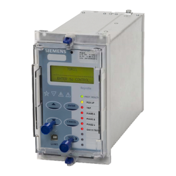
The device is identified by the rating label on the fascia. The user can also give the device its own identity by editing the ‘Relay Identifier’ displayed on the LCD or space is provided to place a slip in label giving the relays function. Siemens Protection Devices Limited... -
Page 10: Technical Data
Range 18 to 72 User Interface 5 Navigation Keys Weight Typical 3.1Kg Power Consumption: IP Rating Installed with IP 50 3.9W cover Allowable superimposed 12% of DC voltage ac component Allowable breaks/dips in 50ms supply (collapse to zero) Siemens Protection Devices Limited... -
Page 11: Serial Interface
(8-9Hz) 1gn and above ≤ 5 % Seismic response Conducted Radio Frequency Interference Y-plane – 1.5mm IEC 60255-22-6 displacement below crossover Type Level Variation freq (8-9Hz) 0.15 to 80 MHz 10 V ≤ 5 % 0.5gn above Siemens Protection Devices Limited... -
Page 12: Climatic Tests
35ms ±10ms Humidity Operate time following Tbasic +td , ±1% or ±10ms IEC 60068-2-78 delay. Overshoot Time < 40ms Operational test 56 days at 40 °C and 93 % Inhibited by Binary or Virtual Input relative humidity Siemens Protection Devices Limited... - Page 13 Disabled, 50,51…100% Inhibited by Binary or Virtual Input ± 5 % absolute or ± 30 ms Follower Delay 0 - 20s Reset ANSI decaying, 0 – 60s Inhibited by Binary or Virtual Input Inrush detector VT Supervision Siemens Protection Devices Limited...
- Page 14 64H Restricted Earth Fault Setting Range 0.05…0.95xIn Operate Level 100% Is, ±5% or ±1%xIn Time Delay 0.00… 14400s Basic Operate Time 0 to 2 xIs 45ms ±10ms 0 to 5 xIs 35ms ±10ms Inhibited by Binary or Virtual Input Siemens Protection Devices Limited...
-
Page 15: Case Dimensions
Case Dimensions Fig 14. E4 Case Dimensions Siemens Protection Devices Limited... - Page 16 7SR11 Connection Diagram Fig15. Diagram showing 7SR11 relay with 4 CT inputs, 6 binary inputs and 8 binary outputs. Siemens Protection Devices Limited...
- Page 17 7SR12 Connection Diagram Fig16. Diagram showing 7SR12 relay with 4 CT inputs, 3 VT inputs, 6 binary inputs and 8 binary outputs. Siemens Protection Devices Limited...
- Page 18 Ordering Information – 7SR11 Argus Non-Directional Overcurrent Product description Variants Order No. □ □ □ □ □ Nondirectional O/C Relay 7 S R 1 1 0 A 1 2 - ▲ ▲ ▲ ▲ ▲ ▲ ▲ ▲ ▲ | | | Overcurrent –...
- Page 19 Programmable logic Standard version – plus Autoreclose Additional Functionality No Additional Functionality 4CT is configured as 3PF + EF 4CT is configured as 3PF + SEF/REF Functions only available in 4CT relay Not available in SEF model Siemens Protection Devices Limited...
- Page 20 Siemens Protection Devices Limited P.O. Box 8 North Farm Road Hebburn Tyne and Wear NE31 1TZ United Kingdom Phone: +44 (0)191 401 7901 Fax: +44 (0)191 401 5575 Web: www.reyrolle-protection.com PTD 24h Customer Support Phone: +49 180 524 7000 Fax:...
Need help?
Do you have a question about the 7SR11 Argus and is the answer not in the manual?
Questions and answers