
Subscribe to Our Youtube Channel
Related Manuals for Siemens 7SR23 DAD


Summary of Contents for Siemens 7SR23 DAD
- Page 1 Reyrolle Protection Devices 7SR23 DAD High Impedance Protection Relay Answers for energy.
- Page 3 7SR23 DAD Contents Contents Technical Manual Chapters 1. Description of Operation 2. Settings, Configuration & Instruments 3. Performance Specification 4. Data Communications 5. Installation 6. Commissioning and Maintenance 7. Applications Guide ©2013 Siemens Protection Devices Limited...
- Page 4 7SR23 DAD Contents ©2013 Siemens Protection Devices Limited...
- Page 5 Limited. No part of this document shall be reproduced or modified or stored in another form, in any data retrieval system, without the permission of Siemens Protection Devices Limited, nor shall any model or article be reproduced from this document unless Siemens Protection Devices Limited consent.
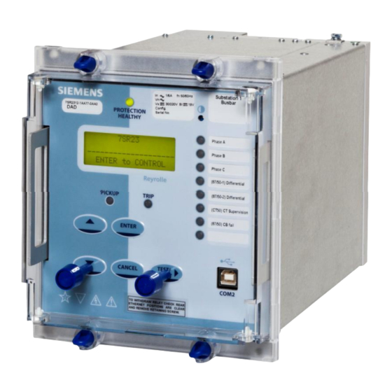
- Page 6 Chapter 1) 7SR23 DAD Description Of Operation ©2013 Siemens Protection Devices Limited Chapter 1 Page 2 of 36...
-
Page 7: Table Of Contents
Chapter 1) 7SR23 DAD Description Of Operation Contents Section 1: Introduction ........................6 Current Transformer Circuits......................6 External Resistors ........................6 Fibre Optic Communication ......................6 Front Cover ..........................6 Section 2: Hardware Description......................9 2.1 General..........................9 2.2 Case ............................9 2.3 Front Cover..........................9 2.4 Power Supply Unit (PSU) ....................10 2.5 Operator Interface/ Fascia....................10... - Page 8 6.9 Settings Groups .........................34 6.10 Password Feature ......................35 List of Figures Figure 1-1 Connection Diagram: 7SR23 DAD Relay.................8 Figure 2-1 7SR23 DAD with 3 + 8 LEDs in E6 Case ...............10 Figure 2-2 Binary Input Logic......................13 Figure 2-3 Binary Output Logic.......................15 Figure 3-1 Protection Functions......................16...
- Page 9 Chapter 1) 7SR23 DAD Description Of Operation Symbols and Nomenclature The following notational and formatting conventions are used within the remainder of this document: Setting Menu Location MAIN MENU>SUB-MENU Setting: Elem name -Setting Setting value: value Alternatives: [1st] [2nd] [3rd]...
-
Page 10: Section 1: Introduction
This manual is applicable to the following relays: 7SR23 DAD High Impedance Protection Relay The 7SR23 DAD relay integrates the protection elements required to provide high impedance protection relevant to busbars, connections, motors, reactors, transformers etc. The ‘Ordering Options’ Tables summarise the features available in each model. -
Page 11: Table 1-1 7Sr23 Dad Ordering Options
Chapter 1) 7SR23 DAD Description Of Operation Table 1-1 7SR23 DAD Ordering Options 7SR23 DAD 7 S R 2 3 0 - 0 C A 0 | | | High Impedance Protection | | | Protection Product Circulating Current Case I/O and Fascia... -
Page 12: Figure 1-1 Connection Diagram: 7Sr23 Dad Relay
Chapter 1) 7SR23 DAD Description Of Operation 7SR23 BO 7 BO 8 Data Comms Optional Analogue (Optional) BI 4 BI 5 Rear View BI 6 Arrangement of terminals and modules BI 7 NOTES BI 8 BI = Binary Input BO =... -
Page 13: Section 2: Hardware Description
Chapter 1) 7SR23 DAD Description Of Operation Section 2: Hardware Description General The structure of the relay is based upon the Multi-function hardware platform. The relays are supplied in either size E6 or size E8 cases (where 1 x E = width of approx. 26mm). The hardware design provides commonality between products and components across the Multi-function range of relays. -
Page 14: Power Supply Unit (Psu)
Figure 2-1 7SR23 DAD with 3 + 8 LEDs in E6 Case The fascia is an integral part of the relay. Handles are located at each side of the element to allow it to be withdrawn from the relay case. - Page 15 Chapter 1) 7SR23 DAD Description Of Operation 3) Blank label for user defined information. A template is available in the Reydisp programme to allow users to create and print customised LED labels. The warning and information labels on the relay fascia provide the following information:...
-
Page 16: Current Inputs
Chapter 1) 7SR23 DAD Description Of Operation Indication LEDs Relays have either 8 or 16 user programmable LED indicators. Each LED can be programmed to be illuminated as either green, yellow or red. Where an LED is programmed to be lit both red and green it will illuminate yellow. -
Page 17: Binary Inputs
Chapter 1) 7SR23 DAD Description Of Operation Binary inputs The binary inputs are isolated with opto-couplers and can be operated from a suitably rated dc supply. Relays are fitted with 9 or 19 binary inputs (BI). The user can assign any binary input to any of the available functions (INPUT CONFIG >... -
Page 18: Binary Outputs (Output Relays)
Chapter 1) 7SR23 DAD Description Of Operation Binary Outputs (Output Relays) Relays are fitted with 8 or 16 binary outputs. All outputs are fully user configurable and can be programmed to operate from any or all of the available functions. -
Page 19: Virtual Input/Outputs
Chapter 1) 7SR23 DAD Description Of Operation Logic signals, e.g. '51-1' Reset LEDs & Outputs (TEST/RESET key, Binary Input, Data Comms) BO 1 Output 1 Event Hand Reset & & BO 1 hand reset Min Operate Time & OUTPUT CONFIG>... -
Page 20: Section 3: Protection Functions
Chapter 1) 7SR23 DAD Description Of Operation Section 3: Protection Functions The relay is equipped with protection elements as shown in fig. 3.1. Figure 3-1 Protection Functions The above illustrates the SYSTEM CONFIG > Relay Config > USER settings. This setting gives the user access to all protection functions. -
Page 21: Overall High Impedance Differential Protection (87/50-N)
Chapter 1) 7SR23 DAD Description Of Operation Overall High Impedance Differential Protection (87/50-n) Two 87/50 high impedance elements are provided for each current input (87/50-1 and 87/50-2). The fundamental frequency current is measured by the phase CT inputs. 87/50-n Setting defines the current required to operate the differential element. 87/50-n outputs are available for any phase or for each individual phase. -
Page 22: Protection: Measured Earth Fault (50G)
Chapter 1) 7SR23 DAD Description Of Operation Protection: Measured Earth Fault (50G) The earth current is measured directly by the earth current input. These elements utilise either the true RMS current or the fundamental frequency RMS current (50 or 60Hz). -
Page 23: Protection: Restricted Earth Fault (87Ref)
Chapter 1) 7SR23 DAD Description Of Operation Protection: Restricted Earth Fault (87REF) Two 87REF elements are provided (87REF-1 and 87REF-2). 87REF-1 earth current is measured by the earth current input, 87REF-2 current is measured by the I current input. These elements utilise RMS current values of the fundamental frequency (50 or 60Hz). -
Page 24: Protection: Mode Selection
Chapter 1) 7SR23 DAD Description Of Operation Protection: Mode Selection 3.4.1 ‘3 Pole Diff’ + REF’ Operation The relay is configured for ‘3 Pole Diff +REF’ operation using the SYSTEM CONFIG > Relay Config > 3 Pole Diff + REF setting. Protection elements are automatically enabled as shown in Figure 3-5. -
Page 25: Pole Diff + Ef' Operation
Chapter 1) 7SR23 DAD Description Of Operation 3.4.2 ‘3 Pole Diff + EF’ Operation The relay can be used to provide both 3 phase differential and earth fault protections using the SYSTEM CONFIG > Relay Config > 3 Pole Diff + EF setting. -
Page 26: Ref1 + Ref2' Operation
Chapter 1) 7SR23 DAD Description Of Operation 3.4.3 ‘REF1 + REF2’ Operation The relay is configured for ‘REF1 + REF2’ operation using the SYSTEM CONFIG > Relay Config > REF1 + REF2 setting. When configured in this way the relay uses both 87REF elements. 87REF-1 earth current is measured by the earth current input, 87REF-2 current is measured by the I current input. -
Page 27: Section 4: Control & Logic Functions
Chapter 1) 7SR23 DAD Description Of Operation Section 4: Control & Logic Functions Zone Switching In/Out switching of the high impedance protections is provided to aid commissioning and testing. When the ‘Zone Switch Out’ feature is initiated the operation of the differential protection and CT supervision monitoring is inhibited. -
Page 28: Quick Logic
Chapter 1) 7SR23 DAD Description Of Operation Quick Logic The ‘Quick Logic’ feature allows the user to input up to 16 logic equations (E1 to E16) in text format. Equations can be entered using Reydisp or at the relay fascia. -
Page 29: Figure 4-2 Sequence Diagram Showing Pu/Do Timers In Quick Logic (Counter Reset Mode Off)
Chapter 1) 7SR23 DAD Description Of Operation Figure 4-2 Sequence Diagram showing PU/DO Timers in Quick Logic (Counter Reset Mode Off) When the count value = En Counter Target the output of the counter (En) = 1 and this value is held until the initiating conditions are removed when En is instantaneously reset. -
Page 30: Section 5: Supervision Functions
Chapter 1) 7SR23 DAD Description Of Operation Section 5: Supervision Functions CT Supervision (CT50) The CT supervision feature is phase segregated, outputs are provided for individual phases. Individual phases of the differential protections 87/50 can be blocked. Operation of the CT Supervision elements can be inhibited from: Inhibit CT50 A binary or virtual input. -
Page 31: Sustained Fault, Cb Fail & Cb Position Monitoring
Chapter 1) 7SR23 DAD Description Of Operation Sustained Fault, CB Fail & CB Position Monitoring The Sustained Fault Monitor (87/50SFM) feature can be used where either dedicated CB fail protection is not fitted and/or where the location of the protection CTs may introduce operational constraints. -
Page 32: Cb/Circuit Position Monitoring
Chapter 1) 7SR23 DAD Description Of Operation 5.2.1 CB/Circuit Position Monitoring The position of up to 12 CBs can be monitored utilising either the IEC61850 comms or wiring between binary inputs of the 7SR23 and CB auxiliary switches, in effect producing a replica of the busbar. -
Page 33: Trip Circuit Supervision (74Tcs)
Chapter 1) 7SR23 DAD Description Of Operation Trip Circuit Supervision (74TCS) The relay provides 12 trip circuit supervision elements. All elements are identical in operation and independent from each other allowing 12 trip circuits to be monitored. One or more binary inputs can be mapped to 74TCS-n. The inputs are connected into the trip circuit such that at least one input is energised when the trip circuit wiring is intact. -
Page 34: Section 6: Other Features
Chapter 1) 7SR23 DAD Description Of Operation Section 6: Other Features Data Communications Two communication ports, COM1 and COM2 are provided. RS485 connections are available on the terminal blocks at the rear of the relay (COM1). A USB port, COM 2, is provided at the front of the relay for local access using a PC. -
Page 35: Data Storage
Chapter 1) 7SR23 DAD Description Of Operation Data Storage 6.4.1 General The relay stores three types of data: relay event records, analogue/digital waveform records and fault records. Waveform records, fault records and event records are backed up in non-volatile memory and are permanently stored even in the event of loss of auxiliary supply voltage. -
Page 36: Metering
Chapter 1) 7SR23 DAD Description Of Operation To achieve accurate instrumentation values for the fault records when testing, ensure a drop off delay is applied to the test set so that the injected quantities remain on for a short duration, typically 20ms, after the relay has issued the trip output. -
Page 37: Operating Mode
Chapter 1) 7SR23 DAD Description Of Operation Operating Mode The relay has three operating modes, Local, Remote and Out of Service. The following table identifies the functions operation in each mode. The modes can be selected by the following methods: SYSTEM CONFIG>RELAY MODE setting, a Binary Input or Command... -
Page 38: Real Time Clock
Chapter 1) 7SR23 DAD Description Of Operation Real Time Clock The relay stores the time and date. The time and date are maintained while the relay is de-energised by a back up storage capacitor. The default date is set at 01/01/2000 deliberately to indicate the date has not yet been set. When editing the Time, only the hours and minutes can be edited. -
Page 39: Password Feature
The password validation screen also displays a numerical code. If the password is lost or forgotten, this code should be communicated to Siemens Protection Devices Ltd. and the password can be retrieved. ©2013 Siemens Protection Devices Limited Chapter 1 Page 35 of 36... - Page 40 Chapter 1) 7SR23 DAD Description Of Operation ©2013 Siemens Protection Devices Limited Chapter 1 Page 36 of 36...
- Page 41 Limited. No part of this document shall be reproduced or modified or stored in another form, in any data retrieval system, without the permission of Siemens Protection Devices Limited, nor shall any model or article be reproduced from this document unless Siemens Protection Devices Limited consent.
- Page 42 Chapter 2) 7SR23 DAD Settings, Configuration & Instruments Guide ©2013 Siemens Protection Devices Limited Chapter 2 Page 2 of 18...
- Page 43 Chapter 2) 7SR23 DAD Settings, Configuration & Instruments Guide Contents Section 1: Introduction ............................4 1.1 Relay Menus And Display ........................4 1.2 Operation Guide ..........................5 1.2.1 User Interface Operation ......................5 1.3 Settings Display..........................7 1.4 Instruments Mode..........................8 1.5 Fault Data Mode ..........................11 Section 2: Setting the Relay Using Reydisp Evolution ..................12...
-
Page 44: Section 1: Introduction
Chapter 2) 7SR23 DAD Settings, Configuration & Instruments Guide Section 1: Introduction Relay Menus And Display All relay fascias contain the same access keys although the fascias may differ in appearance from model to model. The basic menu structure is also the same in all products and consists of four main menus, these being, Settings Mode - allows the user to view and (if allowed by the settings mode password) change user settings in the relay from the fascia. -
Page 45: Operation Guide
Chapter 2) 7SR23 DAD Settings, Configuration & Instruments Guide Operation Guide 1.2.1 User Interface Operation The basic menu structure flow diagram is shown in Figure Figure 1-5. This diagram shows the main modes of display: Settings Mode, Instrument Mode, Fault Data Mode and Control Mode. - Page 46 Chapter 2) 7SR23 DAD Settings, Configuration & Instruments Guide When an instrument is displayed pressing ENTER will toggle the instruments favourite screen status. This push-button is used to return the relay display to its initial status or one level up in the menu structure.
-
Page 47: Settings Display
Chapter 2) 7SR23 DAD Settings, Configuration & Instruments Guide Settings Display The Settings Mode is reached by pressing the READ DOWN button from the relay identifier screen. Once the Settings Mode title screen has been located pressing the READ DOWN button takes the user into the Settings mode sub-menus. -
Page 48: Instruments Mode
Chapter 2) 7SR23 DAD Settings, Configuration & Instruments Guide Instruments Mode The Instrument Mode sub-menu displays key quantities and information to aid with commissioning. The following meters are available and are navigated around by using the and TEST/REST buttons. Instrument... - Page 49 Chapter 2) 7SR23 DAD Settings, Configuration & Instruments Guide prim secy Nom. prim secy Nom. prim secy Nom. prim secy Nom. 7SR23 DAD Figure 1-6 Schematic Diagram: 7SR23 Analogue Meters MAINTENANCE METERS This is the sub-group that includes all the meters that are...
- Page 50 Chapter 2) 7SR23 DAD Settings, Configuration & Instruments Guide VIRTUAL METERS This is the sub-group that shows the state of the virtual status inputs in the relay TEST/RESET allows access to this sub-group to view V 1-8 ---- ---- Displays the state of Virtual Outputs 1 to 16 (The number of virtual...
-
Page 51: Fault Data Mode
Chapter 2) 7SR23 DAD Settings, Configuration & Instruments Guide QUICK LOGIC METERS to view E 1-8 E 9-16 E1 Equation TMR 0-0 CNT 0-1 En Equation Fault Data Mode The Fault Data Mode sub menu lists the time and date of the previous ten protection operations. The stored data about each fault can be viewed by pressing the TEST/RESET button. -
Page 52: Section 2: Setting The Relay Using Reydisp Evolution
To configure the relay using a serial communication port the user will need the following:- PC with Reydisp installed. (This can be download from our website www.energy.siemens.com. Configuration and download of IEC 61850 data and programming of graphical user logic requires the use of the Reydisp Manager software which is supplied with online instructions and help and is not documented here. -
Page 53: Rear Rs485 Connection (Com1)
Chapter 2) 7SR23 DAD Settings, Configuration & Instruments Guide 2.1.2 Rear RS485 connection (COM1) Figure 2-2 RS485 connection to PC 2.1.3 Optional rear fibre optic connection (COM3 and COM4) 7SG244 USB or 9 pin male D connector RS232 straight Laptop computer through cable or 62.5/125µm fibre optic with ST... -
Page 54: Optional Rear Rs485 + Irig-B Connection (Com3)
Chapter 2) 7SR23 DAD Settings, Configuration & Instruments Guide 2.1.4 Optional rear RS485 + IRIG-B connection (COM3) COMMS MODULE IRIG-B COM3 RS485 Screened TERM twisted pair USB or 9 pin male D connector Laptop computer RS232 straight through cable Figure 2-4 Additional (Optional) rear RS485 + IRIG-B connection to a PC 2.1.5... -
Page 55: Optional Rear En100 Ethernet Module (Com3)
Chapter 2) 7SR23 DAD Settings, Configuration & Instruments Guide 2.1.6 Optional Rear EN100 Ethernet Module (COM3) The optional ethernet interface is primarily provided for support of IEC 61850 protocol. Support for IEC 870-5-103 is also provided over this interface to allow connection with Reydisp Evolution and Reydisp Manager software for interrogation, editing and download of relay settings and other data. -
Page 56: Configuring Relay Data Communication
Chapter 2) 7SR23 DAD Settings, Configuration & Instruments Guide 2.1.7 Configuring Relay Data Communication Using the keys on the relay fascia scroll down the settings menu’s into the ‘communications’ menu. All of the below settings may not be available in all relay types. Reydisp software is compatible with IEC60870-5-103 protocol. -
Page 57: Connecting The Relay For Use With Reydisp
Chapter 2) 7SR23 DAD Settings, Configuration & Instruments Guide Setting name Range Default Units Notes Setting is only visible when DNP3 Destination 0 … 65534 a port protocol is set to Address DNP3. Setting is only visible when DNP3 Application 5, 6 ... - Page 58 Chapter 2) 7SR23 DAD Settings, Configuration & Instruments Guide ©2013 Siemens Protection Devices Limited Chapter 2 Page 18 of 18...
- Page 59 Limited. No part of this document shall be reproduced or modified or stored in another form, in any data retrieval system, without the permission of Siemens Protection Devices Limited, nor shall any model or article be reproduced from this document unless Siemens Protection Devices Limited consent.
- Page 60 Chapter 3) 7SR23 DAD Performance Specification ©2013 Siemens Protection Devices Limited...
- Page 61 Chapter 3) 7SR23 DAD Performance Specification Contents Section 1: Type Testing .............................4 1.1 General .............................4 1.1.1 Certification - CE Conformity....................4 1.1.2 Reference ..........................4 1.2 Inputs and Outputs ..........................5 1.2.1 Auxiliary Power Supply......................5 1.2.2 AC Current...........................6 1.2.3 Binary (Digital) Outputs ......................7 1.2.4...
-
Page 62: Section 1: Type Testing
Chapter 3) 7SR23 DAD Performance Specification Section 1: Type Testing General 1.1.1 Certification - CE Conformity This product is CE compliant to relevant EU directives. 1.1.2 Reference 1.1.2.1 Accuracy Reference Conditions This product has been tested under the following conditions, unless specifically stated otherwise. -
Page 63: Inputs And Outputs
Chapter 3) 7SR23 DAD Performance Specification Inputs and Outputs 1.2.1 Auxiliary Power Supply Nominal Operating Range 30, 48, 110, 220 VDC 24 to 290 VDC 1.2.1.1 Burden Attribute Value Quiescent (typical) 7.5W 30V DC Quiescent (backlight) 9.0W Quiescent (typical) 7.3W... -
Page 64: Ac Current
Chapter 3) 7SR23 DAD Performance Specification 1.2.2 AC Current Nominal Measuring Range 1, 5 A Phase and earth 8 x In 50, 60Hz 47 to 63Hz Note. 1 A and 5 A nominal inputs are user selectable on each model. -
Page 65: Binary (Digital) Outputs
Chapter 3) 7SR23 DAD Performance Specification 1.2.3 Binary (Digital) Outputs Contact rating to IEC 60255-0-2 Attribute Value Carry continuously 5A AC or DC for 0.5 s 20A AC or DC Make and carry (L/R 40 ms and V 300 V) for 0.2 s... - Page 66 Chapter 3) 7SR23 DAD Performance Specification ESI-1 ESI-2 30V DC Nominal 30V DC Nominal (24 – 37.5V Operative) (24 – 37.5V Operative) > 10mA > 20mA BI (19V) BI (19V) 48V DC Nominal 48V DC Nominal (37.5 – 60V Operative) (37.5 –...
-
Page 67: Instrumentation And Data Comms
Chapter 3) 7SR23 DAD Performance Specification Instrumentation and Data Comms 1.3.1 Instrumentation Instrument Value Reference Typical accuracy Current 0.1 xIn 1 % In 1.3.2 Data Communication 1.3.2.1 USB Data Communication Interface Attribute Value Physical layer Electrical Connectors USB-Type B 1.3.2.2... -
Page 68: Real Time Clock
Chapter 3) 7SR23 DAD Performance Specification 1.3.2.7 Electrical Ethernet Data Communication Interface (IEC 61850 Option) Attribute Value Physical Layer Electrical Connectors RJ45 100BaseF in acc. With IEEE802.3 Transmission Speed 100MBit/s Test Voltage (with regard to socket) 500 VAC 50 Hz Bridgeable distance 1.3.3... -
Page 69: Environmental Performance
Chapter 3) 7SR23 DAD Performance Specification Environmental Performance 1.4.1 Atmospheric Environment 1.4.1.1 Temperature IEC 60068-2-1/2 Type Level Operating range -10 C to +55 C Storage range -25 C to +70 C 1.4.1.2 Humidity IEC 60068-2-78 Type Level Operational test 56 days at 40 C and 93 % relative humidity 1.4.2... - Page 70 Chapter 3) 7SR23 DAD Performance Specification 1.4.2.5 High Frequency Disturbance (Immunity) / 1MHz Burst High Frequency Disturbance IEC 60255-22-1 Type Level Variation Case, Aux Power & I/O Common (longitudinal) mode 2.5 kV 10 % Case, Aux Power & I/O Series (transverse) mode 1.0 kV...
-
Page 71: Mechanical Environment
Chapter 3) 7SR23 DAD Performance Specification 1.4.2.11 Magnetic Field with Power Frequency (Immunity) IEC 6100-4-8 Level 5, 100A/m, (0.126mT) continuous 50Hz 1000A/m, (1.26mT) for 3s 1.4.3 Mechanical Environment 1.4.3.1 Vibration (Sinusoidal) IEC 60255-21-1 Class I, Type Level Variation Vibration response 0.5 gn... -
Page 72: Mechanical
Chapter 3) 7SR23 DAD Performance Specification Mechanical 1.5.1.1 Dimensions Parameter Value 7SR DAD, E6 case 155.5 mm Width 7SR DAD, E8 case 207.5 mm Height 177 mm Depth behind panel 216.5 mm 241.5mm (including clearance for terminal wiring) Depth behind panel (including clearances) 286.5mm (including clearance for F/O cabling) -
Page 73: Section 2: Protection Functions
Chapter 3) 7SR23 DAD Performance Specification Section 2: Protection Functions 50G Instantaneous Measured Earth Fault 2.1.1 Reference Parameter Value Setting 0.01…2.0 xIn Delay setting 0, 0.005…1.0, 1.01…5,5.1…60s 2.1.2 Operate and Reset Level Attribute Value Operate level 100 % Is, 5 % or... -
Page 74: 87/50 High Impedance Differential Protection
Chapter 3) 7SR23 DAD Performance Specification 87/50 High Impedance Differential Protection 2.2.1 Reference Parameter Value Setting 0.010,0.011…0.100,0.105…2xIn Delay setting 0, 0.005…1.0, 1.01…5,5.1…60s 2.2.2 Operate and Reset Level Attribute Value Operate level 100 % Is, 5 % or 1% xIn Reset level... -
Page 75: 87Ref Restricted Earth Fault Protection
Chapter 3) 7SR23 DAD Performance Specification 87REF Restricted Earth Fault Protection 2.3.1 Reference Parameter Value Setting 0.010,0.011…0.100,0.105…2xIn Delay setting 0, 0.005…1.0, 1.01…5,5.1…60s 2.3.2 Operate and Reset Level Attribute Value Operate level 100 % Is, 5 % or 1% xIn Reset level... -
Page 76: Section 3: Supervision Functions
Chapter 3) 7SR23 DAD Performance Specification Section 3: Supervision Functions CT50 CT Supervision Monitoring 3.1.1 Reference Parameter Value Setting 0.005,0.006…0.100,0.105…2xIn Delay setting 0, 0.005…1.0, 1.01…5,5.1…60s 3.1.2 Operate and Reset Level Attribute Value Operate level 100 % Is, 5 % or... -
Page 77: 74Tcs Trip Circuit Supervision
Chapter 3) 7SR23 DAD Performance Specification 74TCS Trip Circuit Supervision 3.2.1 Reference Parameter Value Delay setting 0, 0.02…60 s 3.2.2 Operate and Reset Time Attribute Value Element basic operate time 30ms 10ms basic Operate time following delay 1 % or... - Page 78 Chapter 3) 7SR23 DAD Performance Specification ©2013 Siemens Protection Devices Limited Chapter 3 Page 20 of 20...
- Page 79 Limited. No part of this document shall be reproduced or modified or stored in another form, in any data retrieval system, without the permission of Siemens Protection Devices Limited, nor shall any model or article be reproduced from this document unless Siemens Protection Devices Limited consent.
- Page 80 Chapter 4) 7SR23 DAD Data Communications ©2013 Siemens Protection Devices Limited Chapter 4 Page 2 of 54...
- Page 81 Chapter 4) 7SR23 DAD Data Communications Contents Document Release History..........................1 Section 1: Introduction ............................4 Section 2: Physical Connection ..........................5 2.1 Communication ports .........................6 2.1.1 USB Interface (COM2) ......................6 2.1.2 RS485 Interface (COM1)......................7 2.1.3 Optional Rear Fibre Optic Interfaces (COM3 and COM4)............8 2.1.4...
-
Page 82: Section 1: Introduction
When IEC60870-5-103 protocol is selected the relay can communicate with PCs running Reydisp software which provides operational information, post-fault analysis, settings interrogation and editing facilities etc. Reydisp software can be downloaded from our website www.energy.siemens.com. ©2013 Siemens Protection Devices Limited... -
Page 83: Section 2: Physical Connection
SPDL can provide a range of interface devices, please refer to product portfolio catalogue. Full details of the interface devices can be found by referring to the website www.energy.siemens.com. ©2013 Siemens Protection Devices Limited Chapter 4 Page 5 of 54... -
Page 84: Communication Ports
Chapter 4) 7SR23 DAD Data Communications Communication ports To allow communication to the relay the Station Address setting must be within the range of the selected protocol i.e. 0 – 254 for IEC60870-5-103, 0 – 247 for MODBUS-RTU or 0 – 65520 for DNP3. -
Page 85: Rs485 Interface (Com1)
Chapter 4) 7SR23 DAD Data Communications 2.1.2 RS485 Interface (COM1) The RS485 communication port is located on the rear of the relay and can be connected using a suitable RS485 120 Ohm screened twisted pair cable. The RS485 electrical connection can be used in a single or multi-drop configuration. The RS485 master must support and use the Auto Device Enable (ADE) feature. -
Page 86: Optional Rear Fibre Optic Interfaces (Com3 And Com4)
Chapter 4) 7SR23 DAD Data Communications 2.1.3 Optional Rear Fibre Optic Interfaces (COM3 and COM4) When connecting via the optional fibre optic interface the selection of fibre-optic cable is important. Fibres must be terminated with ST (BFOC/2.5) connectors. The recommended type is 62.5/125µm glass fibre. Communication distances over 1 km are achievable using this type of fibre. - Page 87 Chapter 4) 7SR23 DAD Data Communications The following table can be used to record budget calculations: Launch power Fibre Type Loss (dB/km) dB/km Length Total fibre loss (CxD) No. of Splices Loss at each splice Total loss at splices (FxG) No.
- Page 88 Chapter 4) 7SR23 DAD Data Communications Setting name Range Default Setting Notes An address within the range of 1 – 254 for IEC60870-5-103 the relevant protocol must be 0 – 247 for Modbus RTU As Required Station Address given to identify the relay. Each...
- Page 89 Chapter 4) 7SR23 DAD Data Communications Figure 2-3 Communication to Multiple Devices using Fibre-optic Ring Network Figure 2-4 Communication to Multiple Devices from Control System and Laptop using Fibre-optic Star Network ©2013 Siemens Protection Devices Limited Chapter 4 Page 11 of 54...
-
Page 90: Optional Rear Rs485 (Com3)
Chapter 4) 7SR23 DAD Data Communications 2.1.4 Optional Rear RS485 (COM3) 7SR24 COMMS MODULE IRIG-B COM3 RS485 Screened TERM twisted pair USB or 9 pin male D connector Laptop computer RS232 straight through cable Figure 2-5 Additional (Optional) Rear RS485 + IRIG-B Connection to a PC 2.1.5... -
Page 91: Optional Rear En100 Ethernet Module (Com3)
Chapter 4) 7SR23 DAD Data Communications 2.1.6 Optional Rear EN100 Ethernet Module (COM3) The optional ethernet interface is primarily provided for support of IEC 61850 protocol. Support for IEC 60870-5- 103 is also provided over this interface to allow connection with Reydisp Evolution and Reydisp Manager software for interrogation, editing and download of relay settings and other data. -
Page 92: Section 3: Iec 60870-5-103 Definitions
Chapter 4) 7SR23 DAD Data Communications Section 3: IEC 60870-5-103 Definitions Introduction This section describes the IEC 60870-5-103 protocol implementation in the relays. This protocol is used for the communication with REYDISP software and can also be used for communication with a suitable control system. - Page 93 Chapter 4) 7SR23 DAD Data Communications Table 1: IEC60870-5-103 Event List Description Remote Mode Service Mode Local Mode Local & Remote Control Received Command Received Cold Start Warm Start Re-Start Trigger Storage Clear Waveform Records Clear Fault Records Clear Event Records...
- Page 94 Chapter 4) 7SR23 DAD Data Communications Description Virtual Input 6 Virtual Input 7 Virtual Input 8 Virtual Input 9 Virtual Input 10 Virtual Input 11 Virtual Input 12 Virtual Input 13 Virtual Input 14 Virtual Input 15 Virtual Input 16...
- Page 95 Chapter 4) 7SR23 DAD Data Communications Description Start/Pick-up L2 Start/Pick-up L3 Start/Pick-up N General Trip Trip L1 Trip L2 Trip L3 General Start/Pick-up 87/50-1 87/50-2 87/50 CT Supervision Setting G5 selected Setting G6 selected Setting G7 selected Setting G8 selected...
- Page 96 Chapter 4) 7SR23 DAD Data Communications Description CB12 Cct Travel Alarm Ext 87 CBF Input Ext 87 CBF1 Ext 87 CBF2 Ext 87 CBF3 Ext 87 CBF4 Ext 87 CBF5 Ext 87 CBF6 Ext 87 CBF7 Ext 87 CBF8 Ext 87 CBF9...
- Page 97 Chapter 4) 7SR23 DAD Data Communications Description CB2 Total Open Count CB2 Delta Open Count Reset CB2 Total Open Count Reset CB2 Delta Open Count CB2 Total Open Count ASDU4 CB2 Delta Open Count ASDU4 CB3 Total Open Count CB3 Delta Open Count...
- Page 98 Chapter 4) 7SR23 DAD Data Communications Description CB12 Total Open Count ASDU4 CB12 Delta Open Count ASDU4 Ia Fault Current Ib Fault Current Ic Fault Current Ig Fault Current Ig2 Fault Current CB 1 CB 2 CB 3 CB 4...
- Page 99 Chapter 4) 7SR23 DAD Data Communications Table 4: IEC60870-5-103 Command Numbers Description Remote Mode Service Mode Local Mode Local & Remote Binary Output 1 Binary Output 2 Binary Output 3 Binary Output 4 Binary Output 5 Binary Output 6 Binary Output 7...
- Page 100 Chapter 4) 7SR23 DAD Data Communications Description Reset CB12 Delta Open Count User SP Command 1 User SP Command 2 User SP Command 3 User SP Command 4 User SP Command 5 User SP Command 6 User SP Command 7...
-
Page 101: Section 4: Modbus Definitions
Chapter 4) 7SR23 DAD Data Communications Section 4: Modbus Definitions Introduction This section describes the MODBUS-RTU protocol implementation in the relays. This protocol is used for communication with a suitable control system. This protocol can be set to use the Fibre Optic and RS485 ports. The relay can communicate simultaneously on all ports regardless of protocol used. - Page 102 Chapter 4) 7SR23 DAD Data Communications Write Address Description Only 00138 Reset CB3 Delta Cnt 00139 Reset CB4 Open Cnt 00140 Reset CB4 Delta Cnt 00141 Reset CB5 Open Cnt 00142 Reset CB5 Delta Cnt 00143 Reset CB6 Open Cnt...
- Page 103 Chapter 4) 7SR23 DAD Data Communications Table 6: Modbus-RTU Inputs (Read Only) Address Description 10001 Binary Input 1 10002 Binary Input 2 10003 Binary Input 3 10004 Binary Input 4 10005 Binary Input 5 10006 Binary Input 6 10007 Binary Input 7...
- Page 104 Chapter 4) 7SR23 DAD Data Communications Address Description 10510 Virtual Input 10 10511 Virtual Input 11 10512 Virtual Input 12 10513 Virtual Input 13 10514 Virtual Input 14 10515 Virtual Input 15 10516 Virtual Input 16 10601 LED 1 10602...
- Page 105 Chapter 4) 7SR23 DAD Data Communications Address Description 12606 87/50G-1 12607 87/50AB-1 12608 87/50BC-1 12609 87/50CA-1 12610 87/50AG-1 12611 87/50BG-1 12612 87/50CG-1 12613 87/50A-2 12614 87/50B-2 12615 87/50C-2 12616 87/50G-2 12617 87/50AB-2 12618 87/50BC-2 12619 87/50CA-2 12620 87/50AG-2 12621 87/50BG-2...
- Page 106 Chapter 4) 7SR23 DAD Data Communications Address Description 12733 CB4 Cct Close Alarm 12734 CB5 Cct Close Alarm 12735 CB6 Cct Close Alarm 12736 CB7 Cct Close Alarm 12737 CB8 Cct Close Alarm 12738 CB9 Cct Close Alarm 12739 CB10 Cct Close Alarm...
- Page 107 Chapter 4) 7SR23 DAD Data Communications Table 7: MODBUS-RTU Registers Address Name Format Description 30001 No.of Events In Store 1 Register 30002 Event Record 8 Registers 30010 Number of Fault Records 1 Register 30012 Number of Event Records 1 Register...
- Page 108 Chapter 4) 7SR23 DAD Data Communications Table 8: MODBUS-RTU Holding Registers (Read Write Values) Address Name Format Description 40001 Time Meter 40380 Start Count FP_32BITS_3DP 40382 Start Count Target FP_32BITS_3DP 40200 Ig-1 Primary (A) FP_32BITS_3DP 40202 Ig-1 Secondary (A) FP_32BITS_3DP...
-
Page 109: Section 5: Dnp3.0 Definitions
(Also see the DNP 3.0 Implementation Table in Section 5.2, beginning on page 34.) Vendor Name: Siemens Protection Devices Ltd. Device Name: 7SR23 DAD, using the Triangle MicroWorks, Inc. DNP3 Slave Source Code Library, Version 3. Highest DNP Level Supported: Device Function:... - Page 110 Chapter 4) 7SR23 DAD Data Communications DNP V3.0 DEVICE PROFILE DOCUMENT (Also see the DNP 3.0 Implementation Table in Section 5.2, beginning on page 34.) Timeouts while waiting for: Data Link Confirm: None Fixed - 2sec Variable Configurable. Complete Appl. Fragment:...
- Page 111 Chapter 4) 7SR23 DAD Data Communications DNP V3.0 DEVICE PROFILE DOCUMENT (Also see the DNP 3.0 Implementation Table in Section 5.2, beginning on page 34.) Sends Unsolicited Responses: Sends Static Data in Unsolicited Responses: Never Never Configurable When Device Restarts...
-
Page 112: Implementation Table
Chapter 4) 7SR23 DAD Data Communications Implementation Table The following table identifies which object variations, function codes, and qualifiers the Triangle MicroWorks, Inc. DNP 3.0 Slave Source Code Library supports in both request messages and in response messages. For static (non-change-event) objects, requests sent with qualifiers 00, 01, 06, 07, or 08, will be responded with qualifiers 00 or 01. - Page 113 Chapter 4) 7SR23 DAD Data Communications REQUEST RESPONSE OBJECT (Library will parse) (Library will respond with) Object Variation Function Codes Qualifier Codes Function Codes Qualifier Description Number Number (dec) (hex) (dec) Codes (hex) Binary Input – Any 00, 01 (read)
- Page 114 Chapter 4) 7SR23 DAD Data Communications REQUEST RESPONSE OBJECT (Library will parse) (Library will respond with) Object Variation Function Codes Qualifier Codes Function Codes Qualifier Description Number Number (dec) (hex) (dec) Codes (hex) 32-Bit Frozen Delta Counter (with Flag) 16-Bit Frozen Delta...
- Page 115 Chapter 4) 7SR23 DAD Data Communications REQUEST RESPONSE OBJECT (Library will parse) (Library will respond with) Object Variation Function Codes Qualifier Codes Function Codes Qualifier Description Number Number (dec) (hex) (dec) Codes (hex) 16-Bit Counter 17, 28 (read) (no range, or all)
- Page 116 Chapter 4) 7SR23 DAD Data Communications REQUEST RESPONSE OBJECT (Library will parse) (Library will respond with) Object Variation Function Codes Qualifier Codes Function Codes Qualifier Description Number Number (dec) (hex) (dec) Codes (hex) 32-Bit Analog (read) 06(no range, or all)
-
Page 117: Point List
Chapter 4) 7SR23 DAD Data Communications Point List The tables below identify all the default data points provided by the implementation of the Triangle MicroWorks, Inc. DNP 3.0 Slave Source Code Library. Table 11: DNP3.0 Binary Input Points Binary Input Points... - Page 118 Chapter 4) 7SR23 DAD Data Communications Default Variation Default Variation Point Default Name/Description Event Object 1 Event Object 2 Index class Trip Circuit Fail 6 Trip Circuit Fail 7 Trip Circuit Fail 8 Trip Circuit Fail 9 Trip Circuit Fail 10...
- Page 119 Chapter 4) 7SR23 DAD Data Communications Default Variation Default Variation Point Default Name/Description Event Object 1 Event Object 2 Index class Binary Output 15 Binary Output 16 Setting G1 Selected Setting G2 Selected Setting G3 Selected Setting G4 Selected Setting G5 Selected...
- Page 120 Chapter 4) 7SR23 DAD Data Communications Default Variation Default Variation Point Default Name/Description Event Object 1 Event Object 2 Index class CB1 Open Cnt CB1 Delta Cnt CB2 Open Cnt CB2 Delta Cnt CB3 Open Cnt CB3 Delta Cnt CB4 Open Cnt...
- Page 121 Chapter 4) 7SR23 DAD Data Communications Default Variation Default Variation Point Default Name/Description Event Object 1 Event Object 2 Index class CB4 Cct Travel Alarm CB5 Cct Travel Alarm CB6 Cct Travel Alarm CB7 Cct Travel Alarm CB8 Cct Travel Alarm...
- Page 122 Chapter 4) 7SR23 DAD Data Communications Default Variation Default Variation Point Default Name/Description Event Object 1 Event Object 2 Index class LED 14 LED 15 LED 16 Cold Start Warm Start Re-Start Power On Table 12: DNP3.0 Double Point Binary Input Points...
- Page 123 Chapter 4) 7SR23 DAD Data Communications Table 13: DNP3.0 Binary Output Status Points and Control Relay Output Blocks Binary Output Status Points Static (Steady-State) Object Number: 10 Change Event Object Number: 11 Static Variation reported when variation 0 requested: 2 (Binary Output status with Flags)
- Page 124 Chapter 4) 7SR23 DAD Data Communications Default Default Default Default Supported Point Name/ Class Static Event CROB CROB Index Description Object 10 Object 11 fields Fields Variation Variation Latch On Pulse On Service Mode Pulse On Latch On Pulse On...
- Page 125 Chapter 4) 7SR23 DAD Data Communications Default Default Default Default Supported Point Name/ Class Static Event CROB CROB Index Description Object 10 Object 11 fields Fields Variation Variation Latch On Pulse On User SP Command 1 Pulse On Latch On...
- Page 126 Chapter 4) 7SR23 DAD Data Communications Table 14 lists Analog Inputs (Object 30). It is important to note that 16-bit and 32-bit variations of Analog Inputs, Analog Output Control Blocks, and Analog Output Statuses are transmitted through DNP as signed numbers.
- Page 127 Chapter 4) 7SR23 DAD Data Communications Table 14: DNP3.0 Analog Inputs Analog Inputs Static (Steady-State) Object Number: 30 Change Event Object Number: 32 Default Static Variation reported when variation 0 requested: 3 (32-Bit Analog Input with Flag), 4 (16-Bit Analog input w/o Flag)
- Page 128 Chapter 4) 7SR23 DAD Data Communications Table 15: DNP3.0 Counters Counters Static (Steady-State) Object Number: 20 Change Event Object Number: 22 Default Static Variation reported when variation 0 requested: 5 (32-Bit Counter without Flag) Default Change Event Variation reported when variation 0 requested: 1 (32-Bit Change Event with Flag)
- Page 129 Chapter 4) 7SR23 DAD Data Communications Default Point Data Default Change Event Name/Description Multiplier Index Type Deadband Assigned Class (1, 2, 3 or none) CB12 Open Cnt CB12 Delta Cnt ©2013 Siemens Protection Devices Limited Chapter 4 Page 51 of 54...
-
Page 130: Section 6: Iec61850 Protocol Support
Chapter 4) 7SR23 DAD Data Communications Section 6: IEC61850 Protocol Support The relay can optionally be provided with IEC61850 comms. For further details refer to the following publications: Model Implementation Conformance Statement (MICS) Protocol Implementation Conformance Statement (PICS) Protocol Implementation Extra Information for Testing (PIXIT) ©2013 Siemens Protection Devices Limited... -
Page 131: Section 7: Modems
Chapter 4) 7SR23 DAD Data Communications Section 7: Modems The communications interface has been designed to allow data transfer via modems. However, IEC 60870-5-103 defines the data transfer protocol as an 11 bit format of 1 start, 1 stop, 8 data and even parity, which is a mode most commercial modems do not support. -
Page 132: Section 8: Glossary
Chapter 4) 7SR23 DAD Data Communications Section 8: Glossary Baud Rate Data transmission speed. The smallest measure of computer data. Bits Per Second (bps) Measurement of data transmission speed. Data Bits A number of bits containing the data. Sent after the start bit. - Page 133 Limited. No part of this document shall be reproduced or modified or stored in another form, in any data retrieval system, without the permission of Siemens Protection Devices Limited, nor shall any model or article be reproduced from this document unless Siemens Protection Devices Limited consent.
- Page 134 Chapter 5) 7SR23 DAD Installation Guide ©2013 Siemens Protection Devices Limited Chapter 5 Page 2 of 24...
- Page 135 Chapter 5) 7SR23 DAD Installation Guide Contents Document Release History .......................1 Contents............................3 List of Figures ...........................4 Section 1: Installation ........................5 1.1 Packaging ..........................5 1.2 Unpacking, Storage and Handling ..................5 1.3 Recommended Mounting Position ..................5 1.4 Wiring ..........................5 1.5 Earthing ..........................5 1.6 Ancillary Equipment......................6...
- Page 136 Chapter 5) 7SR23 DAD Installation Guide List of Figures Figure 3.1-1 Overall Dimensions and panel Drilling for Size E6 Epsilon case........8 Figure 3.1-2 Overall Dimensions and panel Drilling for Size E8 Epsilon case........9 Figure 4.1-1 E6 Standard Comms (USB Front Port, Rear RS485) (See Note 2).........11 Figure 4.1-2 E6 Standard + Additional Ports (IRIG-B, 2 x F.O.
-
Page 137: Packaging
If damage has been sustained a claim should be immediately be made against the carrier, also inform Siemens Protection Devices Limited and to the nearest Siemens agent, using the Defect Report Form in the Maintenance section of this manual. -
Page 138: Ancillary Equipment
Chapter 5) 7SR23 DAD Installation Guide 1.6 Ancillary Equipment The relay can be interrogated locally or remotely. For local interrogation a portable PC with suitable version of MS Windows and Reydisp Evolution or Reydisp Manager software using the USB port situated on front of the relay. -
Page 139: Section 2: Equipment Operating Conditions
Chapter 5) 7SR23 DAD Installation Guide Section 2: Equipment Operating Conditions General Safety Precautions Current Transformer Circuits The secondary circuit of a live CT must not be open circuited. Non-observance of this precaution can result in injury to personnel or damage to equipment. -
Page 140: Section 3: Dimensions And Panel Fixings
Chapter 5) 7SR23 DAD Installation Guide Section 3: Dimensions and Panel Fixings 3.1 Relay Dimensions and Weight Relays are supplied in size E6 and E8 cases. Panel cut-out requirements and case dimensions are shown in Figure 3.1-1 and Figure 3.1-2 below. - Page 141 Chapter 5) 7SR23 DAD Installation Guide 254.5 Optional ethernet 207.5 216.5 comms module Case Earth connection Typical when FRONT VIEW fitted SIDE VIEW 25mm MIN CLEARANCE FOR TERMINAL WIRING 70mm MIN CLEARANCE FOR F/O COMMS CABLE 75mm MIN CLEARANCE BELOW EN100 MODULE FOR ETHERNET COMMS CONNECTIONS 201.5...
-
Page 142: Fixings
Chapter 5) 7SR23 DAD Installation Guide Fixings 3.2.1 Crimps Ring tongued crimps with 90 bend are recommended. 3.2.2 Panel Fixings Typical mounting screw kit (per Relay) Consists of 4 off M4x10mm Screws 4 off M4 Nuts 4 off M4 Lock Washer... -
Page 143: Section 4: Rear Terminal Drawings
Chapter 5) 7SR23 DAD Installation Guide Section 4: Rear Terminal Drawings E6 Case Figure 4.1-1 E6 Standard Comms (USB Front Port, Rear RS485) (See Note 2) Figure 4.1-2 E6 Standard + Additional Ports (IRIG-B, 2 x F.O. (ST Connectors) ©2013 Siemens Protection Devices Limited... - Page 144 Chapter 5) 7SR23 DAD Installation Guide Figure 4.1-3 E6 Standard + Additional Ports (IRIG-B, RS485) Figure 4.1-4 E6 Standard + Additional Ports (IRIG-B, RS232) Notes 1) Recommended terminations are pre-insulated & must be crimped using approved tooling. 2) RS485 (block ”B” terminals 14, 16, 18, 20 and optional COMMS MODULE) connections are by screened, twisted pair cable.
-
Page 145: E8 Case
Chapter 5) 7SR23 DAD Installation Guide E8 Case Figure 4.2-1 E8 Standard Comms (USB Front Port, Rear RS485) (See Note 2) Figure 4.2-2 E8 Standard + Additional Ports (IRIG-B, 2 x F.O. (ST Connectors) ©2013 Siemens Protection Devices Limited Chapter 5 Page 13 of 24... - Page 146 Chapter 5) 7SR23 DAD Installation Guide Figure 4.2-3 E8 Standard + Additional Ports (IRIG-B, RS485) Figure 4.2-4 E8 Standard + Additional Ports (IRIG-B, RS232) Notes 1) Recommended terminations are pre-insulated & must be crimped using approved tooling. 2) RS485 (block ”B” terminals 14, 16, 18, 20 and optional COMMS MODULE) connections are by screened, twisted pair cable.
-
Page 147: Section 5: Connection/Wiring/Diagrams
Chapter 5) 7SR23 DAD Installation Guide Section 5: Connection/Wiring/Diagrams Wiring Diagram: 7SR230 Relay Figure 5.1-1 7SR23 Wiring Diagram ©2013 Siemens Protection Devices Limited Chapter 5 Page 15 of 24... -
Page 148: Section 6: Data Comms Connections
Chapter 5) 7SR23 DAD Installation Guide Section 6: Data Comms Connections RS485 Connection The RS485 communication port terminals are located on the rear of the relay and can be connected using a suitable RS485 120 screened twisted pair cable. The RS485 electrical connection can be used in a single or multi-drop configuration. When used with Reydisp the RS485 master must support and use the Auto Device Enable (ADE) feature. - Page 149 Chapter 5) 7SR23 DAD Installation Guide Figure 6.3-1 Data Comms to Multiple Devices Using Sigma 1 and F.O. Star Network Figure 6.3-2 Data Comms to Multiple Devices Using Sigma 3 and F.O. Ring Network ©2013 Siemens Protection Devices Limited Chapter 5 Page 17 of 24...
-
Page 150: Optional Additional Rs485 Connections
Chapter 5) 7SR23 DAD Installation Guide Optional Additional RS485 Connections The additional (optional) RS485 communication port is located at the rear of the relay and can be connected using a suitable RS485 120 ohm screened twisted pair cable. The RS485 electrical connection can be used in a single or multi-drop configuration. When used with Reydisp the RS485 master must support and use the Auto Device Enable (ADE) feature. -
Page 151: Additional (Optional) Ethernet Connection For Iec 61850
Chapter 5) 7SR23 DAD Installation Guide Additional (Optional) Ethernet Connection for IEC 61850 Rear Ethernet Comms port Ch 1 and Ch 2 comprises Fibre–Optic Duplex LC connectors or electrical RJ45 connectors. When installing fibre, ensure that the fibres’ bend radii comply with the recommended minimum for the fibre used- typically 50mm is acceptable, 62.5 / 125 m glass fibre is recommended for all distances. -
Page 152: Section 7: Connection Diagrams
Chapter 5) 7SR23 DAD Installation Guide Connection Diagrams Section 7: Typical AC Connections: 3 Pole Differential Figure 7.1-1 Connections 3 Pole Differential ©2013 Siemens Protection Devices Limited Chapter 5 Page 20 of 24... -
Page 153: Typical Ac Connections: 3 Pole Differential + Earth Fault
Chapter 5) 7SR23 DAD Installation Guide Typical AC Connections: 3 Pole Differential + Earth Fault Figure 7.2-1 Connections 3 Pole Differential + Earth Fault ©2013 Siemens Protection Devices Limited Chapter 5 Page 21 of 24... -
Page 154: Typical Ac Connections: 3 Pole Differential + Ref
Chapter 5) 7SR23 DAD Installation Guide Typical AC Connections: 3 Pole Differential + REF Figure 7.3-1 Connections 3 Pole Differential + Restricted Earth Fault ©2013 Siemens Protection Devices Limited Chapter 5 Page 22 of 24... -
Page 155: Typical Ac Connections: Ref1 + Ref2
Chapter 5) 7SR23 DAD Installation Guide Typical AC Connections: REF1 + REF2 Figure 7.4-1 Connections Restricted Earth Fault 1 and 2 ©2013 Siemens Protection Devices Limited Chapter 5 Page 23 of 24... - Page 156 Chapter 5) 7SR23 DAD Installation Guide ©2013 Siemens Protection Devices Limited Chapter 5 Page 24 of 24...
- Page 157 Limited. No part of this document shall be reproduced or modified or stored in another form, in any data retrieval system, without the permission of Siemens Protection Devices Limited, nor shall any model or article be reproduced from this document unless Siemens Protection Devices Limited consent.
- Page 158 Chapter 6) 7SR23 DAD Commissioning & Maintenance Guide ©2013 Siemens Protection Devices Limited Chapter 6 Page 2 of 26...
- Page 159 Chapter 6) 7SR23 DAD Commissioning & Maintenance Guide Contents Document Release History .......................1 Contents............................3 Section 1: Common Functions......................5 1.1 Overview..........................5 1.2 Before Testing........................5 1.2.1 Safety ........................5 1.2.2 Sequence of Tests....................5 1.2.3 Test Equipment......................6 1.2.4 Precautions......................6 1.2.5 Applying Settings .....................7 1.3 Tests............................8 1.3.1...
- Page 160 Chapter 6) 7SR23 DAD Commissioning & Maintenance Guide List of Figures Figure 2-1 Measured Earth Fault......................13 Figure 2-2 3 Phase Differential Protection ..................14 Figure 2-3 Restricted Earth Fault......................16 Figure 3-1 CT Supervision ........................19 ©2013 Siemens Protection Devices Limited Chapter 6 Page 4 of 26...
-
Page 161: Section 1: Common Functions
Chapter 6) 7SR23 DAD Commissioning & Maintenance Guide Section 1: Common Functions Overview Commissioning tests are carried out to prove: Equipment has not been damaged in transit. Equipment has been correctly connected and installed. Prove characteristics of the protection and settings which are based on calculations. -
Page 162: Test Equipment
Chapter 6) 7SR23 DAD Commissioning & Maintenance Guide 1.2.3 Test Equipment Required test equipment is: Secondary injection equipment with integral time interval meter Primary injection equipment A d.c. supply with nominal voltage within the working range of the relay's d.c. auxiliary supply rating A d.c. -
Page 163: Applying Settings
Chapter 6) 7SR23 DAD Commissioning & Maintenance Guide 1.2.5 Applying Settings The relay settings for the particular application should be applied before any secondary testing occurs. If they are not available then the relay has default settings that can be used for pre-commissioning tests. See the Relay Settings section of this manual for the default settings. -
Page 164: Tests
Chapter 6) 7SR23 DAD Commissioning & Maintenance Guide Tests 1.3.1 Inspection Ensure that all connections are tight and correct to the relay wiring diagram and the scheme diagram. Record any deviations. Check that the relay is correctly programmed and that it is fully inserted into the case. Refer to ‘Section 2: Settings and Instruments’... -
Page 165: Ac Energising Quantities
Chapter 6) 7SR23 DAD Commissioning & Maintenance Guide AC Energising Quantities Current measurement for each input channel is displayed in the Instrumentation Mode sub-menus, each input should be checked for correct connection and measurement accuracy by single phase secondary injection at nominal levels. -
Page 166: Binary Inputs
Chapter 6) 7SR23 DAD Commissioning & Maintenance Guide Binary Inputs The operation of the binary input(s) can be monitored on the ‘Binary Input Meters’ display shown in ‘Instruments Mode’. Apply the required supply voltage onto each binary input in turn and check for correct operation. -
Page 167: Binary Outputs
Chapter 6) 7SR23 DAD Commissioning & Maintenance Guide Binary Outputs A minimum of eight output relays are provided. Two of these have change over contacts, BO2 & BO3, one has a normally closed contact, BO1 and the remainder have normally open contacts. -
Page 168: Section 2: Protection Functions
Chapter 6) 7SR23 DAD Commissioning & Maintenance Guide Section 2: Protection Functions This section details the procedures for testing each protection function of the 7SR23 relay. These tests are carried out to verify the accuracy of the protection pick-ups and time delays at setting and to confirm correct operation of any associated input and output functionality. -
Page 169: Measured Earth Fault (50G)
Chapter 6) 7SR23 DAD Commissioning & Maintenance Guide Measured Earth fault (50G) Figure 2-1 Measured Earth Fault Current Inputs: Disable: 87REF Map Pickup LED: 50G-n - Self Reset Other protection functions may overlap with these functions during testing, it may be useful to disable the Restricted Earth Fault function to avoid ambiguity. -
Page 170: Phase Differential Protection (87/50)
Chapter 6) 7SR23 DAD Commissioning & Maintenance Guide 3 Phase Differential Protection (87/50) Figure 2-2 3 Phase Differential Protection Current Inputs: Disable: CT50 Map Pickup LED: 87/50-n - Self Reset The external stabilising resistor values should be measured and compared to that specified in the settings data. - Page 171 Chapter 6) 7SR23 DAD Commissioning & Maintenance Guide It is also desirable to check the operating voltage achieved with the setting resistor and all parallel CTs connected but de-energised. A higher capacity test set will be required for this test. Adequate current must be supplied to provide the magnetising current of all connected CTs.
-
Page 172: Restricted Earth Fault (87Ref)
Chapter 6) 7SR23 DAD Commissioning & Maintenance Guide Restricted Earth fault (87REF) Figure 2-3 Restricted Earth Fault Current Inputs: Disable: Map Pickup LED: 87REF-n - Self Reset The external stabilising resistor value should be measured and compared to that specified in the settings data. - Page 173 Chapter 6) 7SR23 DAD Commissioning & Maintenance Guide It is also desirable to check the operating voltage achieved with the setting resistor and all parallel CTs connected but de-energised. A higher capacity test set will be required for this test. Adequate current must be supplied to provide the magnetising current of all connected CTs.
-
Page 174: Section 3: Supervision Functions
Chapter 6) 7SR23 DAD Commissioning & Maintenance Guide Section 3: Supervision Functions Trip Circuit Supervision (74TCS) Voltage Inputs: Current Inputs: Disable: Map Pickup LED: 74TCS-n/ - Self Reset The T/CCS-n Delay can be initiated by applying an inversion to the relevant binary input and measured by monitoring of the alarm output. -
Page 175: Ct Supervision (Ct50)
Chapter 6) 7SR23 DAD Commissioning & Maintenance Guide CT Supervision (CT50) Figure 3-1 CT Supervision Current Inputs: Disable: CT50 Map Pickup LED: CT50 - Self Reset The external stabilising resistor values should be measured and compared to that specified in the settings data. - Page 176 Chapter 6) 7SR23 DAD Commissioning & Maintenance Guide It is also desirable to check the operating voltage achieved with the setting resistor and all parallel CTs connected but de-energised. A higher capacity test set will be required for this test. Adequate current must be supplied to provide the magnetising current of all connected CTs.
-
Page 177: Section 4: Control & Logic Functions
Chapter 6) 7SR23 DAD Commissioning & Maintenance Guide Section 4: Control & Logic Functions Quick Logic If this functionality is used, the logic equations may interfere with testing of other protection functions in the relay. The function of the Quick Logic equations should be tested conjunctively with connected plant or by simulation to assess suitability and check for correct operation on an individual basis with tests specifically devised to suit the particular application. -
Page 178: Section 5: Testing And Maintenance
It may however be convenient to fit the withdrawable relay to the outer case from a spare relay, to avoid the disturbance of relay panel wiring, for return to Siemens Protection Devices Ltd. The withdrawable relay should never be transported without the protection of the outer case. -
Page 179: Troubleshooting
If the above checklist does not help in correcting the problem please contact the local Siemens office or contact PTD 24hr Customer Support, Tel: +49 180 5247000, Fax: +49 180 524 2471, e-mail: support.energy@siemens.com. -
Page 180: Section 6: Relay Software Upgrade Instructions
Chapter 6) 7SR23 DAD Commissioning & Maintenance Guide Section 6: Relay Software Upgrade Instructions General Please read thoroughly all of the instructions supplied with the firmware upgrade before starting the download process. If you are loading firmware into a product that is already installed on site then follow the instructions in section 2, 3 and 4. -
Page 181: Things To Do Before Loading New Firmware/Software
Chapter 6) 7SR23 DAD Commissioning & Maintenance Guide 6.2.4 Things To Do Before Loading New Firmware/Software Ensure that a secure copy of relay settings is available as all settings will be lost during the code upload process. A hard copy is useful for checking purposes. It is usually possible to download the existing settings into Reydisp Evolution, save the file and then reload these settings into the relay following the upgrade. - Page 182 Chapter 6) 7SR23 DAD Commissioning & Maintenance Guide ©2013 Siemens Protection Devices Limited Chapter 6 Page 26 of 26...
- Page 183 Limited. No part of this document shall be reproduced or modified or stored in another form, in any data retrieval system, without the permission of Siemens Protection Devices Limited, nor shall any model or article be reproduced from this document unless Siemens Protection Devices Limited consent.
- Page 184 Chapter 7) 7SR23 DAD Applications Guide ©2013 Siemens Protection Devices Limited Chapter 7 Page 2 of 42...
- Page 185 Chapter 7) 7SR23 DAD Applications Guide ONTENTS Section 1: Introduction ........................6 Section 2: Protection Functions.......................7 2.1 High Impedance Differential Protection (87/50)..............7 2.1.1 Basic Principles of Operation ...................7 2.1.2 Establishing the Required Stabilising Resistor Value ..........9 2.1.3 Limiting Circuit Over-Voltages (Metrosils)..............9 2.1.4...
- Page 186 Chapter 7) 7SR23 DAD Applications Guide List of Figures Figure 1-1 Applications of High Impedance Protection..............6 Figure 2-1 Balanced Circulating Current Protection System..............7 Figure 2-2 AC Connections - 3 Phase Differential Protection ............10 Figure 2-3 AC Connections – Balanced/Restricted Earth Fault Protection........11 Figure 2-4 Procedure for calculating High Impedance Differential Protection Settings.....12...
- Page 187 Chapter 7) 7SR23 DAD Applications Guide Nomenclature Fault current corresponding to the rated stability limit (primary Amps) Maximum prospective internal fault current (primary Amps) Fint Secondary magnetising (exciting) current of current transformer at Vs volts. Non-linear resistor (Metrosil) current. Is = Relay setting current P.O.C.
-
Page 188: Section 1: Introduction
Chapter 7) 7SR23 DAD Applications Guide Section 1: Introduction The 7SR23 relay can be used to provide both 3 phase high impedance differential protection and single phase Restricted Earth Fault (REF) protection. Three phase differential protection can be applied to reactors, motors, auto-transformers and busbars. -
Page 189: Section 2: Protection Functions
Chapter 7) 7SR23 DAD Applications Guide Section 2: Protection Functions This section provides guidance on the application and recommended settings of the 7SR23 protection functions. High Impedance Differential Protection (87/50) A High Impedance current differential scheme provides protection stability (does not operate) during through faults with or without coincident saturated CT conditions. - Page 190 Chapter 7) 7SR23 DAD Applications Guide The remaining current transformers maintain their ratio. The resistance of the secondary winding of the saturated CT together with the leads connecting it to the relay circuit terminals constitute the only burden in parallel with the relay.
-
Page 191: Establishing The Required Stabilising Resistor Value
Chapter 7) 7SR23 DAD Applications Guide 2.1.2 Establishing the Required Stabilising Resistor Value The relay burden need not be considered as it is effectively negligible relative to the burden of the stabilising resistor. The setting (operate) voltage (Vs) across the Relay and Stabilising Resistor at the Relay operating... -
Page 192: Pole High Impedance Differential Protection
Chapter 7) 7SR23 DAD Applications Guide The chosen Metrosil ‘C’ value must; 1) Ensure negligible current flows through the Metrosil at relay operate voltage (Vs), and, 2) Limit over-voltages for operational and safety reasons i.e. 1.09C (I ) < 3kV Fint A ‘C’... -
Page 193: Restricted Earth Fault Protection (87Ref)
Chapter 7) 7SR23 DAD Applications Guide 2.1.5 Restricted Earth Fault Protection (87REF) Restricted earth fault (87REF) protection can be applied to various primary plant connection arrangements, Figure 2-3 shows REF protection applied to both HV and LV windings of a transformer. The 7SR23 provides up to two high impedance REF elements. -
Page 194: Setting Calculations
Chapter 7) 7SR23 DAD Applications Guide Setting Calculations Relay settings and values of circuit components can be calculated in the following order: Establish System Parameters Circuit connections Switchgear rating System fault level (I Required fault setting/Primary Operate Current (P.O.C.) CT and Connection Details... -
Page 195: Example 1 - 3-Pole Differential Busbar Protection
Chapter 7) 7SR23 DAD Applications Guide 2.2.1 Example 1 – 3-Pole Differential Busbar Protection Figure 2-5 Example System – Single Busbar Plant Data See diagram above. Settings Requirements Assigned through fault current (rated stability limit) = 31.5kA (CB break capacity) - Page 196 Chapter 7) 7SR23 DAD Applications Guide Calculation of Fault Setting (Primary Operate Current) The required relay setting (87/50-1) Is can be calculated from: POC = ( I + Is ) / T = ( 6(I ) + Is ) / T MAG TOTAL Is = POC x T –...
- Page 197 Chapter 7) 7SR23 DAD Applications Guide Short Time Power Rating Fint Where: 1SEC Fint stab Fint stab 31500 Fint 2000 Fint stab Fint (600 15.75 1573 Fint 1573 1SEC Summary of 7SR23 Settings and External Components 87/50-1 Element = Enabled 87/50-1 Setting = 0.35A...
-
Page 198: Example 2 - Restricted Earth Fault Protection
Chapter 7) 7SR23 DAD Applications Guide 2.2.2 Example 2 – Restricted Earth Fault Protection Figure 2-7 Example System – Restricted Earth Fault Plant Data See diagram above. Settings Requirements Rated current = 10 x 10 / ( 3 x 11000) = 525A Assigned through fault current (rated stability limit) = 16 x load current = 8.4kA, or, as specified by the user. - Page 199 Chapter 7) 7SR23 DAD Applications Guide Calculation of Required Stability Voltage Limits The assigned through fault current is 31.5kA. 8400 0.15 107.1V 8400 0.15 Calculation of Fault Setting (Primary Operate Current) The required relay setting Is can be calculated from:...
- Page 200 Chapter 7) 7SR23 DAD Applications Guide Stabilising Resistor Specification Continuous Power Rating CONT stab 0.061 2000 CONT 7.4W CONT Short Time Power Rating Fint Where: 1SEC Fint stab Fint stab 8400 Fint Fint stab Fint (350 2000 1361V Fint 1361...
-
Page 201: Section 3: Ct Requirements For High Impedance Protection
Chapter 7) 7SR23 DAD Applications Guide Section 3: CT Requirements for High Impedance Protection For the 7SR23 high impedance protection: It is recommended that low reactance CTs to IEC60044 Class PX are used Class PX CTs have a specified excitation characteristic and secondary winding resistance and these parameters are used to calculate the performance of the protection in terms of primary operate current for internal faults and stability during through fault conditions. -
Page 202: Ct Location Considerations
Chapter 7) 7SR23 DAD Applications Guide CT Location Considerations The position of CTs for busbar protection varies according to the design of the switchgear. The switchgear design may include CTs which are installed on both sides of the CBs facilitating zones of protection that overlap the CBs. -
Page 203: Cts On 'Circuit' Side Of The Circuit Breakers
Chapter 7) 7SR23 DAD Applications Guide 3.1.2 CTs on ‘Circuit’ Side of the Circuit Breakers Figure 3-2 CTs on Circuit Side of CBs Where CTs are located on only one side of the circuit breaker some protection zones do not extend fully to the CB and protection ‘blind spots’... -
Page 204: Cts On 'Busbar' Side Of The Circuit Breakers
Chapter 7) 7SR23 DAD Applications Guide This can be affected by a direct intertrip or CB fail scheme. Another method, as shown, uses an interlocked overcurrent relay (ILOC). This is arranged to detect any power infeed at F3 after the circuit breaker is opened. - Page 205 Chapter 7) 7SR23 DAD Applications Guide The faults at F1 and F2 will be correctly cleared. A fault at F3 will cause the circuit protection to trip the circuit breaker, but the fault will remain fed from the busbars. The busbar protection will not operate as F3 is outside its zone.
-
Page 206: Section 4: Control Functions
Chapter 7) 7SR23 DAD Applications Guide Section 4: Control Functions Zone Switching Figure 4-1 Logic Diagram: Protection In/Out Switching When commissioning and testing of circuit protections e.g. feeder overcurrent protection it is necessary to carry out primary injection testing. At such times it is necessary to short circuit the secondary windings of the busbar protection CTs on that circuit otherwise a differential trip might result. -
Page 207: Section 5: Supervision Functions
Chapter 7) 7SR23 DAD Applications Guide Section 5: Supervision Functions CT Supervision (CT50) If the CT secondary wiring becomes open-circuit a current unbalance will be created in the Relay circuit. This may exceed the operating level causing the differential protection to operate and isolate the primary plant. Even for low levels of unbalance current it is important that the condition is detected as subsequent increase of primary current levels may be sufficient to raise the unbalanced current above the protection operate level. -
Page 208: Trip Circuit Supervision (74Tcs)
Chapter 7) 7SR23 DAD Applications Guide Trip Circuit Supervision (74TCS) Binary Inputs may be used to monitor the integrity of the CB trip circuit wiring. Current flows through the B.I. confirming the integrity of the auxiliary supply, CB trip coil, auxiliary switch, C.B. secondary isolating contacts and associated wiring connected to that BI. - Page 209 Chapter 7) 7SR23 DAD Applications Guide Scheme 2 (Intermediate) Figure 5-2 Trip Circuit Supervision Scheme 2 (H6) Scheme 2 provides continuous Trip Circuit Supervision of trip coil with the circuit breaker Open or Closed. It does not provide pre-closing supervision of the connections and links between the tripping contacts and the circuit breaker and may not therefore be suitable for some circuits which include an isolating link.
-
Page 210: Sustained Fault (87/50Sfm)
Chapter 7) 7SR23 DAD Applications Guide Sustained Fault (87/50SFM) The 7SR23 is connected to measure unbalance current. The sustained flow of fault current after a differential protection operation indicates either a failed CB condition or fault in a protection ‘blind spot’, see Figure 5-4. -
Page 211: Use Of The 87/50-2 Element
Chapter 7) 7SR23 DAD Applications Guide 5.3.1 Use of the 87/50-2 Element Where differential current continues to flow after operation of 87/50-1 the circulating current protection alone cannot discriminate between a CB failure or protection ‘blind spot’ fault. 87/50-2 + DTL can be used to trip the remote ends of circuits where the CB has failed to clear the fault see Figure 5-5. -
Page 212: Section 6: Application Considerations And Examples
Chapter 7) 7SR23 DAD Applications Guide Section 6: Application Considerations and Examples High Impedance Scheme Components Typical components used in a 3-phase high impedance protection scheme are shown in fig. 6.1. Dependent on the requirements of the scheme these may include:... -
Page 213: Busbar Protection
Chapter 7) 7SR23 DAD Applications Guide Busbar Protection Figure 6-2 Single Busbar Protection 6.2.1 Primary Operate Current (Fault Setting) To achieve correct sensitivity to in-zone faults, the protection scheme must typically operate for a primary current of 10-30% of the minimum primary fault current, For solidly earthed systems, where the fault current will be very high, it is acceptable practice to use a primary fault setting of 50% of the Busbar full load current. - Page 214 Chapter 7) 7SR23 DAD Applications Guide RESERVE MAIN 1 MAIN 2 Main Main Check Figure 6-3 Double Busbar Protection with Check Zone ©2013 Siemens Protection Devices Limited Chapter 7 Page 32 of 42...
-
Page 215: Phase Differential Plus Earth Fault Configuration
Chapter 7) 7SR23 DAD Applications Guide 6.2.5 3 Phase Differential Plus Earth Fault Configuration Transformer Incomer 3 Pole Diff PROTECTED ZONE (Connections Busbars) High Impedance Components CT50 50-1 50-2 CT50 50-1 50-2 CT50 50-1 50-2 SYSTEM CONFIG > Relay Config >... -
Page 216: Restricted Earth Fault Protection
Chapter 7) 7SR23 DAD Applications Guide Restricted Earth Fault Protection The approach to the calculation is the same as for the three phase differential protection. Transformer Relay Circuit Relay Circuit Figure 6-5 Balanced/Restricted Earth Fault Protection Applied to a Delta/Star Transformer 6.3.1 Primary Operate Current (Fault Setting) -
Page 217: Protection Of Auto-Transformer
Chapter 7) 7SR23 DAD Applications Guide Protection of Auto-Transformer Figure 6-6 Auto-Transformer Protection 6.4.1 Primary Operate Current (Fault Setting) To achieve correct sensitivity to in-zone faults, the protection scheme must typically operate for typical values of primary current as follows: Solidly earthed: 10 –... -
Page 218: Protection Of Motor, Generator Or Reactor
Chapter 7) 7SR23 DAD Applications Guide Protection of Motor, Generator or Reactor Figure 6-7 Motor, Reactor or Generator Protection 6.5.1 Primary Operate Current (Fault Setting) Typical primary operate currents for various items of plant are taken as: Series reactor 10-25% of the rated current of the protected winding or as otherwise agreed. -
Page 219: Iec61850 Applications
Chapter 7) 7SR23 DAD Applications Guide IEC61850 Applications 6.6.1 IEC61850 Implementation Figure 6-8 IEC 61850 Bus The IEC61850 comms bus between items of primary plant and the relays provides high speed, secure data transfer. The protocol bus can be used to: Replace wiring between plant and relays e.g. - Page 220 Chapter 7) 7SR23 DAD Applications Guide Figure 6-9 Faults affecting two Protection Zones ©2013 Siemens Protection Devices Limited Chapter 7 Page 38 of 42...
-
Page 221: Section 7: Common Functions
Chapter 7) 7SR23 DAD Applications Guide Section 7: Common Functions Binary Inputs Each Binary Input (BI) can be programmed to operate one or more of the relay functions, LEDs or output relays. These can be used to bring such digital signals as Inhibits for protection elements, CB position status and trip circuit supervision status etc. - Page 222 Chapter 7) 7SR23 DAD Applications Guide Figure 7-1 Binary Input Configurations Providing Compliance with EATS 48-4 Classes ESI 1 and ESI 2 ©2013 Siemens Protection Devices Limited Chapter 7 Page 40 of 42...
-
Page 223: Binary Outputs
Chapter 7) 7SR23 DAD Applications Guide Binary Outputs Binary Outputs are mapped to output functions by means of settings. These could be used to bring out such digital signals as trips, a general pick-up, plant control signals etc. All Binary Outputs are trip rated Each can be defined as Self or Hand Reset. - Page 224 Chapter 7) 7SR23 DAD Applications Guide ©2013 Siemens Protection Devices Limited Chapter 7 Page 42 of 42...
- Page 226 Printed in Fürth Printed on elementary chlorine-free bleached paper. All rights reserved. Trademarks mentioned in this document are the property of Siemens AG, its affili- ates, or their respective owners. Subject to change without prior notice. The information in this document contains general descriptions of the technical options available, which may not apply in all cases.
Need help?
Do you have a question about the 7SR23 DAD and is the answer not in the manual?
Questions and answers